Category Propellor Aerodynamics

Reverse Thrust Forces

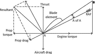
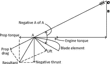
Reverse (or negative) thrust is achieved by turning the prop blades about 30 degrees past the fine/flat pitch stop to a negative angle of attack, referred to as braking pitch. In this position, the resultant force is acting in a rearwards direction, the same as when the prop is windmilling. However, during reverse thrust operations, prop torque is acting in the opposite direction to prop rotation opposing the engine torque as

Reverse Thrust Forces

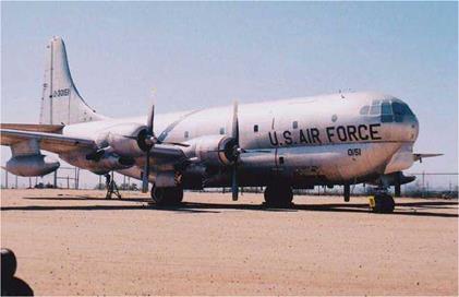
The propellers on this Boeing KC-97G Stratofreighter are all parked in the feathered position; this is unusual for a piston-engine aircraft. The aircraft is stored and displayed at the Pima Air & Space Museum, Tucson, Ar.

shown by Diagram 18, Reverse Thrust Forces. Engine torque is equal and opposite to prop torque acting in the direction from A-B as indicated by the arrowhead. This could cause the prop to attempt to windmill backwards against the power of the engine. The rearward component of the resultant force produces negative thrust to provide a very effective air brake, assisted by the quite considerable prop drag. With the aircraft reducing speed during the landing roll, the vector B-C will reduce. This will cause the negative angle of attack to also reduce, resulting in a decrease in negative thrust. Hence the need to apply reverse thrust early in the landing roll to take advantage of its greatest effect. When operating in the reverse mode, the prop blades are at a negative angle of attack and the prop will be less efficient than at normal forward motion pitch settings. However, full efficiency is not essential due to the brief period reverse is used on the landing roll.

Reverse Thrust Forces

Diagram 18, Reverse Thrust Forces

Windmilling Prop Forces

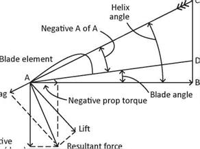
In the event of an engine failure, the prop will continue to turn or windmill for some time after the engine has failed if the prop is not feathered. The force required to turn the prop is provided by the energy in the air flowing through the prop disc due to the forward motion of the aircraft. Referring to Diagram 17, Windmilling Prop Forces, the propeller’s rotational velocity (A-B) is assumed to have decreased but the aircraft’s forward speed is still relatively high (assume the aircraft to be in a glide). The vector (A-C) or relative air flow
(RAF) will strike the prop blade at a negative angle of attack assuming the prop path to be unchanged for the moment. In this condition, the helix angle will be greater than the blade angle and the angle of attack will be negative, the reverse of the normal cruise positions. The negative prop torque acts in the direction of propeller rotation powering the prop to a fast idle speed. With the engine failed, there is no engine torque to oppose prop torque. If the forward speed is increased by lowering the nose, the advance per rev vector (B-C) will be extended, increasing the negative angle of attack and in turn, increase the prop RPM

By reducing the aircraft’s forward speed, the windmilling prop drag can be reduced. Less drag is always an advantage on single-engine aircraft because it reduces the angle of descent allowing more time and a greater distance to be covered in the ensuing forced landing. The reduced windmilling drag on

Подпись: RAFПодпись: Prop dr;Windmilling Prop ForcesNegal

thrust (drag)

Diagram 17, Windmilling Prop Forces

a twin-engine aircraft will lower the minimum control speed (VMC) enhancing engine-out handling. Diagram 17, also shows a reduced forward speed will reduce the advance per rev vector (B-C). The helix angle (AB-AC) will also reduce, thereby reducing the prop blade’s negative angle of attack, which in turn reduces the lift coefficient and the resultant force and hence, it reduces the negative thrust (or drag).

The resultant force acting in the rearward direction produces undesirable negative thrust, known as parasite drag, or more commonly as windmilling drag. The negative prop torque component of the resultant force acts in the plane of rotation causing the prop to windmill. The amount of drag produced depends on the pitch of the prop blades. Additional drag is produced when the prop is set to fine/flat pitch due to it greater negative angle of attack. A coarse pitch setting should be selected for a lower blade angle of attack, less drag and a lower critical speed on a twin-engine aircraft. Coarse pitch will also help to stop the prop from rotating. The windmilling prop drag reduces the overall lift/drag ratio of the aircraft from an average 15:1 to 11:1. The result will be a much steeper glide angle, hence the need to select coarse pitch The drag of a turboprop’s windmilling propeller can be excessively high and dangerous, with the fixed-shaft turbine engine being the worst case due to its inherent design. The drag of a free – turbine engine is only 25% of the fixed-shaft engine.

Propeller Forces & Stress

Prop Forces in Cruise Flight

Подпись: C
Propeller Forces & Stress

With reference to Diagram 16, Forces in Cruise Flight, which is an extension of Diagram 2, Propeller Terminology, shows the propeller’s rotational velocity (A-B) in the prop’s plane of rotation and the aircraft’s forward velocity (B-C). The vector (A-C) represents the relative air flow (marked RAF) or the air inflow velocity into the prop disc (from C to A). This is determined by the prop’s speed ratio (the ratio of the aircraft’s forward speed to the prop RPM). The vector A-C also represents the helical flight path of the blade as it travels in the opposite direction, from A to C.

Diagram 16, Forces in Cruise Flight

Due to the prop blade’s motion along the helical path and its angle of attack, an aerodynamic resultant force is produced, the same as found on the wing in flight. The resultant force can
be divided into the components of lift and drag, but of greater importance, into the components of thrust and prop torque. The blade’s lift coefficient, air density, and inflow velocity and blade area govern the strength of the resultant force. This is shown by the familiar lift formula, Lift (or thrust) = CL%pV2S.

The propeller torque acts in the opposite direction and is equal to the engine torque at constant RPM. Ignoring the effects of a constant speed unit for now, the RPM will remain constant as long as these two forces are equal and opposite. Also, the prop’s thrust is equal and opposite the aircraft’s total drag. The forward component of the resultant force (the dotted line under the word ‘lift’) is equal and opposite the rearward component of prop drag (shown by the dotted line above the words ‘prop drag’). These two forces cancel out leaving prop thrust to equal prop drag.

The vectors of relative air flow, thrust and torque, etc, have been drawn as emanating from the trailing edge of the prop blade element. In practice, this is not true because the forces all act from the blade’s centre of pressure. This diagram and the following two have been drawn this way for the purpose of clarity Note here, how the blade element theory differs from the axial momentum theory covered in the section on Propwash-Thrust.

Synchronizing

One source of noise audible to the occupants of twin-engine aircraft occurs when the propellers are not synchronized. The noise can be heard as a throbbing sound when the props are ‘out of synch’ caused by a vibration due to the difference in RPM between each engine. When the props are correctly synchronized the noise becomes a steady hum. The vibratory frequency is only a discomfort to the occupants and does not in any way affect the structural integrity of the airframe.

The propellers can be synchronized in one of four different methods. The first two manual methods apply to light twin – engine aircraft, and the following two methods are applicable to larger more sophisticated aircraft. On a twin-engine aircraft with fixed-pitch props (not many around these days) the required RPM/power is set first with the throttles and then one throttle is slowly adjusted either way until the throbbing noise becomes a steady hum. With constant-speed props,

Synchronizing

The North American B-25J Mitchell bomber has rounded
prop tips, typical of many aircraft until the 1960s
when square tips became common. Pima Air & Space
Museum, Tucson, Ar, is home to this aircraft.

the required manifold pressure is selected with the throttles followed by selecting the chosen RPM with the prop pitch levers in the usual manner. One prop lever is then adjusted either way to synchronize the props to a steady hum. Depending on the make of engine, some props are more easily synchronized by retarding the prop pitch lever, and on other engines the lever should be advanced. The throbbing beat will slow down and merge into a steady hum when the control is moved in the correct direction, while a quickening of the beat indicates the control is being moved the wrong way, so readjust accordingly.

Turboprop aircraft employ the use of a prop synchronizer. This is an electrical system comprising a generator mounted on each engine, with one engine (usually the right-hand engine) being the master unit. Signals from the left-hand engine’s generator are adjusted electrically to match those of the master unit, ensuring all propellers rotate at the same RPM

The fourth method uses a prop synchrophaser, developed by Hamilton Standard in 1978. The synchrophaser controls the engine RPM exactly by ensuring the prop blades on each engine pass through the same angular location at the same time. The prop’s RPM is fine-tuned electrically by the phase signals from each engine’s generator. When the props are turning with a phase difference of plus or minus one degree, a noise reduction of to 6.5 decibels (6.5 dB) is possible, while a phase difference of plus or minus five degrees produces a 4.5 dB reduction. Commuter and business aircraft usually employ the ± 5° phase due to the lower installation costs. A control is provided for the pilot to fine tune the system by altering the phase angle slightly in order to obtain the preferred sound level. The system can also be turned on or off as required, but must always be turned off for take-off and landing in case of engine failure. Decreasing engine RPM on the failed engine would cause the other engine to follow suit, if engaged.

How Noisy are They?

So far, only a brief reference has been made to the amount of noise produced by the props. So, how noisy are they? Answer – quite a lot, but to be more precise… the noise will be in the region of 76-80 dB during take-off for a high performance single-engine aircraft, decreasing to around 70 dB or even lower for an aircraft with a fixed-pitch propeller. Fixed-pitch props are generally quieter due to the prop’s relatively smaller diameter and lower RPM, which are the two main factors that influence the tip speed and prop noise. It follows, a fixed-pitch prop with a relatively short diameter does not attain full RPM during take-off and because its tip speed is typically around 600 feet per second at 2500 RPM, it will be relatively quiet. Conversely, a high-performance single with a constant-speed prop will attain maximum RPM (2700-2900) during take-off

Synchronizing

A Lockheed YO-3 Quiet Star observation aircraft, with a three – blade, wide chord prop. This is one of the quietest planes built due to the very quiet propeller and other features. It is housed in the Pima Air & Space Museum, Tucson, Ar.

and climb out, and will generate considerably more noise due to the greater RPM and higher tip speed. For any given aircraft, a three-blade prop will usually be of shorter radius than a two – blade propeller and three-blades are preferable because they generate more acceptable sound frequencies than two-blade props

The American FAA 36 noise regulations (1988) places a limit of 80 dB maximum for the certification of new aircraft types, but some older aircraft can easily exceed this figure. It is up to the individual pilot to operate his/her aircraft as quietly as possible to avoid undue noise to airport neighbors. A noise abatement departure can be achieved by reducing the RPM as soon as is safely convenient after take-off and then climbing at the maximum rate of climb to gain as much altitude as possible before reverting to the cruise/climb procedure. The intensity of the plane’s noise will decrease inversely with the square of the distance from the plane, altitude and distance are both excellent buffers of noise. However, what noise is sweeter than that of an aircraft taking-off and flying overhead? It sure beats ‘heavy metal’ rock music!

Tips, Blade Shape & Materials

Wooden propellers due to their inherent thickness required for structural strength, are more suitable for low speed aircraft with lower tip speeds operating up to 660 FPS (200 m/sec) maximum. At higher speeds, the thicker sections create more drag and compressibility may become a factor. Metal props have thinner blade sections and they can operate to higher tip speeds: 880 FPS (268 m/sec) is an average

Tips, Blade Shape & Materials

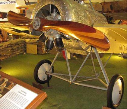
A Fokker E-MI Eindecker of WW I era with a carved, laminated and scimitar shaped propeller. This aircraft is located in the Air & Space Museum, San Diego, Calif.

maximum. New types of propellers now being produced have supercritical airfoil sections that can operate with high critical Mach numbers. They are less affected by the drag rise and noise associated with high tip speed due to their favourable thickness/chord ratios. Composite materials such as Kevlar, graphite, carbon or glass fibre are all used in the manufacturing of propellers. Composite materials are considerably stronger and lighter than wood or metal props, which helps to reduce the load on the prop hub. They also have a higher aspect ratio and operate to higher tip speeds than either wood or metal props, while still maintaining excellent efficiency.

Although wood propellers are usually associated with low powered aircraft, the German prop manufacturer MT – Propellers has been making props ranging from fixed-pitch props for light, home-built aircraft and right up to include constant-speed props with electric or hydraulic constant – speed units for powerful turboprops of up to 1500 shaft horsepower The propellers, from two to six-blades per prop are made with a wood base covered with fiberglass. Their advantage is their lightweight, and also the fiberglass can be replaced if damaged.

Another factor that contributes to tip speed noise is the shape of the prop blade and its tip. For some reason, square tips tend to run quieter than round tips and from the early 1960s the square tip has become the one mostly used, with a few exceptions. The Piper Cheyenne III, introduced in 1979, was the first production aircraft to sport ‘Q-tip’ propellers as standard equipment. ‘Q-tip’ propellers have a form of end plate where the last two inches (5 cm) of the prop tip is bent upwards at a 90° angle, similar to winglets found on modern jet transport aircraft. The ‘Q-tips’ are there to reduce back-side pressure from leaking around the tips and to enable high blade span loadings to be achieved at a lower RPM than normal, thus reducing prop noise and improving efficiency. The advantages of ‘Q-tips’ is debatable and can vary between different installations. One advantage is the reduced prop diameter allows greater tip clearance from the fuselage on twin-engine aircraft, which will reduce cabin noise. The ‘Q-tip’ may alter the prop tip vortex reducing the amount of gravel picked up during take-off and hence reducing prop blade leading edge damage. Also, at low air speed and high power such as on the climb, is where they work the best.

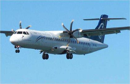
Another modification for propellers was the introduction of the use of sweptback tips. They work in the same manner as swept back wings on a jet aircraft by increasing the blade’s critical Mach number, allowing the prop to run at speeds closer to Mach 1.0, with reduced noise. Curved or scimitar shaped blades are an alternative to swept-back tips having a similar effect. The scimitar shape is ideal for Propfans, which will be covered later. They are also becoming more popular on new generation turboprop aircraft such as the Aerospatiale ATR commuter aircraft. The scimitar shape obviously provides better aerodynamic performance on today’s modern aircraft, but the shape is not a new idea. Several early aircraft from the World War one era used scimitar shaped props. Was it for aerodynamic or aesthetic reasons the early prop designers chose the scimitar shape? After the WW I era, the style faded away and prop blades were made straight (usually with round tips) and now the scimitar shape is becoming more common again. During the 1960s, the slender or elliptical tip became more popular, possibly because elliptical tips have greater efficiency than square or rounded tips. The tip shape also has an effect on the prop’s vibration characteristics – another problem for the prop designer to contend with. Hartzell and McCauley produce scimitar shaped blades for light aircraft.

Tips, Blade Shape & Materials

The Aerospatiale ATR-72 turbo prop aircraft have modern six-blade scimitar shaped props.

Tip Speed

The prop tip speed can be found, in feet per second, given the RPM and prop diameter from the following formula:

Prop tip speed = 2nRN

Where: 2 = a constant n = 3.14…

R = prop radius in feet N = prop revs per second

Given the following figures the prop RPM in FPS can be found:

Prop radius = 74 inch/2 = 37 inch = 3.08 feet Revs per second = 2700/60 = 45 revs per second

Prop tip speed = 2nRN

= 2 x 3.14. x 3.08 x 45 = 870 FPS

An alternative and simpler formula to the one above is as follows:

Подпись: Prop tip speed in FPSRPM x diameter

229.3

2700 x 74 inches

229 3 = 870 FPS

In the example above, the propeller rotating at 870 FPS on take-off at full RPM would be operating very close to Mach 0.8, where efficiency begins to deteriorate and the prop’s noise level is about to exceed the maximum allowable limits. An aircraft designer may consider a propeller reduction gear to reduce the tip speed to a value of 0.7 to 0.8 of the engine speed. One example of using prop reduction gear was demonstrated on the Australian CAC Wirraway, a licensed built version of the North American Harvard. The Wirraway’s geared engine driving a three-blade prop at a slower RPM was much quieter than the Harvard’s distinctive growl on take-off.

So far, we have only considered the effects of the rotational velocity on the prop tip speed (vector A-B on Diagram 2, Propeller Terminology). To this vector we must add the vector representing the props advance per rev (B-C). We now have the third vector in the triangle (vector A-C) corresponding to the propeller’s helical flight path. Because the vector A-C is of greater length than vector A-B, it follows the prop tip speed will be higher when the aircraft’s forward speed is increased from zero up to cruising speed. Using the above formula again, and the 74 inch propeller turning this time at 2400 RPM, we find the prop tip speed to be approximately 775 FPS (236 m/ sec) when the aircraft is stationary Increasing the plane’s forward speed up to 142 knots, the prop tip speed increases to around 810 FPS (247 m/sec). The noise level would be fairly high but acceptable at this speed.

Generally at tips speed of around 600 FPS (183 m/sec) the prop will be relatively quiet but, the noise level will start to increase around 700 FPS (213 m/sec). At 880 FPS (268 m/sec) the prop could be unacceptably noisy, as mentioned above. When the prop tip speed approaches the speed of sound, compressibility problems and tip vortex losses increase, which in turn reduces thrust, efficiency and increases prop torque and noise. Mach 0.8 or 880 FPS (268 m/sec) is about the maximum tip speed a normal prop can safely operate to,

but there are a few exceptions with some props designed to run at transonic tip speeds (Mach 0.8 to Mach 1.20).

High-speed Aerodynamics

Moving into the area of high-speed aerodynamics as applied to propellers, the definitions of the speed of sound and its associated critical Mach number and the effects of compressibility will now be considered.

The speed of sound varies with the ambient temperature and air density. Because air density is closely related to temperature, it can be ignore in the calculations. At sea – level where the International Standard Atmosphere (ISA) temperature is assumed to be +15 °C (288 K) the speed of sound as 661 knots and varies in proportion to the square root of the Absolute temperature. The speed reduces to 575 knots in the Stratosphere where the temperature is assumed to be at minus 56.5 °C (or 216.65 K). The speed of sound is also known as acoustic velocity, Mach number 1, or more simply as Mach 1, after Dr. Ernst Mach (1838-1916) the Austrian philosopher and physicist. Mach number is the ratio of aircraft speed to the speed of sound, or in this case the propeller tip speed to the speed of sound.

At subsonic speeds, below Mach 0.8, air acts as if it is incompressible and this assumption is fine until speeds greater than 300 knots and altitudes of 10,000 feet are considered and where the effects of compressibility and air density can no longer be ignored. The aircraft wings, or prop blades, cause compressibility as they move through the air sending pressure waves ahead of it, which travel at the speed of sound and cause the approaching air flow to separate and travel over and under the wings or prop blade surfaces. As the prop tips approach the speed of sound, the pressure waves have less time to move ahead of the blade and they eventually become stationary on the blade’s surface. This causes an increase in compressibility resulting in a serious loss in propeller efficiency, which in turn, reduces thrust and causes a rapid rise in blade drag, prop torque and especially noise.

Altitudes above 25,000 to 30,000 feet are the domain of jet propelled aircraft and not many propeller-powered aircraft are found there, due to the reduction in air density, air temperature and pressure. Propellers are unable to cope with the reduced air density at these high altitudes and at 40,000 feet the thrust produced by the propeller is reduced to around 25% of the sea-level value. How does the reduced air density at high altitudes affect the thrust produced by the prop? An inspection of the familiar lift formula below shows it can be applied to the propeller thrust:

Thrust (or lift) = CL%pV2S

Where CL = lift coefficient % = a constant p = air density V = prop RPM in FPS S = prop blade area

If the blades area (S) is assumed to be constant and the air density (p) is reduced at altitude, the lift coefficient (CL) and prop speed (V) are the two variables. The lift coefficient can be increased by increasing the blade pitch angle but this increase is offset by the prop speed decreasing. [Remember that coarse pitch produces lower RPM]. Therefore, with the lift coefficient, RPM2 and blade area all doing nothing to increase prop thrust, it follows the remaining factor of air density is the only remaining variable and because air density decreases with altitude, prop thrust must also decrease.

It is common knowledge air temperature decreases along with air density as altitude increases. Not only is the prop’s thrust decreasing with altitude but the speed of sound is also decreasing This has a detrimental affect on propeller performance The prop blades are working closer to the speed of sound at altitude than they do at sea-level due to the difference in air temperature. This can be shown by calculating the tip Mach number (Mt) for a given aircraft’s prop at sea – level (s/l) and for example 20,000 feet from the formula:

Tip Mach number = V. tip/speed of sound

Where: Prop tip speed (V. tip = 870 FPS S/l speed of sound = 1100 FPS 20,000 feet speed of sound = 1040 FPS

Mt at s/l (15 °C) = 870/1100 = Mach 0.79 Mt at 20,000 feet (-25 °c) = 870/1040 = Mach 0.83

In the above figures, the prop has a higher tip Mach number at altitude and it is therefore operating closer to the speed of sound with efficiency deteriorating. Closely associated to the speed of sound is the term critical Mach number. This is the speed at which the airflow over a body, or prop blade, reaches Mach 1.0, due to the blade’s curved upper surface, while the prop blade itself is actually moving at a speed below Mach 1.0 . It is the thickness/chord ratio that determines the critical Mach number of an airfoil, which increases with thinner prop
blades with a high aspect ratio and is therefore more important operationally than the speed of sound.

Incidentally, when the prop tip approaches the speed of sound, a condition occurs known as ‘cavitation’, caused by a near vacuum on the suction face of each prop blade near the tips, which again reduces efficiency.
– Prop Tip Speed & Noise

Tip Speed & Noise

Have you ever had the privilege to hear the beautiful sound of a Merlin-powered aircraft take-off or fly overhead? Or heard the rasping sound of a rowdy radial engine, or the thundering roar of a jet aircraft taking-off? All this noise is sweet music to a pilot’s ears, but not so for local residents living near an airport. To the locals, it is a very disturbing nuisance. To this end, aircraft and propeller manufacturers all attempt to reduce aircraft noise as much as possible. In fact, certification requirements for all new aircraft designs stipulate the maximum allowable noise limits.

The Cause of Noise

Noise is generated by the engine, exhaust system, propeller propwash and the prop itself. The prop noise is dependant on the blade loading, number of blades, prop diameter, and the location of the prop on the aircraft. However, the main cause of noise is the propeller tip speed

Consider a two-blade prop installation: the prop produces an inherent vibration once per revolution that will vibrate through the airframe to be heard as noise. The greater the number of blades, the less is the vibration and noise produced. Single-engine aircraft have their prop wake striking the cockpit windshield adding to the vibration and noise as opposed to multi-engine aircraft with their props further away from the cabin

Tractor props mounted on the aircraft nose or in front of the wings are generally quieter than pusher props, which operate in the disturbed air flow passing over the aircraft creating resonance or noise in the cabin. However, the greatest amount of noise is heard the prop’s plane of rotation. On a twin, or multi-engine aircraft, any occupants seated in line with the props will suffer the most noise. Moving the engine/ prop further out board on the wing will help to reduce the noise heard in the cabin, but this will also increase engine-out asymmetric forces, as mentioned above.

‘Shrouded props’, or ‘Propulsors’ are claimed to be considerably quieter than conventional props due to the shroud around the propeller and also the lower tip speed (they are usually props of smaller diameter). But, the disadvantage here is, the prop noise can be directed more fore and aft by the shroud. Therefore the amount of noise heard to a certain extent is dependant on one’s external position relative to the aircraft, or their position inside the aircraft

Contra-rotating Propellers

Two co-axial mounted propellers driven by the same engine, but rotating in opposite directions are known as contra-props. Using two propellers mounted on the same co-axial shaft with a given propeller diameter, will absorb a greater amount of horsepower than a single prop unit. The rear-mounted propeller in the pair straightens out the helical propwash from the front propeller, which reduces the total propeller torque to zero and hence, take-off yaw and in-flight yaw caused by power changes. This is the important factor on high-powered aircraft

Contra-rotating Propellers

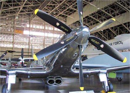
The Fisher P-75A Eagle, the last of 14 built, has a contra-prop powered by an Allison V4320 engine of 2600 BHP mounted amid-ship. It must rank as one of the earliest contra-prop aircraft to be built, (in 1943). This aircraft is displayed in the Research Section of the National Museum of the USAF, Dayton, Ohio.

Additionally, the wing’s structural loading on multi-engine aircraft will be greatly reduced due to the absence of prop torque. On the down side, the disadvantages are the increased weight and complexity of the co-axial prop shafts. Contra – props have their own distinctive noise due to the rear prop interrupting and reacting on the helical propwash vortex formed by the front prop.

Contra-rotating Propellers

Contra-props mounted on the Fairey Gannett AEW3 in
the Yorkshire Air Museum, Elvington, England.

Counter-rotating Propellers

On twin-engine aircraft, the props of each engine may rotate in opposite directions with the top blade rotating in towards the fuselage. These are known as counter-rotating propellers.

The main advantage of counter-rotating propellers is during take-off and climb-out after an engine failure. On a conventional twin-engine aircraft with both propellers turning clock-wise, asymmetric thrust causes the greatest yaw when the left-hand engine is shutdown. This is due to thrust generated on the

Counter-rotating Propellers

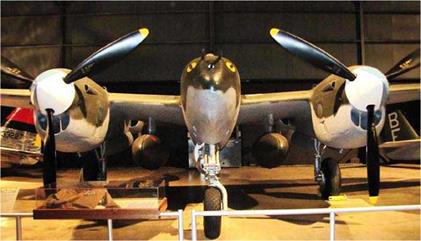
A front-end view of a Lockheed P-38 Lightning showing its counter-rotating propellers. This aircraft is located in the National Museum of the USAF, Dayton, Ohio.

down-going side of the propeller disc, remember the P-factor or asymmetric disc loading! On right-handed propellers the center of thrust to displaced to the right of the propeller axis. On the right-hand engine it is further away from aircraft’s normal axis, and the centre of thrust on the left-hand engine will be closer to the aircraft’s normal axis. If the left-hand engine fails, the right-hand engine will produce the greatest yawing moment due to the centre of thrust being displaced further outboard. The drag of the windmilling left-hand prop will contribute to the yawing force. In this instance, the left – hand engine is said to be the critical engine, due to the greater yaw force caused by the thrust from the right-hand engine.

On a twin-engine aircraft with counter-rotating props, both props will have the centre of thrust an equal distance from the aircraft’s normal axis. Therefore, the failure of either engine will produce an equal yaw force. The critical engine is

Counter-rotating Propellers

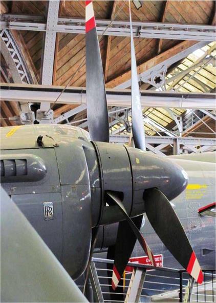
Four sets of contra-props power the Avro Shackleton
AEW.2 maritime patrol aircraft. This aircraft resides in the
Museum of Science & Industry, Manchester, England.

eliminated and single-engine performance will be the same with either engine failed.

Airplanes with propellers rotating anti-clockwise, or ‘left­handed’ propellers, will have their right-hand engine as their critical engine. The ‘critical’ engine is so named due to the control problems being more critical when the critical engine is shut down. The Fokker F.27 Friendship is one aircraft that comes to mind with a right-hand (Number 2) critical engine, due to the left-hand rotation of its propellers powered by their Rolls Royce Dart fixed-shaft turboprop engines.

The location of the wing-mounted engines on twin-engine aircraft is also important. Placing the engines too near to the fuselage will not only increase noise in the passenger cabin, it can also affect the amount of thrust produced by the propeller. The closeness of the fuselage affects the free air flow between the prop and fuselage. This has an affect on the prop by slightly reducing the prop thrust of the prop on one side of the aircraft, while the prop on the other side remains unaffected. Although this imbalance of thrust is not as great as the ‘P’ factor or asymmetric disc loading, it is still present to a certain degree .