Category Propellor Aerodynamics

Fixed-pitch Propellers

It has been assumed up to now, the propeller to be of the fixed-pitch type, as found on low performance aircraft. The advantages of the fixed-pitch prop are its simplicity of operation for low time pilots, it is the cheapest type to install on an aircraft and it is relatively maintenance free due to the absence of a constant-speed unit (CSU). Its disadvantage is it gives its maximum efficiency at only one air speed, known as the ‘design air speed’. At any other speed, above or below the design air speed, the prop efficiency will be reduced. However, in general, a prop will normally be chosen from a family of props to suit the aircraft’s design air speed. In order to produce the maximum amount of thrust for the least amount of drag or torque, each blade element is set to a different angle to ensure the optimum angle of attack is maintained at the prop’s speed ratio to produce its maximum efficiency. This is the reason why the prop blade is twisted. If the blades were not twisted, the blade root would be operating at a negative angle of attack

while the prop tip would be stalled when operating at the design speed ratio.

At the design air speed, maximum efficiency also depends on the geometric pitch. A prop with a relatively short geometric pitch will give the aircraft a better rate of climb over a prop with a longer geometric pitch. The short pitch prop is more suitable for a training aircraft or aerobatic aircraft which spend a relatively greater proportion of their flying time at lower air speeds, doing training manoeuvre and climbing to altitude. Conversely, a longer pitch prop produces a slightly higher cruising speed, favouring an aircraft used for cross­country flying. Longer pitch props may not attain full RPM at the start of the take-off roll, due to the blade’s high angle of attack causing too much blade drag. However, if the pitch is too fine, the RPM will reach a maximum with the aircraft stationary or early in the take-off run. On reaching cruising speed the engine RPM would exceed its limit, calling for a reduction in engine power. The American FAA certification rules require the propeller pitch to be such that it prevents the engine from over-speeding at maximum RPM, while climbing at the ‘best rate of climb speed’. Likewise, the engine’s RPM is not allowed to be exceeded by more than 10% in a dive at the never exceed speed (VNE) with the throttle closed. The same rules apply to constant-speed propellers.

It is now obvious, selecting a propeller with the desired pitch is very important. Propeller manufacturers list a selection (or family) of props designed for certain engines to aid the aircraft designer in his/her choice of propellers. There can be found on the prop hub a set of numbers such as 72" x 57". The first number refers to the diameter of the prop in inches, while the second number refers to the geometric pitch in inches at the ‘standard radius’.

When flying a plane with a fixed pitch prop in conditions of turbulence, you may notice some rapid variation in RPM. This could be very disconcerting, inducing you to suspect

Fixed-pitch Propellers

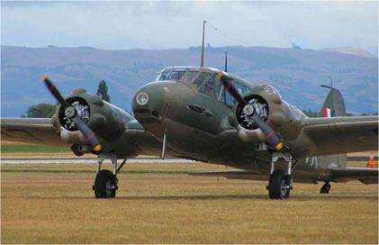
This beautifully restored Avro Anson Mark 1, of WW II vintage has fixed-pitch, two-blade, wooden propellers powered by two Armstrong Cheetah IX seven-cylinder radial engines of 350 BHP each.

engine trouble. The cause of the engine RPM variations can be attributed to the propeller loading and un-loading. As the aircraft attitude is constantly changing in the turbulence, the air flow through the prop disc will meet the blades at varying angles of attack causing variations in prop loading and hence a change in thrust and RPM. The throttle should be set to maintain the required RPM for turbulence penetration air speed (Vb) and be left there. The RPM will fluctuate around the desired setting, so do not chase it with the throttle; set it and forget it!

Advance/Diameter Ratio

The aircraft designer has to choose the propeller with the most suitable pitch and diameter for the aircraft and its intended mission and design air speed. When confronted with a family of props which have their blade angles increasing in some systematic order, one useful parameter to refer to is the advance/diameter ratio. The advance/diameter ratio can be used to define the characteristics of a prop using a non­dimensional form. The advance/diameter ratio (J) is the ratio of the aircraft’s velocity (TAS) to the product of propeller RPM and diameter

V

The advance/diameter ratio, J = ^

Where, V = true air speed N = RPM

D = propeller diameter

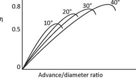
Diagram 6, Advance/diameter Ratio shows the curve for the advance/diameter ratio plotted against efficiency for a family of props with their pitch increasing. The numbers above the curves shows the blade angles for each propeller. The efficiency increases with an increase in the ratio up to a certain limit. At too high a ratio, the angle of attack of the blades exceeds the stalling angle at low forward speeds reducing the thrust available for take-off. Reducing the propeller’s diameter also reduces the efficiency by over working the prop blades, but more of this later. A fixed-pitch propeller’s efficiency curve moves to the left with a decrease in RPM and TAS and to the right with an increase of RPM and TAS power. Diagram 6, also shows the curves for a fine/flat pitch prop and a coarse pitch prop, 10 and 40 degrees respectively. Most single-engine light aircraft have a prop between these two extremes A constant speed propeller has an infinite number of curves between the fine and coarse pitch limit stops; the pilot selects the optimum setting for climb or cruise.

Slip function and effective pitch are alternate names for the advance/diameter ratio

Advance/Diameter Ratio

Diagram 6, Advance/diameter Ratio

Brief Review

Before moving onto the next section, we will briefly review the

differences between the slip, advance per rev, experimental

pitch and the geometric pitch

• Slip is a variable and is the difference between the advance per rev and the geometric pitch.

• The advance per rev (effective pitch) is less than the geometric pitch and experimental pitch under normal operating conditions. The advance per rev is also a variable.

• When the advance per rev is equal to the experimental pitch, the angle of attack is slightly negative with zero slip and thrust.

• When the advance per rev is equal to the geometric pitch, the blade’s angle of attack is zero with a small amount of slip and thrust still present.

• The experimental pitch is a constant.

• The geometric pitch, which is also a constant, is usually less

than the experimental pitch

• On diagrams 2, 3 and 4, note the location of the relative air

flow (RAF) vector.

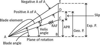
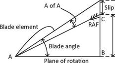
In conclusion and referring back to Diagram 2, Propeller Terminology, the following points should now be obvious. All sections of the propeller blade have an advance per rev equal to the aircraft’s forward speed. The vector A-B, represents the rotational velocity of a given blade element. The vector A-C represents the resultant direction of motion of the chosen blade element. Because the length of the vector A-B varies with each individual blade element, it follows each blade element travels on a different helical flight path with its rotational velocity increasing from the hub to the tip.

The vector A-B increases with increasing RPM and therefore the effective pitch (advance per rev) will also increase vector B-C. Conversely, the effective pitch will also increase if the aircraft’s forward speed is increased. Therefore, the effective pitch increases along with the helix angle, which in turn increases the prop efficiency and thrust up to a certain point. As the advance per rev increases, the blade’s angle of attack decreases and reduces the thrust and efficiency. This is where a variable-pitch or constant speed propeller becomes a necessity in order to increase the blade angle and geometric pitch to maintain the required angle of attack, for the increasing combination of prop RPM and the aircraft’s forward speed, known as the speed ratio.

Slip

The ‘slip’ of the propeller can be defined as the ‘difference between the advance per rev and the geometric pitch’.

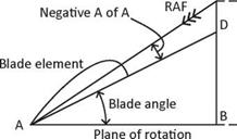
When the advance per rev equals the experimental pitch, the angle of attack is slightly negative and produces zero thrust. However, in normal operating conditions, the angle of attack is around positive three degrees and the advance per rev is considerably less than the geometric pitch. Diagram 4, Geometric Pitch, shows the advance per rev (B-C) plus the slip (C-D) is equal to the geometric pitch (B-D). For the propeller to provide maximum thrust and efficiency, and because air is not a solid medium, slip must be present. Maximum efficiency is only obtained when the slip, expressed as a percentage is around 30% of the length of the geometric pitch. In other words, slip is the difference between the actual distance the prop travels forward in one revolution (B-C or effective pitch) and the distance the prop would theoretically travel in on revolution if its advance per rev were equal to the geometric pitch (B-D). Slip is a percentage of distance.

Given the prop RPM, prop pitch in inches and true air speed in knots, the slip can be found using the following formula:

Подпись: Slip =RPM x pitch x 60

6080 x 12

Given: RPM = 2400

Pitch = 69 inches TAS = 100 knots

2400 x 69 x 60

Подпись: Then slip =6080 x 12

= 136.18 inches = 26.57%

It must be emphasized that slip is related to the geometric pitch and the advance per rev. As stated above, zero thrust occurs at a negative angle of attack (experimental pitch) and thrust increases as the angle of attack increases through the geometric pitch up to some positive angle of attack. Diagram 4, Geometric Pitch, shows a small amount of slip (C-D) is present when the prop blades are operating at zero angle of attack (geometric pitch). To produce thrust, slip must be present with the maximum prop efficiency occurring at around 30% slip, or 30% of the geometric pitch. It must be remembered slip is related to geometric pitch, which is the distance the prop travels during each revolution.

Geometric Pitch

The geometric pitch is defined as ‘the distance the propeller advances forward in one revolution when the angle of attack of the blades is at zero degrees’.

Geometric

pitch


Diagram 4, Geometric Pitch


Geometric Pitch

Diagram 4, Geometric Pitch explains this clearly. When the prop is advancing with zero degrees angle of attack, the advance per rev is equal to the geometric pitch. This distance is a definite length measured in inches for a given propeller (as mentioned above) which depends on the geometry of the blades, hence the name geometric pitch. To maintain a constant pitch, the angle of each blade section must increase from the blade tip to the blade root in order to obey the law, geometric pitch = 2nR tan в. This was explained earlier in the section on Blade Angle. The equation should hold true for the whole length of the prop blade, but if it does not, the geometric pitch is stated for one section of the blade only at the ‘standard radius; this point is located at the 75% station along the length of the prop blade from the hub. From the above formula, we can find the geometric pitch of a propeller in inches as follows:

Geometric pitch = 2nR tan 0

Given: Pitch = 22° (tan 0.4040…)

Propeller radius = 26 inches n = 3.14…

Therefore pitch = 2 x 3.14. x 26 x 0.4040.

= 66 inches

An inspection of Diagram 4, Geometric Pitch, will reveal a small amount of slip is still present. A small amount of thrust is still generated by the prop at zero degrees angle of attack, which can be attributed to the curved shape of the propeller’s back. Generally, the geometric pitch is less than the experimental pitch; however, this may not always be true.

Geometric Pitch

Diagram 5, Lift Coefficient V. Angle of Attack

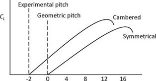
To clarify the points made here regarding the experimental and geometric pitch, the prop blades can be related to the aircraft’s wings and tailplane The vertical tail is a symmetrical airfoil and so both sides are of equal curvature. However, on most aircraft (aerobatic aircraft can be an exception) the main wing is cambered; the upper surface has greater curvature than the lower surface. The propeller blades are shaped similarly. An inspection of Diagram 5, Lift Coefficient V. Angle of Attack, shows the symmetrical airfoil section ceases to produce lift at zero degrees angle of attack. However, of greater interest here, at zero degrees angle of attack, the cambered airfoil is still producing lift, or thrust in the case of the propeller as indicated by a positive lift coefficient. This point corresponds to the prop’s geometric pitch. A further reduction in angle of
attack to minus two or three degrees will eventually produce zero lift coefficient, known as the angle of zero lift for the wing or the angle of zero thrust for the propeller. This corresponds to the prop’s experimental pitch.

Experimental Pitch

The experimental pitch can be defined as the ‘prop’s advance per revolution when producing zero net thrust’.

An inspection of Diagram 3, Experimental Pitch, shows as the advance per rev (APR) increases from B to E, the angle of attack will reduce to a negative angle (AD-AE) of around minus two degrees and the propeller will cease to produce thrust. In

this condition the relative airflow acts along the line from E to A, and corresponds to the wing’s ‘zero lift line’, to become the prop’s zero thrust line. This is the important aerodynamic feature of the experimental pitch. From the designer’s point of view, it is considered as being the ‘ideal pitch’. Because it has a definite value and length, depending on the prop’s characteristics, it can be used for experimental measurements, hence the name

Подпись: EПодпись: *Подпись:Experimental PitchExperimental

pitch

A fixed-pitch propeller has only one experimental pitch, while a constant-speed prop’s pitch is variable over the available operating range of the blade angles between the fine and coarse pitch stops. The experimental pitch may also be known as the ‘zero thrust pitch’ or the ‘exponential mean pitch’

The Working Fluid

The volume of air in which the propeller works is the working fluid, and is described as an inviscid fluid flow. The term inviscid describes the air flow and assumes it to be one without viscosity, or devoid of any internal friction or drag force. The airflow approaching the prop is termed the relative air flow (RAF) and shown by three arrow heads on the diagrams; it is also known as the inflow velocity. The air flow behind the prop is termed the propwash or outflow.
The Working Fluid

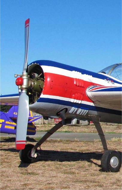
A wide chord prop with squared off tips adorns
this Yak-55M aerobatic aircraft.


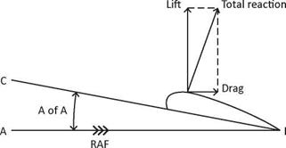
All pilots should be familiar with the diagram below, Diagram 1, Airfoil Terminology, from their previous study of classical aerodynamics. The diagram depicts the terminology used in defining the wing’s airfoil section, chord, relative airflow, angle of attack, lift, drag and total reaction.

The Working Fluid

Diagram 1, Airfoil Terminology

Briefly, the line A-B represents the path the airfoil is moving along. The relative airflow is therefore moving along the same path, but in the opposite direction and depicted by the three arrow heads. The line C-B represents the extended chord line and the direction the airfoil is pointing. The angle between A-B and C-B, that is, between the relative airflow and the chord line, is the angle of attack. Due to the angle of attack, the air mass flowing over the airfoil will produce an aerodynamic reaction known as the total reaction (TR), which can be divided into the forces of lift and drag The propeller is a rotating wing and shares the same terminology as the aircraft’s wing. Because the prop is rotating around its axis combined with the forward motion of the aircraft, it requires additional vectors and terminology to fully describe it, as follows:

• The chord line is taken to be a tangent to the lower surface of the prop blade.

• The blade element is a theoretically thin cross section of the prop blade (it is the counterpart of the wing’s airfoil section) and is perpendicular to the blade’s major axis. The blade profile is the shape of this cross section of the blade.

• Confusing as it may sound, the propeller’s back is the curved, upper surface and this part of the prop is viewed from in front of the aircraft.

• The prop blade’s relatively flat surface corresponds to the wing’s under surface and is known as the prop blade’s face, thrust face or pressure face due to this side of the propeller producing air pressure above ambient, but more of this later in ‘Propwash Thrust’. The face is usually painted a matt black to reduce reflection making it easier for the pilot to see through the prop disc in flight.

• The shank is located at the blade root and being circular; it is not an aerodynamic shape and therefore plays no part in producing thrust, although it does produce some drag. Not all propellers have shanks.

• The propeller’s boss is the thick central non-aerodynamic part of a wooden fixed-pitch prop.

• The hub is in the same central position as the boss but is a separate unit to which the blades and constant-speed unit are attached

• The spinner is the streamline fairing covering the hub area. On some aircraft it is used for aesthetic reasons or it may also be an essential item on other aircraft to smooth the airflow into the engine air intakes, and reduce drag.

• The prop blade’s leading and trailing edges, plus the tips and roots, all share the same terminology as applied to an aircraft wing.

The blade cuff is located at the blade root to enhance air flow into the engine intakes and for greater propeller solidity.

The Working Fluid

Diagram 2, Propeller Terminology

Comparing Diagram 2, Propeller Terminology with Diagram 1, it is shown the blade element, chord line, relative airflow and angle of attack are all shown similarly, albeit reversed [Classical aerodynamic diagrams by convention are shown as moving from right to left, and the reverse direction for propeller aerodynamic diagrams]. Diagram 2, also shows the relationship of the helix angle AB-AC, the blade angle AB – AD, the angle of attack (AC-AD), all measured in degrees. The advance per rev (B-C), the geometric pitch (B-D), the slip (C-D) and the experimental pitch (B-E) are all measured in inches; vector B-E represents the prop’s axial (or forward) component. Using a breakdown of Diagram 2, each factor can now be examined in more detail, keeping the following points in mind All that follows will also apply to a constant-speed propeller; however, it will be assumed for now a given blade section on a fixed-pitch propeller is being considered where the geometric pitch and experimental pitch both remain constant and the advance per rev and slip are variables Also, vector A-B represents the tangential component or plane of prop rotation

What is the definition of pitch? And what is the difference between the experimental pitch, the geometric pitch and the advance per rev? The difference will be revealed as each term is considered in turn.

The definition of the term ‘pitch’ and its analogy with the common screw must be defined. When a screw is screwed into a solid medium such as wood, it will advance a given distance in each turn equal to its pitch; in other words, its advance per revolution is a fixed quantity equal to its pitch. The geometric pitch of the screw is the distance between each adjacent thread

When an aircraft is gliding with the engine/prop stopped, the propeller’s advance per rev is infinite, as opposed to a stationary aircraft with the engine running and the prop’s advance per rev is zero The advance per rev of the propeller is a variable quantity depending on the aircraft’s speed, and propeller RPM, or lack of either, between these two extremes.

Some text books state the analogy with the wood screw is useless, because the screws advance per rev is a fixed quantity, while the props advance per rev is a variable quantity between zero and infinity. That is true, but there has to be a condition of propeller operation somewhere between these two extremes that satisfies the definition of geometric pitch. And there is! When the aircraft reaches a given forward speed, the propeller blade’s angle of attack will become zero and the advance per rev will equal the geometric pitch, which is exactly what happens with a wood screw

In conclusion, two things have been proven, one, the screw analogy is a true and useful example to introduce the definition of pitch, and two, under certain operating conditions of aircraft forward speed and prop RPM, the advance pre rev equals the geometric pitch

The helix angle (AB-AC) which is also known as the angle of advance, is the angle between the propeller’s plane of rotation (A-B) and the resultant direction of the relative airflow (RAF), vector A-C in Diagram 2.

When the engine is running the prop will have a rotational velocity, vector (A-B) in Diagram 2, and will travel on a circumferential distance equal to 2nR in unit time in the plane of rotation. The rotational velocity is also known as the tangential velocity. When the aircraft is moving forward, it will have a forward velocity along the axial vector component (B-C) and it will cover a given forward distance known as the ‘advance per rev’ (or the effective pitch) in unit time depending on the forward speed of the aircraft. Any change in prop RPM or advance per rev will induce a change in the helix angle (AB-AC). The helical flight path followed by the chosen blade element will be along the vector A-C. The helix angle is related to the advance per rev, or effective pitch (B-C).

The helix angle can be found from the following formula:

P

Helix angle, tan 0 = „ „

2nR

Where P = B-C axial component or effective pitch (APR)

R = prop radius n = 3.14…

Therefore, the effective pitch can be found from the formula:

Effective pitch (P) = 2nR tan 0

The propeller tip’s helical path will be approximately 45° from the vertical and increases towards the blade root The blade tip helix angle will also vary from zero degrees when the aircraft is stationary through approximately 45° at the design cruise speed, to a greater angle as the aircraft’s speed increases above its design cruise speed.

The blade angle is defined as the angle between the propeller’s plane of rotation (A-B) on Diagram 2, Propeller Terminology, and the prop blade’s chord line (A-D) combing the helix angle plus the angle of attack. It has the same meaning as a wing’s angle of attack.

Each blade element travels on a different helical path and to produce the maximum lift/drag ratio must meet the relative airflow at the same small angle of attack of 3-4°. To achieve this constant angle of attack, along the length of the blade, the propeller blade must be twisted. This is known as the propeller’s geometric twist where the angle between the blade chord and its plane of rotation varies along the blade’s length. This requires the blade angle to be greater at the root with a gradual reduction towards the tip, as mentioned above. The geometric pitch of the propeller then remains constant (geometric pitch = 2nR tan 0) due to the blade angle decreasing with an increase in blade radius. The actual blade twist is designed to provide the correct angle of attack at the design cruise speed.

Although the blade twist is associated with the geometric pitch, it must not be confused with the definition for blade angle and pitch. The blade angle is measured in degrees between the vectors A-B and A-D, while the pitch is measured as a length in inches (or centimetres) along the vector B-D.

– Propeller Pitch

The Purpose of the Propeller

The purpose of the propeller is to convert the engine torque into axial thrust, or propwash. To provide the necessary force to propel the aircraft forwards, the prop displaces a large volume of air rearwards. Newton’s third law is obeyed by the equal and opposite reaction force of prop thrust acting in a rearward direction. How well the propeller achieves this is measured by the prop’s efficiency. This is determined by a number of factors, which either improve or reduce the propeller’s efficiency. These factors include the pitch, blade angle, diameter, solidity, number of blades, tip speed, drag and the location of the prop in relation to the engine’s nacelle or the fuselage, chord variation along the blade, the shape of each blade element and the prop tips. Also included are the lift and drag coefficients, which are a function of the angle of attack of the propeller blades.

All these factors affect the propeller’s absorption of engine power and its ability to convert the propwash (working fluid) into thrust and will be considered in turn throughout this book, followed by the forces acting on the propeller.

Propfans

In 1975, Hamilton Standard introduced a proof of concept advanced turboprop engine designed for short to medium haul airliners. The new engine was designed to power a propeller of advanced design, with five to thirteen sweptback, scimitar shaped blades. In 1976, NASA’s Lewis Research Center in Cleveland, Ohio, contracted to Hamilton Standard to jointly research and developed an advanced turboprop engine driving a propeller with eight titanium blades to be efficient at the aircraft’s cruise speed of Mach 0.8. Titanium was chosen because metal blades are too thick and therefore inefficient at the transonic speeds (Mach 0.8 to 1.2) the propeller was designed to run at. This propeller became known as the Propfan, a term now generally used to describe such propellers.

NASA later joined forces with General Electric (manufacturers of jet engines) to produce a Propfan using composite blades for their strength and light weight. General Electric copyrighted the name of their Propfan an ‘Unducted Fan (UDF). The first flight of the GE-36 UDF occurred on 20 August 1986 at Edwards Air Force Base, California, and testing ended in February 1987. The engine was attached to the right – hand engine mount of a Boeing 727-100 test plane and was the first Propfan to become airborne. The unducted, pusher Propfan had an eight-blade contra-rotating propeller of 11 feet (3.35 m) diameter.

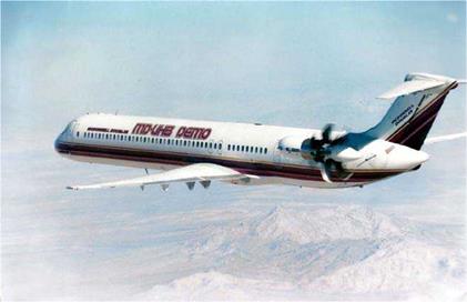
General Electric also flight-tested a Propfan on a McDonnell Douglas MD-80 between May 1987 and March 1988. This Propfan also had eight scimitar shaped contra-rotating blades, driven by the GE turbine engine with an un-geared, direct drive, unducted fan. This resulted in a greatly improved performance over a conventional jet engine. McDonnell Douglas named their Propfan a UHB (Ultra-high By-pass ratio engine) with scimitar blades. It had a by-pass ratio of 36:1, compared to 5:1 ratio of a Boeing 747’s JT5D engines. After four years of research and development at a total cost of around $100 million, McDonnell Douglas cancelled the project due to the high cost of the engine.

Pratt & Whitney joined forces with Allison to jointly test the P&W Allison Model 578-DX 20,000 static-pound thrust turboprop with a Hamilton Standard six-blade contra-Propfan of 11 feet 7 inches (3.53 m). The first flight of the MD-80 with the geared Propfan occurred on 13 April 1989, with all testing completed in a few weeks.

The extent of this author’s research shows the big American companies are no longer involved in any Propfan research for several years now. In the Commonwealth of Independent States (formerly Russia) research continued for a longer period. An Ilyushin IL-76 test-bed aircraft was used to test the Lotarev

Propfans

The McDonnell Douglas MD-80 flight-testing the P &W Allison Model 578-DX Propfan. Photo courtesy Hamilton Standard, Connecticut, USA.

contra-rotating tractor Propfan mounted on its number 2, (port inner) engine mount, with the first flight being made on 25 March 1971. The Yak-46, a 168-seat airliner with a pusher Propfan, is powered by two 24,690 pounds thrust ZMDB Progress D-27 Propfan with a first flight conducted circa 1995. The Antonov AN-180 was another type of passenger aircraft on the drawing boards around that time. It was due to fly around 1995 and was powered by two, rear-mounted tractor Propfan engines, the same type as found on the YAK-46.

Other types under test include the Antonov AN-70T designed as a military and civilian large STOL transport with a maximum all-up weight of 286,600 pounds (130,000 kg). It made a first flight on 16 December 1994 but its life was short-lived, due to its loss in a mid-air collision with its Antonov AN-22 chase plane on 10 February 1995. The second prototype first flew on 24 April 1997 with a third aircraft built in 1998. A 14,000 SHP Progress/Motor Sich D-27 turboprop engine drives each of the four, Aerosylva Stupino SV-27 turbine engines drive tractor, contra-rotating Propfans, which are different to the usual Propfan configuration. The fan has eight blades mounted on the front prop and six-blades mounted on the rear prop. Production was planned for this aircraft with 100 units being built for the Ukraine Air Force and 500 for the Russian Air Force, as of 1998. After a prolonged test program lasting sixteen years with many obstacles in its path, production started in 2012 for the Antonov AN-70. This places Russia ahead of the USA in Propfan technology, and with Propfan aircraft in service

Conclusion

The propeller’s development has come a long way since Blanchard first used a propeller on his hot air balloon way back in 1784, to the present day high-technology propellers. Constant-speed props with auto feathering and reverse thrust have been around for several years now and composite props are being used more and more on new aircraft types. Will the Propfan replace the present day turboprop transport aircraft? It may do so one day in Russia, but for the rest of the western world, turboprop aircraft with at least six-blade composite props will be flying for many years to come.

Propulsors

Other types of propellers still under development since the 1970s are the Propfan and Propulsor. Unlike the Propfan, which is a relatively new idea, Propulsors have been around for many years. A Propulsor is simply a propeller mounted inside a shroud. Although it has several advantages over conventional un-shrouded props, it has never been greatly utilized by aircraft designers, because of its suitability only for low-speed operations.

The Propulsor can trace its origin as far back as 1910, to the Bertrand Monoplane of French design. It had a single-engine driving a tractor and a pusher propeller, one at each end of the shroud. This was followed in 1932 by the Italian built

Propulsors

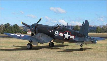
One of many flying examples of the Chance Vought F4-U Corsair taxiing out for take-off.

Stipa-Caproni, with a 120 BHP DeHavilland Gypsy III engine and Propeller, which were both mounted inside the shroud, which was a part of the fuselage. A more recent example of a Propulsor equipped aircraft appeared in 1996, in the form of the experimental Bell X-22A with four turbine engines driving separate tilt-vector propellers mounted inside shrouds. The US/German, VFW Rhein Flugzeubau/Grumman American joint venture Fanliner with two seats and a pusher Propulsor was another example. The Brooklands/Edgeley Optika from the UK, designed for the observation role, was showing good prospects for being a commercial success until ten of the twenty aircraft built was destroyed in a factory fire. Some could possibly be still flying. However, prior to this loss, the prototype’s first flight was made on 14 December 1979. The five-blade fixed-pitch propeller is powered by a 200/210 BHP Lycoming engine, giving the aircraft a cruise speed of 57-108 knots. Due to the propulsor, it is said to be the world’s quietest aircraft. Present day airships, such as those built by Airship Industries of the UK, have relatively low cruising speeds and are ideally suited to being propelled by the Propulsor type of engine