The power plant is an important component in all aircraft and no less so in helicopters. However, helicopters necessarily have a more complicated power transmission system than aeroplanes. In this chapter the choice of power plant is considered, along with the operating principles of piston and turbine engines and associated transmissions. Power plant control and instrumentation is also treated.
 |
The power source of a conventional helicopter must be able to drive a shaft, and have reasonable weight and fuel consumption in relation to the power delivered. This generally means an internal combustion engine: piston, rotary or turbine. Real engines always turn too fast for real rotors and some reduction gearing will be needed to transmit engine power to the various rotors and accessories. There have been some exceptions to convention. Numerous efforts have been made to fit rockets, ramjets or turbojets directly to the blades, or even to duct gases into the blades from the hull. The goal is to eliminate torque reaction and reduce weight. These alternatives are considered in section 6.28.
 |
All internal combustion engines work by burning fuel in air. This raises the temperature, causing expansion which can do work. In practice more power can be obtained if the air is compressed before the fuel burns. The turbine engine has dominated the helicopter power plant market for some time. The main advantage of the turbine is a very high power to weight ratio. The lightness comes from simplicity; the compression of air and the extraction of shaft power are both done by rapidly spinning blades. There is, however, a penalty for that simplicity which is that the fast moving blades suffer from profile drag. Just keeping the blades moving consumes power. When used at high power, the internal power loss is a small part of the overall power produced and the turbine is efficient. When used at lower power, the power lost in the blades does not reduce in proportion and so the efficiency falls. Small turbine engines tend to be inefficient because the Reynolds numbers at which small blades must operate will be less favourable. As a result there are very few small turbine engines and these tend to be used as APUs (auxiliary power units) that are only used intermittently. Although simple in concept, the turbine engine uses highly stressed parts and the initial cost is high.
Statically compressing air with a piston in a cylinder suffers much less power loss than dynamic means such as a turbine. This makes piston engines more efficient at partial throttle settings, hence their popularity in automotive applications. The energy released on each power stroke is finite and so a good way of increasing the power is to increase the RPM. The piston engine must handle the stresses raised by reciprocating that increase with the square of the RPM.
This limits the RPM available as a function of piston size. Very small piston engines used in models can run at over 25 000 RPM and produce an astonishing power to weight ratio, but this cannot be scaled up because of the forces involved. Another fundamental of piston engines is that the power available is a function of the charge that can be admitted to the cylinder. The cylinder volume is proportional to the cube of the bore whereas the cylinder head area, where the valves are, is only proportional to the square of the bore. As a result the small cylinder has the advantage because not only is the piston lighter, but more valve area is available in relation to the displacement. Thus in piston engines there is a power to weight advantage in using a lot of small cylinders rather than a few big ones. There is an optimum cylinder capacity for a given RPM. The difficulty is that in order to produce a lot of power, a lot of cylinders are needed and this causes practical difficulties in induction, exhaust, cooling and reliability, to say nothing of cost. During World War II aircraft engines having as many as 28 cylinders were built and these were immensely complicated.
At 400-500 kW the turbine and piston engine are about equal. For higher powers the turbine is to be preferred, whereas for lower powers the piston engine would be chosen. The power to weight ratio may not be as high, but if the fuel efficiency is good, the saving in fuel load may more than compensate. As a result, helicopter design has diverged into two camps. Large machines use two or three turbine engines and tend to use high disc loading because plenty of power is available. Small machines use piston engines and lower disc loadings.
In between the extremes there is some variability. The small single-engine turbine helicopter cannot use high disc loading because it must be designed to autorotate well. As a result it will not need much power and so the turbine will be heavily derated and have poor fuel efficiency. Unfortunately derating an engine does not lower the cost. Well-engineered piston machines can compete in this market simply by costing less to purchase and less to run. Frank Robinson has demonstrated this amply with the R-44, despite its elderly engine technology.
Unfortunately the aviation piston engine went into a period of stagnation for several decades after the arrival of the turbine, with the result that progress in piston engine development moved to the automotive sphere. This situation is now being remedied and a new generation of aviation piston engines will give helicopter designers some better solutions in light machines. In the automotive sphere fuel economy does not drastically improve performance because the fuel load is a relatively small proportion of the vehicle weight. In helicopters the fuel weight at take-off is limited by available rotor thrust. Thus an improvement in fuel efficiency in the helicopter will translate directly into either an increase in range for the same payload, or an increase in payload for the same range.
The power of the gasoline engine is controlled by an induction throttle, and when this is used, the effective compression ratio of the engine falls and with it the efficiency. The induction throttle reduces the manifold pressure and this opposes the motion of the piston during the induction stroke causing pumping loss. The power of the Diesel engine is not controlled with a throttle. There is negligible pumping loss and the compression ratio is always at its highest value. As only air is compressed, there is no risk of detonation and the compression ratio can be very high indeed. This makes
the Diesel fundamentally more fuel efficient than the gasoline engine as will be seen in section 6.14. Traditionally, however, the Diesel engine has been neglected in aviation although some Diesel powered aircraft flew in World War II. The automotive industry has dramatically improved Diesel performance in recent years and has shown that the Diesel engine lends itself very well to turbocharging. With modern technology the turbo-Diesel engine can equal the power of a gasoline engine for a given time between overhaul (TBO), but with better fuel economy so that the weight of engine plus mission fuel is actually less. Given that Diesel engines can run on AVTUR, which is significantly cheaper and less volatile than AVGAS, the economic and safety advantage of a Diesel engine is significant.
 |
Figure 6.1 shows the layout of the engine and transmission in a typical light piston – engine machine. Many light helicopters use an air – and oil-cooled engine originally designed for aeroplane use in which the crankshaft will clearly be horizontal. These typically have four cylinders arranged with a pair on each side. This arrangement is called a ‘flat four’ also known as a ‘boxer’ because the pistons on opposite sides appear to be sparring with each other. The propeller is replaced by the cooling fan and possibly a belt drive pulley. The cooling fan directs air through a series of baffles so that it passes round the cylinders. Some of the air is directed through the oil cooler. The centrifugal cooling fan of the Robinson R-22 is a conspicuous feature of the machine. The Enstrom has an axial fan.
Piston engines do not provide uniform torque because of the power impulses when each cylinder fires, and it is necessary to have some flexibility in the transmission to even out the power delivery. Even so, the transmission of a piston-engine helicopter has to be stronger to withstand the fluctuating torque. The use of anti-vibration technology in the drive train to smooth out the power impulses of piston engines with torsional tuned filters is in its infancy. Currently, flexibility in the drive train may be provided by using a belt drive and by mounting the engine on rubber blocks. The belts used are reinforced with polyester chords and have a tapering cross-section intended to run in vee-shaped grooves in the pulleys. Belt tension wedges the belt into the groove so that
|
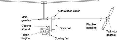
Fig. 6.1 The drive train arrangement used in a number of light piston-engine helicopters including Robinson, Enstrom and Schweizer models. The piston engine drives a cooling fan and a belt pulley. The belt drives a shaft between the main and tail gearboxes. The upper pulley contains a one-way clutch to allow the rotors to turn if the engine fails.
|
slipping will not occur. Machines vary in detail; the Robinson uses two double-vee belts, the Schweizer uses eight single belts, and the Enstrom uses a single Poly-vee belt about six inches wide. Belts can last as long as five years, but flying in dusty conditions causes more rapid wear.
The belt drive commonly does duty as the clutch. By slackening the belt tension, the engine can be started and warmed up without the rotors turning. When the engine is warm the belt tension is applied gradually so that the belt can slip in order to spin up the rotors smoothly. Once the rotors are up to engine speed the full flight tension can be applied. Starting the engine with the clutch engaged should never be attempted. In the Robinson the starter is powerful enough to turn engine and rotors, but when the engine fires the sudden speed increase could damage the main rotor blades. In an Enstrom the rotor blades are heavy and articulated and instead the result would probably be a burned-out starter.
The belt tensioning is performed in various ways. In the Robinson the shaft between the main and tail rotors is supported near the pulleys by a bearing that can be raised and lowered by a small electric gear motor. The flexible couplings in the shaft allow this movement. The belt tension is measured and the motor can only run until the correct tension is achieved. Some care is needed when operating the motor switch; rapid engagement will stall the engine. In the Enstrom the belt is tensioned by bringing in a jockey pulley against the flat outer side of the belt. This is mechanically operated by cable from a lever in the cockpit. When the drive is fully engaged a system of links passes over centre and maintains belt tension with no tension in the cable. In this system the pilot has better control of the clutch engagement force. In the Schweizer the belts are tightened by pulling out an idler pulley with a steel wire driven by a servo motor. The wire is permanently in tension. In all of these machines, the upper belt pulley drives the long shaft joining the main rotor gearbox and the tail rotor gearbox.
The pulley on the gearbox shaft has a one-way clutch inside it so that the engine can drive the shaft but the shaft cannot drive the engine. If the engine fails, or, worse still, siezes, the rotors can still turn freely so that an autorotation can be performed.
 |
As will be seen in section 6.19, turbine engines are found in two types. In the first there is only one rotating assembly and this is integral with the output shaft. No starting clutch is necessary because the starter motor spins the turbine and the rotor. In the preferred type of turbine engine there are two power turbines. The first generates shaft power to turn the compressor. The second turbine develops shaft power to drive the helicopter. Engines of this type are called free turbine engines because there is no mechanical connection between the first part of the engine, which is essentially a gas generator, and the second part that converts gas energy to shaft power. The gas generator may be spun with the starter motor even though the free turbine is locked by a rotor brake. In this way the engine can be started without the rotors turning. If the brake is released and the power is increased, the rotors will run up smoothly. The free turbine engine also has the advantage that the rotors can be stopped without stopping the engine. The turbine is set to idle power and produces minimal torque at the free turbine. The rotor can be stopped with the rotor brake.
The turbine itself is light and often mounted on or in the roof of the hull. Figure 6.2(a) shows the arrangement in the JetRanger. The power turbine gear train, through the autorotation clutch, drives the tail rotor shaft to the rear and the main rotor shaft to the front. The main rotor gearbox is resiliently mounted and the drive shaft is fitted with
two constant velocity joints to allow relative motion of the gearbox and the engine. In some machines the turbine drives only the main transmission as in Figure 6.2(b). In many machines twin engines are installed. In this case a pair of autorotation clutches is needed, one for each engine. Then either engine can fail and the remaining engine drives the transmission. The tail rotor drive must also come from the transmission.
The RRPM determines the rate of response to the controls and must be kept constant. It was shown in Chapter 3 that the power needed to drive the rotors at constant speed varies considerably with the attitude and flight regime. Governors and correlators are devices intended to make control of the throttle more or less automatic so that the pilot has less to do. The governor is a system using negative feedback to adapt the power
setting to the load placed on the engine. In contrast the correlator is a device using feedforward to predict the power setting necessary from the position of the collective lever. This may be done mechanically with a shaped cam on the collective linkage. The cam shape is obtained during tests of the prototype. Feedforward may also be applied electrically, in which case the collective lever is fitted with a position sensor. A correlator only gives an approximate control of RRPM since the position of the collective lever is only one factor affecting the power required. There is, for example, no compensation for air density or the degree of inflow through the rotor.
The gasoline engine is literally throttled to control its power. The induction passage is restricted and this is a stable process. If the engine speeds up, the pressure drop across the constriction will increase, dropping the induction pressure. If the engine slows down, the pressure drop across the constriction will decrease, increasing the induction pressure. Thus on a piston-engine helicopter governors are not essential and most machines just have a correlator. One school of thought suggests that it is better to learn to fly an uncorrelated machine because by manipulating the throttle a more thorough understanding of the power needed in different conditions is obtained.
Neither the turbine nor the Diesel has a throttle because the induction system is fully open at all times. As a result these types of engine will not hold their RPM unaided and a governor is essential. The governor is a system that compares the desired speed with the actual speed and uses the speed error to operate the power control to apply a correction. This is an example of negative feedback as described in Chapter 2.
The principle of the governor goes back to the first steam engines. In the centrifugal governor shown in Figure 6.3 a pair of weights are attached to a shaft driven by the engine such that they will fly out as speed increases. This is arranged to reduce the power so a set speed cannot be exceeded. The speed is set by a change to the spring tension applied to the linkage. If the spring tension is increased this tends to increase the power and the weights have to spin faster before they can produce enough force to reduce power.
In practice the engine revs will not be held perfectly stable because if more power is demanded the power control must be operated to provide it. The engine RPM must reduce slightly in order to create an error. Figure 6.4(a) shows that this is known as static droop. Static droop can be reduced by increasing the amount of power control movement for a given speed error. This effectively changes the gain applied to the speed
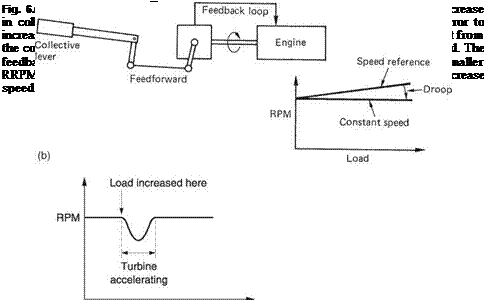
difference of the system. Increasing the gain will allow tighter control of speed but it also increases the chance that the system will become unstable so that it swings between too fast and too slow without stabilizing. A better solution is to combine governing and correlating systems so that there is both feedback and feedforward. Figure 6.4(b) shows how this is done. The power setting is determined by the sum of two signals. One of these is the feedforward signal from the collective lever. This provides approximately the right power setting. The second signal is the RRPM error feedback from the governor that slightly adapts the power setting to minimize the speed error. As most of the power setting is provided by the feedforward signal, the static droop will be minimal.
Piston engines are geared to the rotor and so run at near-constant RPM. The power delivered is changed with a change of torque and with a naturally aspirated engine this can be done instantly by adjusting the throttle or, in the case of a Diesel, changing
the amount of fuelling. This does not happen in a free turbine engine where only the power turbine is geared to the rotor. Instead, greater power will be supplied by an increase in the gas generator speed (N1) that delivers greater torque at the free turbine. N1 cannot increase immediately. It takes time for the spool to accelerate. As a result there will be a temporary loss of RRPM during the time taken to spool up. This is known as transient droop. Figure 6.4(c) shows transient droop following a step change in power demand. Turbocharged piston engines will also display transient droop as the turbocharger accelerates.
Transient droop may be reduced through sensing the collective lever velocity. During a landing, collective will be lowered and this will cause the gas generator to spool down. If the landing is to be rejected, the pilot will pull the collective lever up. A system sensing collective velocity will be able to start spooling up sooner than one which simply waits for the lever to come up to provide power demand.
If the collective lever is raised too far on a turbine machine, the result will be an overtorque condition as the governor maintains RRPM. However, on a piston-engine helicopter once the throttle is fully open, further application of collective will cause overpitching. Induced drag causes a reduction in RRPM. In a machine with a manual throttle the correct recovery from overpitching is to maintain full throttle and to reduce collective pitch momentarily to regain rotor speed. If such a machine were fitted with a correlator the act of lowering the collective pitch lever could reduce the throttle setting and delay the RRPM recovery. The operation of a governor would not be impaired because a reduction in RRPM would result in a large speed error that would fully open the throttle. In the optional governor system of the Robinson R-22 the throttle is controlled by a governor mechanism responding to RRPM. However, an additional system is fitted which prevents overpitching. If the throttle is wide open to recover RRPM but the rotor speed fails to respond, an additional servo motor reduces the collective pitch setting until the speed error has been reduced. The collective servo linkage is fitted with a slipping clutch so that in the case of a failure the pilot can override it. The first use of a mechanism to maintain rotor speed by lowering collective was by Flettner in the 282 Kolibri.
In practice a free turbine engine needs two governors, one for the gas generator spool and one for the power turbine. These will be part of the fuel control system. Either of them can limit the turbine fuelling to prevent overspeeding. The gas generator governor is used for starting, idling and shutdown, and is controlled by the throttle lever in the cockpit. For flight, the throttle lever is set to maximum so that gas generator RPM is no longer able to restrict fuelling. This results in acceleration of the gas generator spool and increased gas flow that brings the rotors up to flight RPM. The rotor speed is then controlled using the power turbine governor which limits fuelling as correct RRPM is reached.
The piston engine is now over 100 years old but modern designs still work in the same way as the machine built by von Otto.
Figure 6.5 shows a section through a typical horizontally opposed piston engine. The pistons slide to and fro inside the cylinders and they are joined to the rotating crankshaft by connecting rods. The connecting rods, generally abbreviated to con rods, must be able to swivel in the pistons, and this is the function of the gudgeon pin, which passes through the little end of the con rod. The other end of the con rod must have a larger bearing in it to fit around the strong crankpin. In the boxer engine the crankshaft
is constructed so that the pistons all move in and out simultaneously. The reaction due to accelerating the piston on one side is then balanced by that from the other side and vibration is reduced. The cylinders are not precisely opposite one another to give room for the crank web.
The large bearing in the connecting rod is called the big end. The aluminium pistons have slots fitted with rings which are springy metal strips. These press outwards against the cylinder wall and ensure a good pressure seal. In a piston engine four distinct stages are needed in the complete cycle, and in the four stroke or Otto cycle engine, the piston traverses the cylinder four times, which requires two revolutions of the crankshaft. The cylinder head is fitted with valves allowing fresh charge to enter the cylinder and burned charge, or exhaust, to leave. The valves are operated by a camshaft fitted above the crankshaft. This carries a series of rounded bumps called lobes. As the camshaft turns, each lobe presses against the flat end of a small piston-like object known as a tappet. In the tappet there is a swivel joint that connects to the push rod. This travels in a tube up the outside of the cylinder to a rocker in the cylinder head that pushes the valve open. When the cam lobe retreats, the valve is closed by the valve springs, which also push back the rocker, the pushrod and the tappet. When the valve is closed there must be a little slack in the pushrod, known as valve clearance, so that the whole spring pressure is keeping the valve shut.
Since the full four strokes require two crankshaft revolutions, the camshaft is driven through a 2: 1 reduction gear so the sequence of valve openings resulting from one camshaft rotation is spread over the two crankshaft revolutions. On the intake stroke, the inlet valve is opened and charge is drawn into the cylinder. On the compression stroke both valves are closed and the charge is squeezed into the remaining space above the piston. On the power stroke, pairs of spark plugs ignite the charge, and it burns and expands, driving down the piston and turning the crankshaft. On the exhaust stroke, the exhaust valve opens and the piston pushes out the spent charge. The cycle then repeats.
In practice momentum of the gases means that the valves operate at a slightly different time than this simple explanation would indicate. Figure 6.6 shows a typical valvetiming diagram. During the induction stroke the charge entering through the inlet manifold is travelling at high speed and cannot stop easily. The inlet valve is left open until after bottom dead centre (BDC). Momentum will continue to force charge into the cylinder so that extra charge can be admitted allowing more power to be generated.
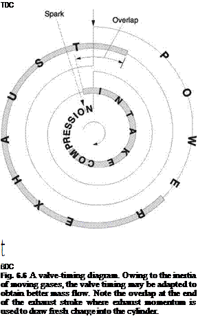 |
The exhaust valve opens before BDC so that the exhaust can start to accelerate out of the cylinder in time for the exhaust stroke. The exhaust gases leave at high speed, and at the end of the exhaust stroke the momentum of the gases will carry them onwards even when the cylinder is empty. This causes a reduction in pressure in the cylinder. The inlet valve is opened before the exhaust valve closes so that the momentum of the exhaust leaving will pull fresh charge in. This is known as valve overlap. Racing engines use camshafts having a lot of valve overlap to help charge transfer at high speed. This makes them very rough at lower speeds. Helicopter engines are required to have good throttle response over a limited RPM range rather than ultimate power, and will be fitted with milder camshafts.
The valve mechanism in early engines required an adjustment to take up slack in the pushrod as wear took place. A small clearance was left to allow the parts to expand without the valves being pushed open when they were supposed to be shut. If the valve clearance was excessive the valves would not open for as long, and power would be reduced. The mechanism would make a lot of noise. Tappet adjustment was frequently required to maintain performance.
In later engines a self-adjusting mechanism was devised. The tappet contains a small piston that drives the pushrod. Engine oil pressure is communicated to the tappet through a small drilling so that the piston will move until it has taken up the slack in
the valve train. When the camshaft opens the valve, the force is transmitted through the oil pressure. The drilling is too small to allow a significant amount of oil to be forced back out of the tappet. Hydraulic tappets are self-adjusting and the periodic maintenance is eliminated.
 |
Ignition of the charge is achieved by the generation of a spark between a pair of electrodes in the cylinder head. A very high voltage is needed to break down the insulation of the compressed charge so that a spark can occur. The high voltages present in ignition systems cause stress to the components, and as a result the ignition system is probably the least reliable part of the engine. This is overcome in aircraft engines by having a completely duplicated ignition system. There are even two spark plugs per cylinder, one for each ignition system. This also allows a small increase in power because the charge is ignited in two places at once.
In cars, the high ignition voltage is generated by an induction coil driven by the electrical system. If the electrical supply is cut off the engine stops. This is not reliable enough for aircraft, and these use an alternative system that generates its own electricity directly from engine shaft power using a rotating magnet. This magneto-dynamic ignition unit is invariably known by the abbreviation of magneto. In a magneto system the engine will keep running even if the electrical system of the helicopter has totally failed. A pair of magnetos are fitted on the back of an aircraft engine, driven by the gear cluster that drives the camshaft and the oil and fuel pumps. When the aircraft engine is mounted backwards in a helicopter, the magnetos can be found adjacent to the cockpit firewall.
The principle of operation of the magneto is based on the same physics as electricity generation. When current flows through a coil of wire, it generates a magnetic field. The field can be amplified by winding the coil around a soft iron core. If the magnetic field passing through a coil is constant, there is no effect, but if the field changes, a voltage proportional to the rate of change of flux is induced. The two phenomena described above combine to give a coil the property of inductance. An inductor is a sort of magnetic flywheel. A mechanical flywheel stores kinetic energy proportional to the square of the speed. An inductor stores magnetic energy proportional to the square of the current. In the same way that a flywheel resists changes of speed, an inductor resists changes of current.
Imagine an inductor with a current flowing through it. If some external resistance attempts to reduce the current, the magnetic flux in the coil is reduced. The falling flux induces a voltage in the coil that attempts to increase the current. On the other hand if something attempts to increase the current, the magnetic flux will increase, and the change of flux in the opposite direction will induce a voltage that opposes the current. As a result the inductor tries to keep the current passing through constant.
Figure 6.7 shows the construction of a magneto. The input shaft turns at camshaft speed and carries a powerful permanent magnet. As the magnet turns its magnetic field passes through stationary poles in alternate directions. Around one of the poles is a winding of thick copper wire. The ends of this coil can be shorted out by a pair of contacts, known as points, operated by a cam on the input shaft. A capacitor is fitted across the points that are closed when the magnet flux in the stationary pole is changing from one direction to the other. The changing flux induces a voltage in the coil, but the coil is shorted out so there is very little resistance. The coil builds up a high current at a rate determined by the inductance.

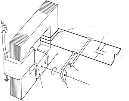 Magnet
Fig. 6.7 eto generates its own electricity and so is potentially more reliable than an ignition system
using the aircraft’s electrical supply.
When maximum current is reached, the cam opens the contacts. The inductance attempts to keep the current flowing, but it cannot pass the open points. The only place the current can go is through the capacitor. As the capacitor charges up, the current reduces. This reduces the inductor flux and increases the induced voltage. When the current finally stops flowing, the capacitor is charged to a high voltage. The magnetic energy has been exchanged for electrical energy stored in the capacitor. The voltage on the capacitor now reverses the current, which builds up in the inductance. The current keeps flowing after the capacitor voltage has fallen to zero and charges the capacitor up in the reverse direction. The inductor and capacitor form a resonant circuit where the energy repeatedly exchanges between the inductor and the capacitor and an alternating current flows in the windings. The same effect is achieved mechanically in a tuning fork.
As the capacitor is quite small, the frequency of oscillation is quite high, and the rate at which the current changes is also high. Thus a high rate of flux change is achieved in the inductor. A secondary coil consisting of many turns of fine wire is wound on top of the first coil. The rapidly alternating flux induces a very high alternating voltage in the secondary coil, and this results in a rapid succession of sparks at the plug electrodes. The sparks continue until the magnetic energy is dissipated. In a multi-cylinder engine, this high tension (HT) current is directed to the appropriate cylinder by a rotary switch called a distributor on the end of the shaft. There is no mechanical contact in the distributor; the metal parts come close enough for the HT to jump across the gap, so in fact there are two sparks in series, one at the plug and one at the distributor.
The capacitor is a vital part of the system, because without it the current would have nowhere to go when the points open, and most of the magnetic energy would be dissipated in a spark at the points, which would then be rapidly eroded away. The spark in the cylinder would then be very weak. This can happen if the capacitor becomes disconnected or fails open circuit. If the capacitor fails short circuit the points are bypassed, and no spark will be produced at all. This type of failure is rare.
The HT wiring to the spark plugs needs to be well insulated so that the HT does not jump to the nearest piece of metal instead of going to the plug. At high altitude the reduced air pressure reduces the insulating ability of the air, and as a result the ignition leads must have somewhat better insulation than those found in cars. Part of the pre-flight check is an inspection of the condition of the HT leads. Needless to say they should not be touched when the engine is running.
Whilst the magneto has the advantage that it is completely independent of the helicopter’s electrical system, it does suffer from one disadvantage. When starting, the engine speed is low, and the rate of change of flux in the magneto will be correspondingly low and a poor spark results. One solution to this problem is a device known as an impulse coupling which is basically a torsion spring in the magneto drive shaft. The presence of the permanent magnet makes the torque needed to rotate the magneto vary with the angle of rotation. This can easily be demonstrated by attempting to turn a bicycle dynamo by hand. At starting speed, when the torque is large, the spring in the impulse coupling is wound up as the magneto lags behind the shaft. As the torque falls, the spring tension is released, and the magneto is temporarily turned faster than the shaft. This allows a larger spark to be generated. A further use of the impulse coupling is that the lag delays the time at which the spark is generated. Under normal conditions, the spark is supplied a little before top dead centre (TDC) in order to allow the charge time to start burning before the power stroke. At low starting RPM, the advanced spark might cause the engine to kick back, or fire during the compression stroke. The delay of the impulse coupling prevents this happening. At normal operating speed the torsion spring does not have time to twist and the magneto runs at constant speed with the correct timing.
Dual ignition systems are provided to increase the reliability of the engine. This reliability increase is only present if both ignition systems are working properly. Part of the pre-flight check is to test the ignition system. This is done using the ignition switch. As the magneto is self-contained, the only way it can be switched off is by shorting out the points. The ignition switch is connected across the points and the magneto is switched off by closing the ignition switch contacts. This is a safer approach since a broken wire from the ignition switch will not stop the engine. The ignition switch is constructed so that either or both magnetos can be switched on. In aircraft the ignition switch may have a further position to operate the starter, but this is not used in helicopters. Instead the starter button is fitted on the end of the collective lever where it may be operated by the pilot without letting go of the controls.
When the engine is warm, the dual ignition may be tested. At a specified RPM, the ignition switch is turned from ‘both’ to ‘left’. This disables the right magneto. The result should be a slight reduction in RPM, known as a magneto drop, because only one spark is being generated per cylinder. The drop is normally that which is measured after 5 seconds running on one magneto. The engine is run on both systems again for a short time to clear any fouling which may have built up on the plugs whilst they were out of use. The switch is then set to ‘right’, when an identical drop should be obtained. If the drops are grossly different or do not occur, there is a problem which must be rectified before flight.
To take an example, if on switching from ‘both’ to ‘left’ there is no drop, either the right magneto was not working or it has not been switched off due to a broken wire. Switching to ‘right’ will show which. If the engine cuts, the right magneto is inoperative. If a drop is obtained, the right magneto is permanently on due to a wiring fault. This can be proved by switching off the ignition. If the engine continues to run, the wire to the ignition switch is broken. The engine can be stopped by the idle cut-off as normal.
If the drops are not identical, one ignition system is working better than the other for some reason. If only an RPM loss is noted, the different drop could be due to a timing difference between the magnetos. If one magneto gives a larger drop and a misfire, consideration should be given to the possibility of a failed spark plug or capacitor or a fractured HT lead.
The cylinders are numbered from what would be the front in an aircraft, which in a helicopter corresponds to being numbered away from the drive pulley. In a Lycoming engine mounted back to front in a helicopter, the odd numbered cylinders are on the port side. The sequence of power strokes is designed to reduce torsional stress in the crankshaft by firing cylinder pairs alternately. This gives the firing order of 1-3-2-4.
 |
The starter is basically a powerful electric motor used to turn the engine. A reduction gearing system is needed so that the starter can develop enough torque to overcome the engine compression. A small pinion on the starter engages with a large ring gear on the engine flywheel. The gears are only engaged during starting. This can be done by a helical thread mechanism that screws the pinion along the motor shaft or by a solenoid that slides it. In the latter type a one-way clutch prevents the engine driving the starter. Recently geared starter motors have become available. These have a high speed electric motor and a reduction gearbox and are lighter than conventional starters and consume less current. The weight saving may be compounded because they allow a smaller battery and thinner wiring to be used.
The motor must be quite powerful, and it will require a current of several hundred amperes to operate it. In order to minimize power loss in the cables, these run direct from the battery to the motor. This current is beyond the capability of a switch, and a relay is used. The starter button on the collective lever switches a small current through a solenoid coil, and this attracts the solenoid armature, sliding the starter gear into engagement with the flywheel and pulling the main motor contacts closed. Normally the starter motor gear is driven through a one-way clutch so that it can run at high speed when the engine fires without damaging the starter motor. A warning light is fitted which should go out if the starter button is released. If it does not the starter may still be engaged.
If the starter fails to operate, this could indicate a faulty solenoid. It is generally possible to hear the solenoid operating. If the solenoid chatters or vibrates this indicates a loose battery connection or a discharged battery.
The starter motor dissipates a lot of heat when starting, and if the engine does not start promptly because it is flooded or vapour locked, prolonged cranking will flatten the battery and overheat the starter motor. It is better to allow a cooling period between starting attempts than to burn out the starter motor. The starter motor should never be operated when the engine is running as engaging the starter pinion with the fast turning gear on the flywheel could remove teeth. The engine must be allowed to come to a complete halt before making a further starting attempt.
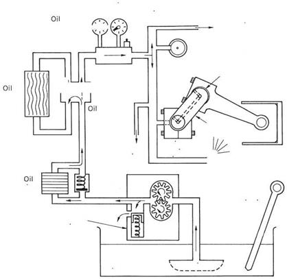 The oil system is responsible for lubrication and cooling of the moving parts of the engine. Heavy forces are involved in the connecting rods and crankshaft bearings, and if metal-to-metal contact took place the life of the parts would be very short. Oil possesses viscosity, which is a resistance to flow. If viscous oil is pumped between two surfaces it can carry a load without them touching because the viscosity resists the oil being squeezed out. The relative movement of the surfaces causes shearing of the oil. Shearing a viscous liquid develops heat, and this heat load adds to the heat picked up where the oil is used to cool parts of the engine. An oil cooler is necessary to control the oil temperature.
Figure 6.8 shows a typical engine oil system. Oil is held in the sump below the engine. The sump contains a filler neck whose cap holds a dipstick so the oil level can be checked. This should be done before flight. Oil is drawn from the sump through a strainer to prevent particles of dirt from damaging the pump. The pump may consist of a pair of meshing gears driven from the camshaft/magneto drive cluster at the rear of the engine. The capacity of the pump exceeds the requirements of the engine, and surplus oil is returned to the sump by a spring-loaded relief valve that opens when the correct
Oil pressure gauge and switch

temperature b-o-l
gauge
Camshaft
thermostatic

Crank
Dipstick
Pressure relief valve
Oil sump
Fig. 6.8 Lubrication system for a typical piston engine. See text for details.
oil pressure is reached. The oil then passes through a filter that removes microscopic particles of metal due to engine wear and combustion products that have found their way past the piston rings into the oil. The filter needs to be replaced periodically. If the filter becomes clogged, a spring-loaded valve opens allowing oil to bypass the filter.
The oil next passes to the oil cooler. This is a small heat exchanger that is often fitted in the engine cooling baffles so that it gets a cold air feed from the engine driven fan. The cooler is bypassed by a thermostatic valve that is open at low temperatures to allow the oil to warm up quickly. The valve can also be forced open by oil pressure if the cooler blocks up. At the outlet of the cooler the oil is ready to be fed to the engine. At this point the oil pressure and temperature are monitored and displayed on gauges in the cockpit. Some of the oil is fed to the main crankshaft bearings. The crankshaft is hollow and oil is pumped in from the main bearings and flows to lubricate the big ends. The connecting rods may also be hollow and oil carries on up the rods to lubricate the little end. An oil jet is drilled in the top of the connecting rod to spray oil on the piston for cooling and to lubricate the cylinder wall. Oil is also supplied to the camshaft bearings and the valve mechanism as well as to the gear train driving the camshaft and the magnetos. The oil will eventually fall back into the sump.
The engine oil has a finite life primarily because it builds up an increasing load of acids, which are by-products of combustion, and water from condensation. Oil is characterized by its viscosity. Viscosity is measured by the time taken in seconds for a standard quantity of oil to flow through an orifice standardized by the Society of Automotive Engineers (SAE) at a standard temperature. Oil may also be classified by a commercial aviation number that is twice the SAE number.
The viscosity of oil falls with increasing temperature. So-called multi-grade oils have a smaller viscosity loss with temperature. The correct viscosity of oil is essential and it must be used at the correct temperature. If the oil is too viscous or used at too low a temperature, it may not flow readily to all the necessary parts of the engine. If the oil is too thin or used at too great a temperature, it may be squeezed from bearings and permit contact. The engine oil must be warmed up before flight so that correct lubrication is achieved when full power is demanded.
The flight manual will specify the viscosity of oil that must be used in temperate conditions. A mandatory placard on the machine adjacent to the filler will state the viscosity needed. If the machine is consistently operated at elevated ambient temperatures, it may not be possible to keep the oil down to the required temperature. In this case thicker oil will be used which will thin down to the right viscosity at the elevated temperature. In a similar way if the machine is to be used in cold conditions the oil may run too cold and thinner oil will be specified to get the right viscosity at a lower temperature. It is important that the oil level is checked regularly and kept topped up with the same type of oil. Oil grades should not be mixed and it is better not to mix brands. Oils contain a host of additives to improve performance and sometimes the additives in one kind of oil react with those in another. Turbine engines need oil with different additives and viscosity. Turbine oil cannot be used in piston engines.
The oil pressure and temperature gauges tell a great deal about the health and working conditions of the engine and should be monitored regularly as part of the pre-flight check and whilst airborne. On starting the engine, it may take some time for oil pressure to be established as the oil is cold and thick and the pump has difficulty dragging it from the sump. Expect the delay to be longer in cold conditions. Generally if oil pressure has not established in 30 seconds the engine should be shut down and the cause investigated.
When cold the oil resists flowing through the engine and once pressure is established the pump has no difficulty supplying enough pressure. Paradoxically, once the pressure has established, it may become excessive in cold conditions or if using straight
(non-multi-grade) oil in a new engine. In this case the engine revs must be kept to a minimum after starting until the oil has warmed up. Another cause of excessive oil pressure at idle is if the relief valve has stuck. In any case of excess pressure, engine revs must not be increased as a further increase in pressure could burst the oil filter or the cooler.
In a hot engine the oil flows more freely and worn bearings will increase the oil flow. At idle speed the oil pump may not be able to meet the flow demand and the pressure will fall. Thus low oil pressure with hot idle may indicate bearing wear.
After a cold start, the engine should be run on the ground until the oil temperature has reached a minimum level for flight. If it takes an excessive time for this temperature to be reached the thermostatic valve in the oil cooler could be stuck and making the cooler work continuously.
Sudden and total loss of oil pressure in flight is rare and will be due to a mechanical failure such as a sheared pump drive or a burst pipe. The engine will be destroyed unless it is shut down immediately. If a suitable landing site is available, the engine should be stopped and an autorotating landing will be needed. A conscious decision to autorotate is safer than trying to land using power because without oil the engine could sieze up without warning and this might occur in the avoid curve. If no suitable forced landing site is near, it will be necessary to sacrifice the engine in order to attempt to fly to safety. Flying at minimum power speed will buy time.
A more likely fault situation in flight is where the oil temperature slowly rises and the oil pressure slowly falls. This is an indication of oil loss due to a leak or oil being burned in the cylinders. A landing should be made promptly so that an investigation can be made.
When assessing the oil pressure and temperature gauges, the stress the machine has been under should be considered. Following a lengthy climb at maximum all up weight (MAUW) one might expect hot engine oil. The stress on the machine would be reflected in elevated transmission oil temperature and cylinder head temperature. If all of these readings are high, the machine is being driven hard and should be flown in a way that will reduce the power requirements.
On landing the engine should be run at idle for a short while in order to cool it. If this is not done oil inside the engine will be exposed to heat that it cannot carry away and the oil could be carbonized and lose effectiveness. This is known as heat soak.
Engines produce power by burning charge. The purpose of the carburettor is to mix air and fuel to create charge. Charge will burn over the following range of fuel/air mixes. A ratio of 1 part fuel to 8 parts air is called a rich mixture, and not all the fuel will be burned. A ratio of 1:20 is called a lean mixture and not all of the oxygen will be burned. A ratio of about 1:12 is called a stoichiometric ratio as there is just enough fuel to combine with all the oxygen.
Clearly a chemically accurate ratio will give the most power and a lean mixture will give the best fuel economy. Unfortunately it is not possible to take full advantage of this because of a number of practical considerations. At high power the engine temperature cannot be kept at a safe level unless a rich mixture is used. The surplus fuel absorbs heat by evaporation.
The four-stroke engine compresses the charge before combustion to increase the power output. The greater the compression ratio, the more power can be released. When charge is ignited it should proceed to burn smoothly as a flame front travelling
away from the spark plug. Unfortunately when charge is compressed the temperature will be raised and it can detonate instantly when ignited. This causes a rapid pressure step that creates shock waves travelling through the engine. A metallic ringing noise called ‘pinking’ or knock can be heard. If sustained, engine damage will result.
The ability of a fuel to resist detonation must be matched to the compression ratio of the engine it will be used in. The detonation resistance of fuel is measured in a special variable compression test engine. The fuel under test is used to drive the engine and the compression is increased until detonation commences. The engine is then run on iso-octane, a relatively detonation resistant hydrocarbon, and this is steadily diluted with heptane, a detonation prone fuel, until detonation commences. The percentage of octane at which this takes place is the octane number of the fuel. Since the test was devised, more detonation resistant fuels have been developed, and the scale has been extended above 100 by extrapolation.
Using fuel of inadequate octane number for the engine causes damage through detonation. The machine carries mandatory placards adjacent to the fuel fillers stating the octane number of the fuel that must be used.
A rich mixture helps to prevent detonation by reducing the temperature increase during compression. Fuels are often specified by two octane numbers; the second is for a rich mixture. For example, many piston helicopters burn 100/130 LL fuel. At normal mixtures this is 100 octane, but at full rich mixture it is 130 octane. LL stands for low lead. In the 1920s it was discovered that the addition of tetra-ethyl lead to fuel increased the octane number. Decades later it was proved that the resultant lead pollution was slowing the rate of brain development of children living near busy roads and less damaging alternatives have had to be found.
Whilst fuel of inadequate octane rating causes damage, occasional use of higher octane fuel is acceptable. Prolonged use of high octane fuel may result in spark plugs being fouled by the octane-boosting additives. No power increase will be observed because the power output is determined by the engine design, particularly the compression ratio.
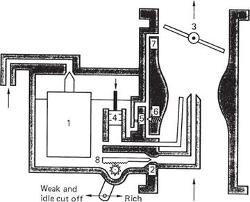
The carburettor has to mix the air and fuel in the chosen proportion. Figure 6.9 shows that it is a fairly simple device. Engine power is controlled by throttle (3): a disc that pivots in the intake tract. With the throttle wide open, the pressure in the inlet manifold will be nearly atmospheric, whereas with the throttle closed down to the idle position, the manifold pressure will be near zero. Manifold pressure is displayed on a gauge in the cockpit as it indicates the proportion of maximum power the engine is producing. The pilot needs to know how much reserve power is necessary before committing himself to a manoeuvre needing higher power: a procedure called a power check.
The result of throttling the engine is to reduce the flow of air through the carburettor. The fuel flow must remain proportional to the mass flow. This is done by the creation of a small constriction or venturi in the inlet tract. The air must go faster through the smaller cross-section. This increases the dynamic pressure of the air. As the static and dynamic pressures sum to a constant, the static pressure must reduce, as described by Bernoulli’s theory. The reduction in static pressure causes a pressure difference across the fuel in the carburettor body making it flow through a metering orifice or jet (2) and mix with the air. Clearly the depth of fuel could affect the pressure and the carburettor has a float valve (1) that admits fuel as it is used to prevent the level falling.
The system is self-balancing, because greater airflow causes greater suction at the venturi and increases the fuel flow. If the throttle is opened suddenly, the fuel inertia prevents a rapid increase in fuel delivery and the mixture will weaken momentarily. Weakening is prevented by the action of a small pump (4) that produces a jet of fuel when the throttle is opened quickly.

|
To inlet valves
(a)
From air cleaner
|
|
|
To inlet valves
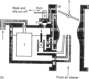
Fig. 6.9 ettor is a simple device which uses a venturi to create a pressure drop that will suck fuel
from a jet. The jet may be variable (a) for mixture control, or this may be done by air bleed changing the pressure exerted on the fuel (b).
|
|
When the engine is at idle, the throttle will nearly be closed. The minimum throttle opening is set by throttle stop screw that prevents the engine inadvertently being stopped. With the throttle closed the airflow through the venturi is very small and insufficient to draw fuel. As the throttle disc reaches the closed position it admits low manifold pressure to a drilling in the side of the tract. This draws fuel from the float chamber through the idle jet (5), and air from the idle mixture screw (6). In effect a miniature carburettor is created to handle the small charge flow at idle.
As altitude increases, the air density falls but the fuel density doesn’t. The carburettor tends to produce a richer mixture than necessary. This is overcome by fitting a mixture control. There are two ways of controlling the mixture. In the first, shown in Figure 6.9(a), a needle valve (8) is placed in series with the main jet and changes the resistance to fuel flow. Placing the mixture control to idle cut-off stops the fuel flow altogether and stops the engine. In the second method, shown in Figure 6.9(b), low pressure from the inlet manifold is applied to the float chamber by a valve (9) to oppose the venturi suction and reduce the fuel flow. Idle cut-off is achieved by allowing full manifold pressure into the float chamber. There is no resultant pressure across the fuel and flow ceases.
The carburettor is a simple device but it does suffer from one major problem. The evaporation of fuel requires heat, and in the absence of any other source the heat is taken from the incoming air and the body of the carburettor. In humid conditions this can lead to the formation of ice in the carburettor venturi. The rapid flow around the edge of a nearly closed throttle and subsequent expansion into the low pressure in the manifold duplicates the mechanism of the domestic refrigerator and can cause throttle icing. This is particularly dangerous because at low power on a descent the ice build-up will not be noticed. When full power is required to arrest the descent it will not be available. The engine will artificially be throttled by ice and the mixture will be unpredictable.
The traditional approach to icing is to supply hot air to the carburettor intake. This is conveniently obtained by drawing air over the exhaust system. Unfortunately hot air is less dense and reduces engine power so it cannot be used all the time. The pilot is therefore provided with a control to select the carburettor heat. If there is the slightest suspicion of icing, full heat should be applied. If engine smoothness and power improve, there was icing. It may be necessary to apply heat periodically or continuously to control icing. If power reduces, there was no ice and the engine is running on air that is too hot.
Heat control requires a disciplined approach because the effects of an incorrect decision may not be evident until it is too late. Heat should be used for descents, but the prolonged use of heat on the ground is to be avoided if the hot air is not filtered. Some machines, such as the Robinson R-22, have a carburettor temperature gauge which is useful for deciding if heat is necessary. Air temperature has less effect on the probability of icing than does humidity. Carburettor heat has another problem which is that it affects interpretation of the manifold pressure gauge. This will be considered in section 6.14.
In comparison with modern automotive practice, in which electronic fuel injection is used almost exclusively, the aviation carburettor is a museum piece.
In a fuel injected engine there is no carburettor. The fuel is sprayed into the inlet manifold just before the inlet valve by a fuel nozzle. There is one nozzle per cylinder. The use of fuel injection has a number of advantages. Fuel vaporizing takes place in
a hot part of the engine where icing cannot occur. A fuel injected helicopter needs no hot air system and full power is always available with a corresponding increase in safety. Throttle response is instant. The flow measuring venturi restricts airflow much less than a carburettor, and maximum power is increased.
There are two types of fuel injection system. In mechanical systems, the fuel delivery is continuous and is determined by the fuel pressure in the fuel manifold (also known as the fuel distributor or flow divider). Fuel manifold pressure is displayed on a gauge in the cockpit, often combined with the inlet manifold pressure gauge. In electronic systems, the fuel delivery is controlled by a solenoid valve, one incorporated in each nozzle. In this case the fuel pressure is held constant relative to manifold pressure and the amount of fuel delivered is determined by the period of the pulses that operate the solenoids.
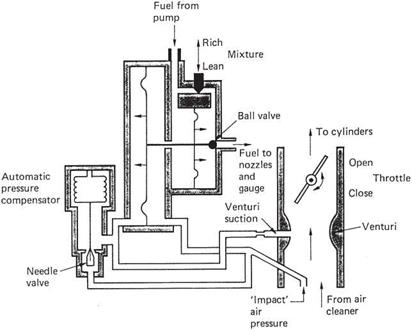
The engine power is controlled as usual by a throttle disc in the inlet duct. In a mechanical system, a small venturi is created in the duct and the suction created is a function of inlet airflow. The fuel pressure is made proportional to the venturi suction in the fuel control unit shown in Figure 6.10(a). The pilot’s mixture control changes the balance in the fuel control unit and the idle cut-off function stops all fuel flow.
The only real drawback of mechanical fuel injected engines is that hot starting can be difficult because residual engine heat vaporizes the fuel in the pipes leading to the nozzles. The solution is to purge the pipes and cool them with fresh fuel by running the boost pump for a few seconds with the throttle ‘cracked’ (partially open). The surplus fuel will flow into the inlet manifold and must be purged by operating the starter with the ignition off and the throttle wide. The throttle is then returned to idle, ignition is switched on and the starter operated again. Once the engine is running the boost pump is switched on again as a flight backup for the mechanical pump.
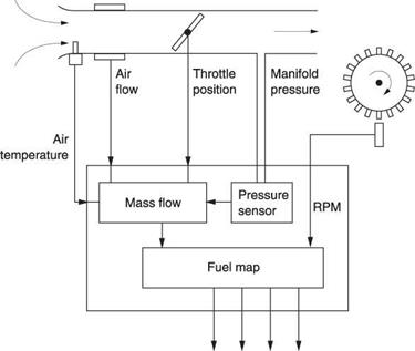
In electronic systems, a signal processor computes the correct amount of fuel to inject. It does this based on the mass flow of air into the engine. Figure 6.10(b) shows that engine RPM is measured by sensing ignition pulses or with a sensor adjacent to a toothed wheel. In the inlet tract, the air mass flow may be measured by a hot-wire sensor. Alternatively the manifold pressure may be measured. The air temperature is also measured to compensate the computation. As a result the mixture is always correct and no human intervention is required. In automotive applications, there is only one processor. This represents a single point of failure not acceptable in aviation. However, it is quite possible to provide one processor per cylinder each having its own sensors. It is also necessary to provide electrical power to the fuel injection system even if the main electrical power system fails. This is easily done using power-generation windings in the magnetos as is the practice in motorcycles.
Whilst the fine nozzles of injection systems are more prone to blockage than a carburettor, with proper filter and fuel management this is not an issue.
The power a piston engine can develop is a function of the charge burned on each power stroke. Clearly a greater charge can be obtained by using a larger engine, but this will be heavier, negating some of the increase in power. A more efficient way of increasing the power is to get more charge into a given engine.
In a naturally aspirated engine, when the piston goes down on the intake stroke, charge is pushed into the cylinder by atmospheric pressure. The elements of the induction system such as the air cleaner, the venturi and the valve stems all impede the flow.
|
|
|
|
|
|
|
|
|
Fig. 6.10 (a) A mechanical fuel injection system virtually eliminates intake icing because most of the induction system contains only air. (b) In an electronic fuel injection system the mass flow is calculated to determine how much fuel to inject. This is controlled by the length of time for which the injector solenoids are energized.
|
|
|
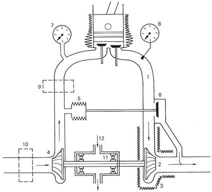
Fig. 6.11 The turbocharger uses energy from the exhaust gases to increase the mass flow of the induction process. See text for details.
|
As altitude increases, atmospheric pressure reduces, so there is less to push the charge into the cylinder. The air density falls, so the mass of the charge is even further reduced. Without some help, the piston engine simply cannot breathe at altitude. Any device which forces more charge into the cylinder is a supercharger. These were originally mechanical pumps driven by the engine crankshaft. Later it was realized that the residual energy in the exhaust could be harnessed to drive the pump. This is the principle of the turbocharger shown in Figure 6.11.
Exhaust gases 1 pass through a turbine 2 before passing to the atmosphere. The presence of the turbine extracts energy from the exhaust gases, lowering the temperature and the pressure. The pressure drop needed to make the turbine work means that the pressure in the exhaust manifold, known as back-pressure, is higher than normal. Heat insulation 3 is usually needed around the exhaust turbine. The exhaust turbine drives a centrifugal compressor 4 that takes in air through the air cleaner 10 and forces it into the induction system. The boosted induction pressure is displayed on the boost gauge 7 and increases the charge entering the cylinder. Back-pressure in the exhaust prevents the charge blowing straight through during valve overlap.
The turbocharger is a simple device, but it may turn at over 20 000 RPM. The stresses due to this rotational speed are enormous, yet the material of the exhaust turbine also has to withstand the elevated exhaust temperature due to raising the power output.
Turbochargers only became economic when suitable materials were found which could withstand this kind of treatment for a reasonable lifespan.
A turbocharged engine without some form of control system could be dangerous. The more power the engine develops, the more turbocharging can be achieved, which develops even more power and so on. In practice this is prevented by a system controlling the induction pressure. The exhaust turbine may be bypassed by a valve known as a wastegate 6. If the induction pressure exceeds the design limits, the wastegate actuator 5 begins to operate to cut the power received by the exhaust turbine. At sea level the air is sufficiently dense that only a little exhaust energy is needed for charging and the wastegate will open relatively wide. As the machine climbs, air pressure and density fall, and the induction pressure tends to fall with it. The control system senses the fall in pressure and starts to close the wastegate. This diverts more of the exhaust through the turbine and drives the compressor faster until the pressure is brought back to the sea-level value. Clearly engine power is maintained with increasing altitude until the wastegate is completely closed, and after that, power will naturally fall off.
The compression process in the induction system raises the air temperature and reduces its density. A further power increase can be obtained by cooling the induction air between the turbocharger and the engine. This is done by an intercooler 9 that is a form of heat exchanger. These are uncommon on helicopters because of the extra complexity, but provided the weight is moderate the effects are beneficial.
It is sometimes claimed that turbocharged helicopter engines are less reliable because the turbo stresses the engine. Whilst this is true of racing car engines, where brute power for one race is the goal, the helicopter engine does not use the turbo so much to increase power as to maintain the same power under all conditions. This can only be a good thing.
From the pilot’s point of view the turbocharger does not cause any difficulty. In the cockpit the only change is that the figures on the manifold pressure gauge can go above sea-level pressure. There may be a boost pressure limit denoted by a red line. An overboost warning light is sometimes found. Turbocharged machines display transient droop. When more manifold pressure is called for, the wastegate has to close down to increase the turbo power, and it takes a finite time for the turbocharger RPM to increase.
Part of the pre-flight check is to inspect the turbocharger for mounting security (when it is cold!). The rotor bearing 11 needs a supply of oil from the engine oil system 12, and the small pipes should be checked for cracks or leaking unions.
Power loss due to high altitude or air temperature has less effect on a turbocharged machine and when in-flight power checks are performed it will be seen that there is more reserve power than in a naturally aspirated machine.
In air-cooled gasoline engines, the cylinder head temperature (CHT) gauge is used after starting to determine if the engine is warm enough to run properly with the rotors engaged. After flight it is used to check that the engine has cooled down sufficiently to prevent heat soak when it is switched off. In flight CHT rises with the power the engine is asked to develop and if it reaches the red line on the gauge the power should be reduced. If the CHT reaches an unreasonable value for the applied load the possibility of an excessively weak mixture or a blockage or other defect in the cooling should be considered.
In water-cooled engines there will be a water temperature gauge which indicates the temperature of the water leaving the engine. Temperature should climb steadily after starting and level off at the designed temperature. This will often be above 100°C since the coolant is not actually water but a mixture of ethylene glycol and the system is also pressurized so that the boiling point is raised.
On turbocharged machines an exhaust gas temperature (EGT) gauge (8 in Figure 6.11) may be found. This will also rise with engine power and the gauge may be red-lined to protect the exhaust valves and the turbocharger.
The oil pressure gauge indicates the performance of the oil pump. If the pump can meet the flow demanded by the engine, the pressure will be normal. If it cannot, the pressure will fall. Low pressure could be due to a worn pump or bearings, but it could also be due to the oil being extremely hot so that it is thinner and runs through the engine faster than the pump can deliver it. The oil pressure and temperature gauges should be read together to form a meaningful picture.
The manifold pressure gauge and the fuel pressure gauge in a fuel injected gasoline engine both indicate the proportion of full power being developed and so the reserve power can be deduced. The fuel pressure indicator is also calibrated in fuel consumption rate so that the flying time can be calculated from the fuel load.
Manifold pressure or boost gauges are calibrated in absolute pressure, i. e. relative to a vacuum. In a naturally aspirated engine the manifold pressure cannot go above atmospheric and it is technically incorrect to refer to it as a boost gauge. In the presence of a turbocharger the manifold pressure can go above atmospheric and then the term boost gauge is correct. For a given induction air temperature, the boost pressure is proportional to the power the engine is developing. However, changing the air temperature changes the air density and so the mass flow, which really controls the power, will be different for a given boost pressure.
Consequently if carburettor heat is in use, the air entering the engine will be less dense and so less power will be developed for a given boost reading. If the engine is derated by setting an induction pressure limit, adhering to that limit with carburettor heat selected will result in unnecessarily limiting the available power. It is the actual power developed which determines the stress on the engine, not the induction pressure. With carburettor heat on, induction pressure can be increased by the correct amount to restore power without any risk of engine damage. It is important to know how much the induction pressure rises with carburettor heat for the same power. This can easily be established by hovering with and without carburettor heat.
With a traditional carburettor heat system, the pilot can be placed in a difficult situation. In the case of a fully loaded machine on a hot, humid day, full power will be required to hover. However, the landing approach will require the use of carburettor heat. At the end of the approach as the machine enters the hover, the textbooks explain that carburettor heat must be deselected. However, the textbooks do not explain how this is to be done. At the end of an approach and upon entering the hover, the pilot must manipulate the collective lever to arrest the descent and use the pedals to prevent yaw with the increased collective. He must also use the cyclic control to arrest forward speed. With both hands and both feet occupied, deselecting carburettor heat is difficult.
In the case of the Robinson R-22 there is a simple solution. In this machine the engine is derated by induction pressure limits to achieve reliability. The degree of derating is such that, even up to a few thousand feet above sea level, maximum rated power can be obtained even with full carburettor heat. Consequently under many real conditions the R-22 can be flown with hot air permanently selected. The boost gauge limit must be readjusted upwards. This is done by hovering under otherwise identical conditions with and without hot air to establish the percentage by which the induction pressure
limit must be increased to keep the power the same. Using this technique carburettor icing cannot occur, pilot workload is reduced and fuel economy is improved because feeding the engine with hot air reduces pumping loss. Given that there have been a number of fatalities in this machine owing to icing it is difficult to see why this solution has not been proposed earlier. The only circumstances under which hot air would be deselected would be where ambient air temperature is extremely high or for operation at high altitude. These conditions can easily be deduced from the flight manual.
 |
The Diesel engine is a type of piston engine in which the induction process admits air only. There is no throttle and the maximum amount of air is admitted at all times. As only air is being compressed, a phenomenal compression ratio can be used without danger of detonation on the compression stroke. The high compression ratio which is maintained at all power levels, is responsible for the high efficiency of the Diesel engine. In the gasoline engine, when the throttle is partially closed, low manifold pressure opposes the motion of the piston on the induction stroke. The compression pressure falls, effectively reducing the compression ratio.
The compression raises the air temperature to such an extent that if fuel is forced into the cylinder it will burn immediately. The amount of power is controlled only by the amount of fuel injected. As combustion takes place with excess air, all of the fuel is burned, further raising efficiency. No ignition system is needed at all. Instead a device called an injection pump is required. This device produces the right amount of fuel at sufficient pressure to overcome the compression pressure and at the correct time. Fuel is fed into the cylinder by an injector. This is effectively a non-return valve that opposes the compression pressure in the cylinder. When the pressure from the injection pump has risen high enough, the injector admits the fuel in a conical spray pattern.
Diesel fuel is less volatile than gasoline and represents a reduced fire hazard. On injection, the fuel begins to burn instantly and this results in a rapid pressure rise. The Diesel engine needs to be robustly constructed to withstand the forces generated by the high compression ratio and the sudden pressure step. However, the Diesel has the advantage that the materials are not subject to such high temperatures. As it is thermally efficient, less heat is created in the engine and the exhaust is cooler, reducing stress on the exhaust valves. Water cooling is particularly advantageous with Diesels because the water jacket reduces noise and the reduced heat output allows the cooling system to be light.
As the Diesel engine induces only air and has no throttle, the danger of intake icing is insignificant and cold air will be supplied at all times for maximum power. The excess induction air may be used to sweep all combustion products out of the cylinder ready for the next cycle. This is called scavenging and in a four-stroke Diesel it is done by valve overlap. Some of the induction air follows the exhaust gases out of the cylinder. The exhaust valve is also cooled due to scavenging. This is especially easy in a turbocharged Diesel where turbo pressure assists the scavenge flow. Clearly scavenging cannot be used in the gasoline engine as it would result in unburned mixture entering the exhaust system.
The turbocharger works well in gasoline engines, but the extent to which power can be boosted is limited by the additional heat stress on the engine parts. As the Diesel produces less heat stress the degree to which it can be boosted by a turbocharger is higher. As the compressor in the turbocharger will increase the temperature of the induction air, a further increase in power can be obtained using an intercooler, which
is a heat exchanger designed to cool the air between the compressor outlet and the induction manifold. An alternative on water-cooled Diesel engines is a charge cooler which uses the circulating coolant to cool the air from the compressor.
The boost gauge reading is not proportional to power or engine stress in a Diesel engine since there is no throttle. If a turbocharger is fitted, the boost gauge will indicate that the correct turbo outlet pressure exists. A malfunctioning wastegate could cause excessive boost and an abnormally high gauge reading. In this case it would be necessary to fly at a lower power level to prevent engine damage.
In order to display the power level in a Diesel engine it is necessary to measure fuel flow. However, a torque meter could also be used as in turbine practice.
The two-stroke engine has some advantages for aviation, not least the saving in weight and complexity due to the elimination of some moving parts. Although power is produced on every piston downstroke, less of the stroke is used and so the increase in power is not as great as is commonly thought. However, the doubling in firing frequency for a given RPM allows vibration to be halved. This may result in transmission weight saving.
At the end of the power stroke, the exhaust gases have to be replaced by fresh charge at one and the same time. Thus effective scavenging is inherent in two-stroke engines. Some incoming charge goes out of the exhaust no matter what. The gasoline engine mixes fuel and air externally and so the scavenging process passes unburned fuel into the exhaust, doing no good to the fuel economy or the environment. A further problem with the gasoline two-stroke is that most designs use the crankcase as part of the induction system. When the piston comes down, the charge in the crankcase is compressed and the pressure is used to drive it into the cylinder. The presence of charge in the crankcase means that lubricating oil will be mixed with the charge, resulting in a smoky exhaust. The conventional gasoline two-stroke engine will eventually be outlawed because of these environmental concerns.
The two-stroke Diesel engine can overcome these problems because it admits air not charge. One approach is the uniflow two-stroke Diesel shown in Figure 6.12. This is mechanically somewhere between a four stroke and a two stroke as it still has a camshaft and valves. However, all of the valves are exhaust valves and a huge valve area can be used for efficient breathing.
Towards the end of the power stroke the camshaft opens the exhaust valves. Exhaust gases exit the cylinder and their momentum causes the cylinder pressure to fall. Shortly after, the piston uncovers ports near the base of the cylinder to admit induction air. Effectively the cylinder is open at both ends so that induction air can sweep up the cylinder until some of it leaves via the exhaust valves in the scavenge process. Next the exhaust valves close but the momentum of the induction air continues to drive it into the cylinder. This continues until the returning piston closes the induction ports. The cylinder is now sealed and the air is compressed. Near TDC, the fuel is injected and the power stroke begins. In an automotive engine there is one injection pump feeding all of the cylinders. However, in aviation applications there will be one per cylinder so that a failure will cause a power loss rather than a stoppage. The injector can run from the camshaft.
The uniflow two-stroke Diesel has a number of advantages. The crankcase is not involved in the induction process and remains at atmospheric pressure just as it does in a four-stroke engine. Conventional recirculating oil lubrication can be used, without
fear of mixing the oil with the charge. Thus the uniflow is a two-stroke technology that can meet environmental regulations.
The uniflow system is more effective at replacing exhaust with charge than either the conventional two stroke or the four stroke. In the conventional two stroke the fresh charge is admitted at the bottom of the cylinder and then has to proceed to the top and turn around to reach the exhaust port. This is called loop scavenging. The four-stroke engine needs two complete strokes to do this. Figure 6.12 shows that the breathing efficiency of the uniflow is high because much of the cylinder head can be occupied by exhaust valves and the intake port can run round the perimeter of the piston save for a few rails to stop the rings popping out. As a result the uniflow Diesel can deliver power over a higher proportion of the cycle than can four-stroke or loop scavenged two-stroke engines.
When a turbocharger is fitted, the efficient gas flow means that the valves can be arranged to open for a smaller angle, lengthening the effective stroke. When this approach is used, the engine produces its power in the form of more torque at a lower RPM. In the helicopter this is useful as the amount of gearing to the rotor may be reduced.
The uniflow engine is not self-starting and it needs some externally produced induction flow during cranking. The turbocharger may be fitted with an electric motor powered during starting.
In the two-stroke uniflow Diesel engine developed by Teledyne Continental Motors, some additional engineering features are incorporated. As the force on the piston is always downwards, a slipper big end can be used. Figure 6.13 shows that the big end bearing does not encircle the crankshaft. This means that both cylinders in a horizontally opposed engine can share the same crankpin and be exactly in line. The thrust of a piston on a power stroke drives straight through the crankpin to push the opposite piston up on the compression stroke. In a four-cylinder engine the two crank pins are at 90° to give four evenly spaced power strokes per revolution. This configuration requires balance weights on each end of the crankshaft to make the mass centroid of the moving parts align with the shaft axis. The result is very low vibration.
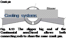 |
Most aviation piston engines are air cooled because in a fixed-wing aircraft a supply of cooling air is easy to come by. This argument is not so powerful in a helicopter in which the relative merits of air and water cooling need to be carefully examined.
Air-cooled engines reach higher peak temperatures and need looser tolerances to prevent seizing. Actually the air-cooled engine obtains a significant amount of cooling from the oil. The oil-cooling system will be heavier in consequence. The cylinders need to be further apart to allow space for the cooling fins needed to increase the surface area of the cylinder and head. This lengthens the engine and makes it heavier.
The in-line configuration is not good for air cooling because the cylinders at the back run hotter and the crankcase is very long. The radial engine is the ultimate air-cooled configuration because all of the cylinders receive equal cooling and the crankcase is short and compact. However, the frontal area and drag are significant. In high performance piston-engine aircraft, such as the Spitfire, the frontal area of the engine had to be reduced as much as possible. This was done using in-line or vee construction that dictated water cooling. In the Spitfire the drag of the radiator and the vee engine together is less than if air cooling was used.
Water has a much higher specific heat than air and so a smaller mass of water can carry away the heat. This means that the cylinders can be closer together because no fins are required. This makes the crankcase shorter and the crankshaft can be lighter. When designed from the outset to be water cooled, an engine with radiator need be no heavier than an air-cooled engine and it will be quieter.
In the helicopter there will be no slipstream in the hover and a cooling fan will be needed whatever the cooling technique. The power loss of an engine-driven fan is considerable, as is the noise it creates and any viable alternative deserves study.
The fuel system of a light helicopter is reasonably simple and the installation used in an Enstrom F28 is shown in Figure 6.14. The object of the fuel system is to ensure a reliable delivery of uncontaminated fuel at consistent pressure to the carburettor or fuel injection system.
The fuel system begins with the tanks. These are invariably installed as a pair, one each side of the mast. The tanks are as close as possible to the CM so that fore-and-aft trim is unaffected as fuel burns off. The two tanks are cross-connected with fuel and
vent pipes so that fuel is used equally from both tanks. This prevents a lateral trim change. As the fuel level is equal in the two tanks, only one fuel level gauge is needed. The transmitter in the tank is connected electrically to the gauge on the instrument panel and so the gauge only works when the master switch is on. It is wise not to place too much trust in float gauges and it is good practice to check the level in the tank itself. Some machines have sight gauges in the walls of the tank. Otherwise a good old-fashioned dipstick can be used.
Mandatory placards are placed near the tank filler caps to indicate the type of fuel to be used. RED for AVGAS, BLACK for AVTUR. It is vital that the correct fuel is loaded. Whilst a turbine will run on AVGAS, a piston engine will stop if AVTUR reaches it. Since AVTUR is denser than AVGAS, it will probably find its way to the engine whilst the machine is still on the ground. A mixture of the two fuels has a very low octane, and the engine could suffer damage from detonation before it stops.
When filling the tanks some consideration should be given to the fact that fuel will expand as the temperature increases. If the machine is to be flown immediately, there is little need for concern, but if the machine is to be left in the sun for any length of time there must be headspace for the fuel to expand into or it may overflow.
The commonest form of fuel contamination is water. Whilst in storage, as a tank is emptied, air fills the space above, bringing moisture with it. Condensation due to low temperatures results in water in the fuel. Condensation can also occur in the helicopter’s own tanks, but this can be minimized by filling the tanks before leaving the machine overnight.
Water does not readily mix with fuel and it is denser, so it will be found at the bottom of tanks. The point where the engine feed is taken from the tank is slightly above the lowest point of the tank so that fuel is drawn from above any water that may settle out in the tank. As a result there will always be a quantity of unusable fuel in the tank, typically about a gallon. The lowest point of the tank is fitted with a drain. This is a spring-loaded valve which is normally closed but which can be pushed open momentarily by hand. Part of the pre-flight check procedure is to operate the tank drains and to catch the fluid that comes out in a transparent container. Any water in the tank will come out first and a clear boundary will be seen in the container between the water and the fuel once all the water has come out.
The tanks are also fitted with air vent plumbing to allow air to enter as fuel is used. In the absence of a vent atmospheric pressure would crush the tanks as the fuel was pumped out. The fuel pickup pipes from the two tanks go to the fuel shut-off valve. This is in the engine compartment, but operated by a rod passing through the firewall to a control often mounted near the pilot’s shoulder. The main fuel line runs down from the fuel shut-off valve through the electric boost pump to the main filter; also known as a strainer. The filter contains a fine mesh element that prevents debris entering the carburettor or fuel injection system where it could block the fine jets. Debris is either trapped in the mesh until it is removed during maintenance, or falls into the bowl. Any water that gets past the measures designed into the tanks will also collect in the bowl. The engine feed is from the top of the filter, so water is left behind. A further vital pre-flight check is to open the spring-loaded drain valve on the filter bowl again catching the results in the glass container. Draining is continued until pure fuel flows. The bowl is then free of water and can trap the maximum amount.
Fuel from the filter passes next to the engine-driven pump. This is mechanical and only works when the engine is running. The combination of electric and mechanical pump one after the other means that fuel pressure is always available even if one of the pumps fails. In addition the electric pump can run without the engine, and this can be useful in fuel-injected machines to purge the injection pipes of fuel vapour prior to a hot start.
The fuel pump contains a pressure regulating mechanism so that constant fuel pressure is available. A pressure switch operates a ‘pressure OK’ light on the instrument panel once fuel pressure exceeds a set threshold. Fuel is then delivered to the carburettor or the fuel injection system.
Figure 6.15 shows the fuel system of the JetRanger. Twin electric boost pumps (1) lift fuel from the tank and check valves (2) allow one to carry on if the other fails. The main fuel valve (7) is remote from the cockpit and is motorized. The airframe filter (8) has a pressure drop monitor (9) that operates a warning light (10) if blockage occurs. The engine-driven pump (15) also has a filter (11) and blockage switch (13). The delivery pressure is regulated in the fuel control unit by returning surplus fuel to the inlet side of the gear pump (16).
In larger helicopters the fuel system will inevitably become more complex. In order to limit the consequences of damage, for structural reasons and to control the CM position, there may be a large number of smaller tanks, each needing provision for refilling, supply and a quantity gauge. A full fuel tank is heavy and may break free in a crash. A deliberately weak point may be introduced in the pipes along with self-sealing valves so that the tank will not leak if it breaks free. Wiring to pumps and gauges will also be designed to detach. In military machines, self-sealing tanks may be fitted. These are essentially double skinned and between the skins is a compound that expands on
contact with fuel. If a tank is pierced, leaking fuel contacts the compound and this will expand, sealing the hole.
Figure 6.16 shows the fuel system of the Chinook. This is complex because there are six tanks, two main engines, an APU and a fuel-burning cabin heater. In addition there is provision for pressure refuelling from a central point as well as connections in the cabin to allow long-range tanks to be carried internally. The fuel is carried in the prominent side sponsons. These cannot contain a single tank for a number of reasons. First, a long single tank would be dangerous because when partially filled all of the fuel could flow to one end and cause a huge trim shift. Second, a single tank would be vulnerable to battle damage. Finally, the front undercarriage leg and its supporting structure occupies some space in the sponson. As a result the Chinook has three tanks along each side. These are not simply interconnected as if one were to be holed this would result in loss of all the fuel on one side. Instead the forward and aft tanks each have a pump which discharges into the main, or centre, tanks. The centre tanks have two pumps in parallel and valves ensure that one can fail without affecting the other.
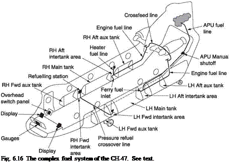 |
Each main tank supplies the engine on the same side, but there is also a cross feed line between the engines so that both can run from one main tank. This line can be closed by the pilot to prevent fuel loss in case of major damage at one side of the machine.
The turbine engine is a more recent development than the piston engine. Although the idea is older than the piston engine, the first aircraft turbines were not perfected until much later when the necessary materials were available. Whittle in England and von Ohain in Germany independently developed practical turbine engines during World War II.
The Otto cycle or four-stroke piston engine draws charge in through a throttle, compresses it, burns it to release power and then exhausts. In the Diesel engine only air is drawn in and compressed, and the fuel is injected directly into the cylinder. There is no throttle, and the power is controlled by the amount of fuel injected. Detonation cannot occur, and low octane fuel can be used. In a piston engine the four phases are conducted sequentially on a fixed quantity of charge in the same cylinder. The turbine is like a continuous version of a Diesel engine. Instead of operating on charge one phase at a time in the same place, charge passes through the machine continuously and the four phases take place at different points in the machine. Like the Diesel, the turbine can use low octane fuel and generally runs on AVTUR which is basically kerosene. Also like the Diesel engine, the power developed by a turbine engine is controlled by the amount of fuel fed to the burners.
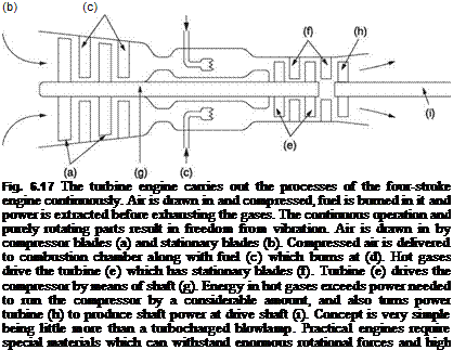 |
Figure 6.17 shows that the turbine engine is effectively a turbocharged blowlamp; in fact simple turbojet engines have been made using turbocharger components. Air is drawn into the compressor: basically a very powerful fan. This compresses the air continuously so that a steady pressure is maintained at the compressor outlet. Compressed air passes to the flame cans or burners where fuel is sprayed in and burned continuously. The charge temperature increases and the gases expand but they cannot overcome the pressure of the compressor and must flow onwards. The expansion results in the gases flowing much faster than the flow rate through the compressor. The hot gas then encounters the power turbine. This converts the energy in the hot gases into shaft power. Some of this is wasted driving the compressor, but the remainder is available to drive an external load.
In the free turbine engine there are two power turbines. One drives the compressor and the other drives the load. Effectively the first turbine and compressor together form a gas generator that powers the free turbine. The gas generator and the free turbine do not generally turn at the same speed. The free turbine should run at constant speed because it is geared to the rotor, whereas the gas generator will turn faster if more drive torque is required. As a result the free turbine engine has two RPMs and these are called N1, the gas generator RPM, and N2, actually the rotor RPM but proportional to the free turbine RPM. In practice, rotor RPM is controlled by adjustment of N1 in order to stabilize N2.
The turbine engine works with steady pressures at each stage and develops continuous power with only low octane fuel, unlike the gasoline engine which needs high octane fuel to prevent detonation and which encounters a serious pressure increase during the power stroke and needs to be strongly constructed to withstand it. The turbine can be much lighter than the piston engine. In turbines, the equivalent of the compression ratio is the pressure ratio: the ratio of compressor outlet pressure to inlet pressure.
Figure 6.18 shows a section through an Allison free turbine engine. Air enters through a multi-stage axial compressor followed by a single-stage centrifugal compressor.
|
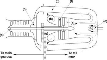
Fig. 6.18 The Allison C-250 light turbine. The compressor has a centrifugal stage and the flow through the power turbine is reversed to shorten the rotating assembly. Compressor is two stage, first stage (a) is axial, second stage (b) is centrifugal. Compressor air is ducted to the rear of the engine by two pipes (c) and led to the burner (d) where fuel is injected. Hot gases drive turbine (e) which powers the compressor, and turbine (f) which is the free power turbine. Power turbine runs on the outside of the mainshaft and transfers power through geartrain (g) to output shaft. Exhausts (h) are at the centre of the engine and lead upwards. Mainshaft has its own geartrain (not shown) to power accessories.
|
The outward flow of compressed air enters two large tubes leading to the burner. The flow is turned around to lead forward prior to entering the burner where fuel is injected. The hot gases then lead forward through the gas generator turbine that drives the compressor and then through the free turbine that powers the helicopter. The exhaust gases are then turned upwards and exit through the top of the engine compartment.
In the centre of the engine are two independent gear trains. One of these transfers power from the power turbine to the rotors and drives the power turbine governor. The other transfers power from the gas generator spool to the fuel pump, the oil pump, the gas producer governor and the hydraulic pump for the powered flying controls. This gear train also allows the electric starter motor to spin the gas producer spool.
A significant advantage of the turbine is that there are no reciprocating parts so that it can turn a lot faster than a piston engine. More charge can be passed at high speed, and more power developed. The output torque is unvarying and allows the transmission to be more lightly built than a piston engine transmission. The power to weight ratio of a turbine engine is quite incredible. In fact a turbine engine has no natural power limit because it has no induction throttle and if not externally controlled by restricting fuel flow could produce so much power that it would reach excessive internal temperatures or RPM and destroy itself. Practical engines are controlled or governed so that they can only produce a fraction of this power so that they will have a reasonable life. An indication of the stress in a turbine engine can be obtained from the turbine outlet temperature (TOT).
When an engine is controlled in this way the power output is said to be flat rated. As power is artificially limited, it can remain constant as the density falls with altitude since this initially limits only the maximum power. Governed power will fall only when the maximum power of which the engine is safely capable falls below the governing threshold. The altitude performance of turbine engines is consequently good. As altitude increases, the reduction in density is beneficially offset by the reduction
in temperature so that mass flow is not reduced as seriously. At high altitude the governor will attempt to maintain power by increasing fuelling. The reduced mass flow reduces the dilution of the combustion products by excess air with the result that the gas temperature entering the power turbine tends to rise. Consequently although the engine could produce power at very high altitudes, in practice power will have to be limited to protect the power turbine. It should be appreciated that the power needed by the airframe may also fall with altitude so this effect is hardly a problem, especially in helicopters.
Power is controlled through limiting fuel admission to the burners. As kerosene in not very volatile it is either atomized at the burner nozzle or heated by passing it through pipes exposed to the burning gases on the way to the burner nozzle. It then vaporizes on leaving the nozzle and burns readily.
Starting a turbine requires an electric motor which will spin the gas generator spool fast enough to make the compressor operate. Once a suitable compressor speed is established (typically 15% of flight idle) the fuel is sprayed through the nozzle and the igniter is operated. This results in hot gas generation that will increase the turbine speed until engine power can take over from the starter motor. The starter motor and igniter are typically turned off at 50% of flight idle. If insufficient compressor speed is achieved before the ignition attempt, combustion pressure will overcome the compressor pressure and the turbine equivalent of a backfire takes place. In some cases the starter motor is permanently connected and becomes a generator when the engine is running.
 |
The job of the compressor is to provide a steady flow of air under pressure to the burners. Compressor design is fraught with compromise primarily because of the need to deliver different flow rates depending on the power required. It is relatively easy to design a compressor that is very efficient under one specific set of conditions, but it may become very inefficient under other conditions. In practice it may be better to design a compressor which is a little less efficient, but which maintains that efficiency over a wide range of flow rates. The compressor can be centrifugal, axial or a combination of the two.
The centrifugal compressor was used in early helicopter turbine engines as it allows a shorter assembly and could be designed using experience from turbochargers. Figure 6.19(a) shows a single-entry centrifugal compressor. The air enters axially near the eye or centre of the impeller at a speed approaching the speed of sound. The blades may be twisted at the eye to allow a smoother entry thus avoiding compressibility effects. As the air moves away from the axis the impeller blades impart higher tangential velocity. In practice the compressor impeller delivers air in a direction having both radial and tangential components. This high velocity is then converted into pressure using an assembly known as a diffuser: basically a divergent duct operating according to Bernouilli’s theorem. The diffuser may at least double the pressure at the impeller outlet and more in some designs.
It is possible to construct a double-entry centrifugal compressor as shown in Figure 6.19(b). This allows twice the mass flow with the same diameter, but is less efficient because the blades run hotter than in the single-entry design which obtains some cooling at the rear of the impeller. A single centrifugal stage may produce a pressure ratio of up to 4.5:1. Stages may be cascaded to produce higher pressure ratios, but then the advantage of shortness is lost. The centrifugal compressor is relatively easy to
make, and is less prone to icing, but is less efficient than the axial compressor which requires more components and may require anti-icing measures. The small area of the inlet eye of the impeller restricts the mass flow unless the overall diameter is made very large. Whilst overall engine diameter is less of a problem in helicopters, the weight of a large centrifugal compressor is unwelcome. Centrifugal compressors are obsolete in main engines, but may be found in APUs.
In the case of an axial compressor, shown in Figure 6.20, the rotor consists of several sets of blades or vanes attached at their inner ends to discs set on a common shaft. Fixed vanes are set between the rotating vanes. The fixed vanes are attached at their outer ends to a stator assembly that is made in two halves so that it can be assembled around the rotor. The fixed vanes act as diffusers for each stage of the rotor to prevent excessive velocity being reached. The fixed vanes also perform a swirl recovery function. It will readily be seen that the axial design allows a large cross-sectional area to be used at the inlet. The mass flow must be the same in each stage, so as the pressure builds up at each stage, the cross-section of the compressor can be reduced. This is done, for example, by increasing the diameter of the mounting discs and by using shorter blades. In order to maintain efficiency over a range of mass flows, the pitch of the first stage of stator vanes may be adjusted by an actuator.
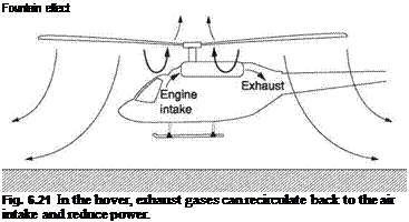 |
Turbine compressors may be affected by a phenomenon known as surge. This is an unstable or oscillating condition that replaces the usual steady-state conditions in the compressor. Surge may be triggered if the airflow into the compressor becomes disturbed. In helicopters the main rotor is very effective at disturbing the air and it is necessary to take some care over the siting and design of the engine intakes. In ground effect, airflow under the main rotor has some toroidal characteristics, including the fountain effect, in which pressure below the rotor leaks through the hub and blade shanks. Figure 6.21 shows that this can draw exhaust gases back into the engine air intakes. Surge may also be initiated during starting if, for some reason, ignition is delayed and a substantial quantity of fuel suddenly ignites.
Surge is characterized by periodic stalling of compressor blades. A stalled blade will reduce the compressor output pressure and combustion pressure may cause reverse flow into the compressor output. This reduction in mass flow through the compressor then causes the compressor pressure to increase, stemming the reverse flow until flow breaks down again. The oscillations due to surge are felt as vibration along with power loss and an increase in TOT as the governor adds fuel in an attempt to maintain power. Surge may be arrested by opening bleed valves in the wall of the compressor stator. These vent pressure to atmosphere and allow the mass flow to increase thereby unstalling the blades.
Compressors work at their highest efficiency when the blades are clean. Over time, the blades get dirty owing to various contaminants, including smog, salt and insects, and efficiency falls. The solution is periodically to wash the compressor. The turbine is motored with the starter motor and water is sprayed into the air intake. The compressor pressure-sensing pipe to the governor must be detached or sealed off during washing to prevent water entering the governor mechanism. The washing procedure may also require the bleed valves to be wedged open.
The turbine is a continuous flow engine and relies on a delicate equilibrium being maintained. There are two related problems to be overcome. The first is that the velocity of flame propagation in kerosene is very slow compared to the air velocity from the compressor, which can be at several hundred feet per second. If directly exposed to compressor flow, the flame would literally be blown out. The second problem is that
|
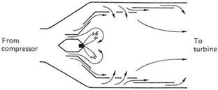
Fig. 6 .22 The combustion chamber diverts a small proportion of the mass flow so that combustion can take place at low airspeed. The burning gases are then recombined with the main flow.
|
kerosine will only burn efficiently at an air/fuel ratio of about 15:1, when temperatures of as high as 2000°C are reached. In practice a range of fuel ratios between 45:1 and 130:1 will be required, and lower temperatures must be arranged at the power turbine to avoid blade damage.
Figure 6.22 shows how the combustion chamber is designed to overcome these problems. Only a small part of the compressor delivery enters the area of the burner, and this restricted flow is slowed down so that combustion can take place. The remainder of the airflow passes around the outside of the burner thereby cooling it. Within the burner, fuel leaves the nozzle in a conical spray and begins to burn with a roughly optimal mixture. The burning gases are joined by the annular airflow from the compressor and the result is that the flame turns inwards and produces a toroidal vortex. Burning fuel can recirculate in the vortex to ensure complete combustion. The high temperatures reached during this process are insulated from the walls of the flame tube by further air from the compressor. As combustion is completed, the hot gases are diluted by further compressor air. As a result the temperature of gases reaching the power turbine is controlled, and a much weaker overall mixture is achieved.
The burner nozzle does a similar job to the carburettor in a piston engine. In order to achieve atomization, the burner nozzle contains a small chamber into which fuel is admitted under pressure by a series of tangential ports. The chamber diameter reduces to the orifice. As the rotating fuel moves to the orifice, the radius of rotation must reduce and conservation of momentum suggests that the rate of rotation must increase. As it emerges from the orifice the fuel is spinning rapidly and is thrown into a cone-shaped spray. The burner has a similar problem to the carburettor when handling the reduced fuel flow needed to sustain idle power. Passing a small fuel flow through a burner intended for full power results in slow rotation, poor atomization and combustion. Figure 6.23 shows that the solution is to build a slow running jet into the nozzle. A nozzle of this kind is called a duplex burner and is controlled by a spring-loaded valve that prevents fuel flowing from the main nozzle until sufficient pressure has been applied to make it work properly.
Several small annular combustion chambers may be arranged around the engine, each fed from the compressor. The combustion chamber outputs are then merged together to drive the power turbine. As an alternative, one large annular combustion chamber may be used. This has several advantages. Flow from the compressor is annular, as is the flow into the power turbine so an annular combustion chamber gives better pressure and flow distribution. The surface area of an annular combustion chamber is also less than that of a multi-chamber system and this reduces losses.
The power turbine is the most highly stressed part of the engine as, like the compressor, it has to operate at high RPM but with the additional problems of working with high temperature gases and at higher power. Turbine inlet temperature may be between 700 and 1200° C. As the temperature is so high, the speed of sound is correspondingly high and gas velocities in the turbine may reach 700 metres per second. The power turbines are almost always axial to provide sufficient flow. Like compressors, power turbines may have cascaded stages with stator vanes between. The power turbine extracts power from the gas flow by reducing its velocity, pressure and temperature. As the gases give up energy, they expand and so the cross-sectional area of the turbine must increase towards the exhaust. As was seen in Chapter 3, a rotor is at its most efficient with uniform inflow. One of the functions of the stator is to modify the radial distribution of gas velocity and pressure so that the gas emerging from the adjacent rotor disc has uniform pressure and velocity from root to tip. The stator vanes also induce swirl in the direction of rotation. The rotor blades are not shaped like conventional airfoils, but have much deeper curvature or camber characteristic of reaction wheels.
One of the greatest challenges in power turbine design is to control the temperature of parts exposed to the hot gas flow. In general oil cooling cannot be applied to the rotating blades because of sealing difficulties and the extremely high oil pressure that would be built up due to the high rotational speed. Thus in practice the parts must be air cooled. Air from the compressor can be used for this purpose. Figure 6.24 shows that the stator vanes are hollow and can be fed with cooling air from both ends. The air can be arranged to exhaust into the gas flow via small drillings in the face of the vane. In this way an insulating boundary layer of air is provided which protects the thin trailing edge of the vane.
The rotor blades are subject to extreme temperatures and extend in length considerably due to expansion. If sufficient tip clearance is provided for expansion, losses due
|
Fig. 6.24 The components of the power turbine are subject to extreme temperatures. The stator vanes are cooled by passing air along them through internal passages. The air may be exhausted to the surface of the vane where it creates a cooler air film over the trailing edge.
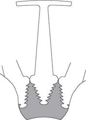
|
Fig. 6.25 The fir-tree method of blade attachment shares the load over a large surface area which also assists cooling.
to gas flow around the tip will be excessive. Rotor blades are generally constructed with an outer ring or shroud to combat tip loss. The blades are cooled by conduction to the hub and shroud and by radial airflow. The hub discs are air cooled to dissipate the conducted heat from the blades.
The blades are rotating at such speed that the root attachment force is of the order of 1000 kilograms. Various means for reliable blade attachment have been developed. Figure 6.25 shows the common method known as a fir-tree attachment. The dimensions
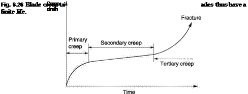
are accurately determined such that when at service speed the strain in the root distributes the thrust over all of the teeth. At rest the blade will be loose in the hub disc.
 |
The rotational stress and temperature experienced by the blade cannot be sustained indefinitely. Under these conditions, all known materials slowly extend or creep. Figure 6.26 shows the creep characteristic of a typical blade. The initial extension or primary creep is rapid, followed by a more stable regime where the secondary creep is relatively slow. At the end of this stage, tertiary creep sets in, leading to failure. There are several consequences of this characteristic. The first is that all turbine engines have a finite service life before the blades need replacing. The second is that considerate piloting that avoids excessive TOT will improve the reliability of the engine. Finally in an emergency it is possible to extract substantially more power from a turbine for a short time than it can reliably sustain. The result will be accelerated creep that will diminish or even use up the service life of the engine, but the helicopter can still fly to safety. This topic will be considered further later in this chapter.
The turbine is mechanically straightforward as there are few moving parts. The rotating parts must be carried on bearings designed to withstand the very high speed. Bearings adjacent to the power turbines must be protected from the enormous temperature of the gases flowing past. This is achieved by oil cooling. Heat flows towards the bearings because of the temperature difference, but the oil carries the heat away at the rate it arrives and so the temperature can be controlled. As there are no heavy reciprocating masses, the major function of the oil is cooling and turbine oil is only about one-tenth the viscosity of piston engine oil so that large volumes can be pumped to transfer heat. The low viscosity oil is also an advantage when starting in extremely cold conditions. An oil cooler is used to transfer the heat from the oil to the surrounding air. In helicopters the oil cooler may be provided with airflow from a transmission-driven fan. The same fan may also cool the transmission oil. Hot oil from the engine may also be used for anti-icing. In some engines, the oil tank forms part of the air intake.
It is vital that the correct shutdown procedure is followed for a turbine engine. The engine must run offload for a time after flight in order to cool down before it is stopped. If this is not done the heat from the power turbines will soak through to the bearings
and carbonize the oil. Synthetic oils have been developed which resist carbonization better than conventional oil. Heat soak may be prevented with an electric pump to keep the oil flowing after shutdown until the hottest engine parts have cooled.
The temperature at the bearings is such that conventional elastomeric oil seals would have a very short life. Instead oil sealing is performed by the use of threaded sections on the shafts that have the effect of screwing the oil back to where it should be. The designer also uses the fact that much of the interior of the engine is at high pressure to keep the oil in place.
Turbine engine power is ultimately controlled by the amount of fuel injected. If the fuel flow is increased gradually, the burner temperature rises and exhaust gases have an increased velocity. This drives the turbine faster and in turn raises PC, the compressor pressure. The greater the pressure between compressor delivery and atmospheric, the more power the turbine can produce.
The air/fuel ratio cannot go outside the limits shown in Figure 6.27 or combustion could cease. If the mixture is too weak the airflow blows the flame away, if it is too rich the cool fuel quenches the combustion, resulting in a flameout. Neither of these extremes is desirable, but can be brought about if the fuel flow fails to match the airflow. This can happen if an attempt is made to change the engine power too rapidly. The accurate fuelling need is provided by a constant-pressure fuel pump feeding a fuel control unit. The fuel pumps are variable displacement devices. Figure 6.28 shows that the pump pistons are driven by a swashplate. When the swashplate is square to the shaft the pistons do not oscillate and there is no flow. As the swashplate is tilted, the pistons create a flow proportional to the tilt. A spring tries to tilt the swashplate to the maximum flow position, but the fuel delivery pressure is applied to a piston opposing the spring. When the fuel flow is low the delivery pressure rises by the small amount necessary to compress the spring and reduce the pump displacement.
The fuel flow control of a turbine engine has to ensure that the fuel flow is always within the limits required for combustion. Power is controlled by slightly disturbing the equilibrium toward one or other of the limits. If it is required to increase power, a slight increase in fuel flow will begin to accelerate the spool, and as it turns faster the
|
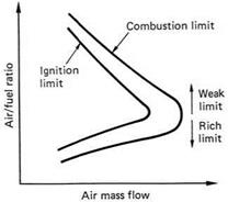
Fig. 6.27 The range of air-to-fuel ratio that allows combustion is quite small for kerosene or AVTUR
|
|
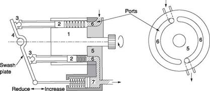
Fig. 6.28 A swashplate pump has variable displacement controlled by the angle of the plate. Rotor 1 is turned by the drive shaft. The rotor contains several pistons 2 which have ball-jointed slippers 3 which slide over the stationary swashplate. This causes the pistons to move in and out of the rotor. The backplate 5 is fitted with ports 6 which allow fuel to enter the cylinders when the piston moves to the left and direct fuel to the pump outlet when the piston moves to the right. The angle of the swashplate determines the stroke of the pistons and the amount of fuel delivered in one rotation. As delivery pressure builds up the piston 7 overcomes spring pressure to reduce the swashplate angle and the pump delivery.
|
fuel flow must increase more rapidly to match the increasing airflow. When the desired power output is reached, the fuel flow is reduced to the new equilibrium level. In order to reduce power, the fuel flow is slightly reduced, and the spool slows down. As it does so, the fuel flow rate must reduce to match the airflow. When the new power level is reached, the fuel flow must be raised slightly to arrest the deceleration.
Figure 6.29 shows how the fuel flow is controlled. Compressor outlet pressure, PC, is delivered to a pair of chambers through small flow restrictor orifices. A large diameter bellows is fitted between the chambers, and a small diameter bellows is fitted between the second chamber and atmosphere. The bellows are joined with a rod that opens the fuel valve as it moves downwards. Air is allowed to spill from the chambers by two valves controlled by the governors. These spill valves are in series with the flow restrictors in the compressor line. An increase in PC collapses the bellows and opens the fuel valve further, admitting more fuel to match the increased airflow. A reduction PC has the opposite effect. The fuel flow is maintained approximately correct by this mechanism. Power output is increased or reduced by disturbing the equilibrium of the bellows system using the spill valves.
If the governor wishes to increase power, it closes the spill valves slightly. This restricts the flow of compressor air and raises the pressure in the bellows chamber, opening the fuel valve. If this is done too rapidly, the mixture will be too rich and the flame will be quenched. This is prevented with the accumulator: a tank preventing the air pressure in the upper bellows chamber changing rapidly. The air has to flow in and out of the accumulator through small orifices and this takes time. As a result when the spill valves are first closed, pressure in the upper bellows chamber rises slowly, and lags behind the pressure rise in the lower chamber.
The pressure difference acts on the upper bellows to oppose the rate of increase of the fuel valve, preventing quenching. As the gas generator accelerates, the accumulator pressure rises and ceases to oppose the increased fuel delivery. Increased compressor pressure due to the higher spool power causes the fuel flow to be further increased. When the governor decides the power has increased enough, it opens the spill valves
once more. The pressure in the bellows chamber falls, but rapid closure of the fuel valve must be prevented or the flame will blow out. This is achieved once again by the pressure lag due to the accumulator.
In some free turbine engines, transient droop is reduced using compressor bleed. If the governor develops a large underspeed error it may operate valves to allow some of the compressor output to leak to atmosphere. This unloads the compressor and allows the spool to accelerate. This technique is used, for example, in the T-55 engines of the Chinook.
The rate of acceleration of a turbine engine is relatively slow and this explains the aircraft carrier pilot’s technique of advancing the throttle to maximum just before touchdown. If the arrester hook fails to catch, the engine will have spooled up to full power in time to go around. If this technique is not used the plane may fall off the front of the ship.
Full Authority Digital Engine Control (FADEC) is a system in which the operation of a turbine engine is completely controlled by a processor. The goal is reduced pilot workload along with greater reliability. With FADEC the engine starting procedure is automated and the pilot only has to turn it on. The stabilization of rotor RPM is
also a FADEC function, along with automatic power balancing in the case of a twin or multiple engine installation. FADEC systems may also be able to handle engine failures by automatically increasing the power of the remaining engine.
Figure 6.30 shows that all of the parameters measured by the instruments and the fuel control, including N1, N2, PC and TOT are converted to digital codes and fed to the processor. This will determine what the fuel flow should be as well as controlling the starter motor, fuel valves and igniters. Needless to say the power supply to the processor becomes critical. The power controller will be wired to multiple sources so that it can run from any one.
Additional feedforward signals may come, for example, from a sensor on the collective lever used by the computer to anticipate a power demand to reduce transient droop. In a conventional governor if the rotor speed goes above normal the engine power will be reduced to contain it. If autorotation is entered, the engine power may be reduced to nearly zero and this will mean that the gas generator spool will be running very slowly. The turbine engine takes considerable time to return to full power from this condition. At the end of the autorotation a conventional governor would not respond until the RRPM had fallen below normal and the result would be droop until the turbine responded. However, in a FADEC machine the computer could anticipate the end of the autorotation by detecting the upward movement of the collective lever and it could start spooling up the gas generator before the RRPM fell below normal. This would reduce the amount of droop.
Sensing the collective lever velocity is also useful in the case of a rejected landing. This is where the machine is landed but the ground is found to be unsuitable. Perhaps the machine has started to break through a crust of ice on top of snow, or the landing area turns out to be waterlogged. Ordinarily the reduction of collective at touchdown would cause a slight overspeed causing the gas generator to spool down. Pulling collective to reject the landing would cause droop. Sensing the collective velocity would help the fuel control anticipate the power requirement.
In twin-engine machines, it is necessary to adjust the fuelling in such a way that the engines share the load. If the FADEC system is sensing TOT and N1, either of these can be used to achieve a load share. In practice, engine tolerances will mean that a balance of TOT may result in a small difference between N1 and vice versa.
Mechanical fuel controls and correlators are complex and expensive and prone to wear. The substitution of stable digital electronics will result in the elimination of wear and allows arbitrarily complex transfer functions to be implemented easily. However, the downside of FADEC is that it requires the control software to be utterly reliable. The difficulty with computers is that the number of states and combinations that can be achieved is staggering and it is therefore very difficult to prove that the computer can correctly recover from every possible state. In the development of FADEC systems there have been some spectacular failures, including an in-flight rotor speed runaway on a Chinook that required the pilot to climb at record speed to prevent the rotors being thrown off until the engines could be shut down.
In well-engineered systems a FADEC failure should leave the pilot, or co-pilot, with some form of manual power control, even if RRPM is not as precise.
 |
As there is no throttle an inlet pressure gauge would be pointless. The actual power being generated is a fairly stable function of the reading displayed on the fuel flowmeter so this or the torque meter may be used for power checks. An intake air temperature indicator will be provided so that the pilot will have an indication of the maximum power available. N2 (power turbine RPM) is proportional to RRPM and needs no separate indication. However, N1 (gas generator RPM) will have its own tachometer. The power turbine inlet temperature (PTIT) is measured by thermocouple in the engine and displayed on the instrument panel and will be red-lined at a safe temperature above which the turbine blades may be damaged. In some cases the turbine outlet temperature may be measured instead. This is simply because the temperature is lower at the outlet and the sensors may be less expensive. In the case of an engine failure, the remaining engine may run at higher power and this will cause PTIT/PTOT to exceed the red line and enter the contingency power range. This will result in a caution light illuminating. Usually a timer also runs to assess the stress caused to the engine. The oil pressure and temperature are displayed as for the piston engine. Oil quantity may also be displayed. There may also be chip detectors in the oil system.
 |
When refuelling, whoever actually undertakes the task, the responsibility is taken by the commander of the machine. It is essential to specify the quantity and type of fuel required and to check that this has actually been supplied. AVTUR and AVGAS smell
quite different and the nose will quickly establish that the correct fuel has been loaded. Gasoline engines will not run on AVTUR, whereas turbine engines will burn almost anything. For low temperature operation turbines may be run on a mixture of one part lead-free AVGAS and two parts AVTUR.
In addition to AVTUR and AVGAS there are MOGAS and ordinary car fuel. Car fuel is made to fairly slack specifications and no warranty of freedom from contamination is given with it. The composition of car fuel may vary with the season. In winter it may have higher volatility than AVGAS and can cause vapour locks in the fuel pipes. It should never be used for any aviation purpose. MOGAS is made to tighter specifications than car fuel and may be suitable for some aircraft piston engines but should not be used without a specific check.
When refuelling from drums, it must be borne in mind that the drums could have been in storage for some time. There will be an expiry date on the label. There could be rust or other dirt in the fuel along with water. If this is suspected, fuel should be taken on through a filter to remove debris, and through a chamois or felt pad to soak up water. After fuelling, the tank and filter drains must be checked for water before flying. In the event of heavy water contamination, the tanks may have to be drained and refilled.
If it is proposed to load only sufficient fuel to make a given flight, perhaps in order to increase payload, an allowance must be made for headwinds along with half an hour for contingencies. The flight time plus allowances must be multiplied by the machine’s hourly consumption figure for the planned load. It is important to be quite sure of the units in use. Unfortunately fuel can be measured in pounds, kilograms, imperial gallons, US gallons and litres and there have been forced landings where the refueller assumed a different unit from the captain. In such chaos, the old-fashioned dipstick makes an excellent safety check. However, tanks are often an irregular shape and the quantity is not always proportional to the depth of fuel.
 |
In the pure helicopter, the rotor provides all lift and propulsion. The rotor is an actuator converting shaft power into thrust. The primary functions of the transmission are to deliver the shaft power and to transmit the thrust to the hull. Secondary functions of the transmission include driving the tail rotor and vital services such as hydraulic pumps and generators. There must be an autorotation clutch that allows a failed engine to stop whilst the rotors carry on turning. In some machines the transmission also drives cooling fans. There may also be a rotor brake to stop the rotor quickly after landing. In piston-engine machines a clutch will generally be needed to allow engine starting. Free turbine engines have no need for such clutches, but in twin-engine machines having no APU, an extra clutch may be fitted to allow one engine to be run without the rotors turning.
Figure 6.31 shows the construction of an autorotation clutch. There are two coaxial races that are cylindrical. The outside member is typically engine driven whereas the inner is attached to the transmission. Dog bone-shaped wedges known as sprags are positioned between the inner and outer races. The sprags are located with a pressed steel cage. The sprags are slightly asymmetrical. As the figure shows, if a sprag turns one way, its effective thickness increases, whereas if it turns the other way the thickness reduces. The sprags are biased in the former direction with light springs. If the outer race turns one way, the sprags are twisted against the springs and slip so that no drive is transmitted. If the outer race turns the other way, the sprags are twisted in such a way
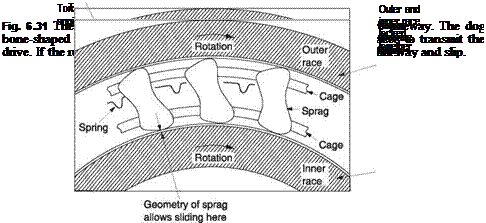 |
that they expand to fill the space between the races that are thus locked together. The more torque that is applied the harder the sprags grip. If the engine stops, the inner member runs on, releasing the wedging force so that it is free to turn. The action of the autorotation clutch is fully automatic and needs no control. It should, however, be checked for correct operation before flight. With the rotor at flight RPM, the throttle is briefly closed to prove that the engine can slow down whilst the rotor runs on.
The main rotor of a light helicopter needs to turn at something like 300 RPM which is rather slower than the piston engine which runs at more like 3000 RPM, so the transmission performs a speed reduction. The turbine engine runs much faster than the piston engine and the reduction ratio to the main rotor shaft will be of the order of 100 : 1. In a large helicopter the disparity between rotor and engine RPM will be higher. The continuous rotary power generated by the turbine is free of the torque impulses of the piston engine and the transmission can be lighter. The tail rotor usually has a similar tip speed to the main rotor and so needs to run at an RPM between those of the engine and the main rotor. In a light helicopter, the transmission may incorporate
two reduction stages as was shown in Figure 6.1. The first will reduce engine RPM to approximately tail rotor RPM, and the second will reduce the tail rotor RPM to main rotor RPM. The tail rotor gearbox contains a pair of bevel gears to turn the drive through a right angle. This has usually a near 1:1 ratio, but some variation is possible. In development the tail rotor RPM may need to be changed to obtain a different compromise between noise and available thrust, or if the solidity is changed. This can be achieved by changing the tail gearbox ratio. In machines with cranked tails a further gearbox may be needed to turn the drive at the base of the fin.
Although simple at one level, gearboxes incorporate some subtle detailing. Consider a gearbox with a ratio of 2: 1. The gears have, for example, 40 and 20 teeth. As these numbers factorize, each tooth on the small gear only touches two teeth on the large gear and any irregularities would form a wear pattern. However, if the number of teeth were to be relatively prime, every tooth would touch every other tooth and this would result in the irregularities averaging out. This could be achieved by using 20 and 41 teeth. For this reason gearboxes seldom have simple ratios.
If the gear teeth were parallel to the shafts, the gearbox would make a lot of noise and vibration as the drive jumps from one pair of teeth to the next. In practice the teeth are twisted so that the point of contact slides along the shaft as the gears rotate. Contact between the next pair of teeth begins just before the current pair part company and the result is a more even power transmission and less noise and wear. Helical gears produce end thrust on the shafts because of the angular contact. The angled contact faces of the gear teeth also cause the shafts to be forced apart. The gear case, the shafts and the bearings must be stiff enough to contain the forces generated without distorting. Distortion will reduce the accuracy of tooth mesh and destroy the uniformity of the tooth loading. Tapered roller bearings resist combinations of radial and axial forces. When used in opposed pairs, the outer race of one of the bearings can be adjusted axially to remove all play in the shaft and apply a slight pre-load to the rollers to stop them skidding.
Figure 6.32 shows that in most gear systems both gearwheels have convex teeth making the contact patch between the teeth very small. In conformal gearing, one of the gearwheels has concave teeth designed to rotate around the convex teeth of the other gear. This allows a much larger contact area so that a given size of gear can transmit more torque. The Westland Lynx has conformal gearing.
The epicyclic or planetary reduction gearbox is popular in helicopters because it can be built with low weight for the torque handled. Figure 6.2(a) showed that there is a fixed internally toothed gear which is coaxial with the input or sun gear. Between these gears are three planet gears that are fitted to pins on the output shaft. As the sun gear rotates, the planets orbit the ring gear and revolve at the same time. The part of the planet gear in contact with the sun gear is travelling twice as fast as the axis of the planet gear. As a result the planetary mechanism itself gives a 2:1 speed reduction which may further be increased by reducing the size of the sun gear. The torque is shared between the three planets and applied at three different places on the sun gear and the ring gear. This makes the epicyclic gearbox ideal for the final stage of rotor drive where the torque is greatest. Figure 6.33 shows a Chinook gearbox, in which the final stage epicyclic gear ring can be seen.
The gear teeth slide over each other, and metal-to-metal contact is prevented by special gear oil known as extreme pressure (EP) oil. The viscosity of the oil means that it is not squeezed out from between the teeth by the contact pressure. The sliding then takes place in the shearing of the oil film. Shearing viscous oil produces heat and the gearbox casing may be made with fins to dissipate the heat. In large machines an oil cooler may be fitted, perhaps with a fan and oil pump. In some machines the oil
|
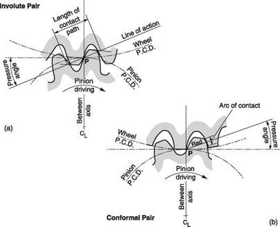
Fig. 6.32 At (a) the conventional gear tooth is convex and has a small contact patch. At (b) the conformal gear has one wheel with concave teeth and one with convex teeth. This increases contact area and reduces the distortion of the tooth allowing higher loading.
|
|
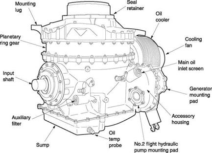
Fig. 6 .33 The epicyclic or planetary gearbox of a Chinook, showing the outer ring gear.
|
tank forms part of the engine air intake so that de-icing is available with no additional power required. The gearbox usually has a temperature probe which drives a gauge in the cockpit. It is absolutely vital that the main gearbox is filled with the right kind of oil. EP oil generally has a sickly smell of almonds.
The gearbox will be fitted with a sight glass so that the oil level can be seen from the outside. Some machines have a chip detector. This consists of a pair of electric contacts that are also magnetic. These are situated at the bottom of the gearbox. If a gear loses part of a tooth, or a bearing starts to break up, the debris will be attracted by the magnet and will bridge the contacts, turning on a warning light in the cockpit. Some machines may also be designed so that the transmission can continue to function for a short period even if all of the oil is lost.
As a helicopter rotor gets larger, it will turn at lower RPM as the tip speed tends to remain fixed. The larger rotor will need more power but at a lower RPM. Thus the torque delivered by the gearbox increases disproportionately with size, and may limit the maximum size of conventional helicopters. The twin-rotor helicopter has an advantage which is that for a given disc area the rotor radii will be smaller and the RRPM higher. This reduces the torque needed and the numerical gear ratio, both of which lighten the gearboxes to the extent that the two gearboxes may be lighter than the single gearbox in a conventional machine of the same weight.
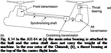 |
Rotor forces must be carried into the hull by a suitably reliable thrust bearing. In many helicopters, the main rotor is fitted directly to the transmission output shaft so that the rotor thrust is carried by the transmission bearings and the gear case. As an alternative, the rotor is carried on a bearing attached to the hull structure. In this case the transmission only provides drive torque and the drive shaft is freed from flight loads. It is advantageous to transfer rotor forces into the hull as directly as possible. An offset CM causes alternating bending loads in the shaft but constant loads in the hull. A further advantage of the use of a separate thrust bearing is that the transmission can be replaced without removing the rotor. Figure 6.34(a) shows the arrangement of
the AH-64 Apache. In the Chinook, shown in Figure 6.34(b), the front rotor thrust is carried by the transmission, whereas the rear rotor has a thrust bearing at the top of the fin. The drive shaft is fitted with a splined coupling so that hull flexing does not stress the transmission.
There are a number of reasons for installing more than one engine in a helicopter. One obvious result is increased power, but clearly this is only obtained if all the engines are working. Another reason may be to increase safety. If one engine fails, the other(s) will continue to provide some power. Another possibility is to improve range or economy by shutting down one engine in cruise.
In a multi-engine helicopter, each engine will have its own one-way clutch so that the loss or seizure of one engine does not prevent the transmission turning. In most cases twin engines are fitted for safety reasons. Single engine helicopters are not permitted to fly over built-up areas. Ideally in the case of an engine failure the machine would be able to continue normal flight. However, this would mean that each engine would have to deliver the same power as a single engine. In the case of turbine engines this is very inefficient because in normal flight both engines would be delivering only half their rated power. However, the power needed to drive the compressors would be twice the case for a single engine and this would impair the fuel consumption.
In practice a helicopter only needs full power for a short time, typically at take-off with a full fuel load and landing at a hot/high destination. For the rest of the flight less power would be acceptable after a failure by using lower speeds and reduced rates of climb. Turbine engines are very reliable and failures are relatively uncommon. Consequently instead of overengining a helicopter, it is more sensible to design engines that can be overrated for short periods of time. Thus in addition to the continuous power rating an engine would have a higher ‘contingency’ rating which it could only tolerate for a few minutes. There may also be an even higher emergency rating that might only be sustainable for half a minute. If an engine enters one of these conditions, an indicator operates which can only be reset on the ground and a timer runs to measure the degree of overload.
The use of these contingency power ratings in some cases may put the engine under such stress that it will need immediate overhaul, but the frequency with which this happens is so low that the saving in fuel when the engines are working normally is of more consequence.
Figure 6.35 shows how a twin-engine helicopter might take-off from a rooftop helipad in a built-up area. The take-off is conducted upwards and backwards at first so that the helipad remains in the pilot’s view. If, during this initial climb, an engine fails the pilot has the option of returning to the pad and the time for which contingency power is needed would be quite short. The height reached in the initial climb has to be such that if an engine failed just as the machine moved into forward flight it could use the power of the remaining engine and the power obtained by losing height to reach minimum power speed without falling below the height of the pad or nearby buildings.
If another engine of the same type is fitted to a single engine helicopter, the safety aspect will be improved, but the fuel economy will suffer because the losses of two compressors are being borne. At a sufficient height, one engine could be shut down so that the other runs more efficiently. In the event that the running engine fails, provided the second engine can be started promptly, flight could continue to a convenient point.
Clearly before descending below a certain height the second engine would have to be started. The certification process would have to include determination of the critical height and the demonstration of reliable restarts.
One important point is that the redundancy of twin engines is only achieved if they are independent in every respect so that no single failure could stop both. Whilst an engine might fail because of a non-violent problem such as a broken compressor pressuresensing pipe, it should be borne in mind that turbine engines also fail violently through blade disintegration on occasions. If debris from a failed engine can damage the other engine then it too might fail. In a civil helicopter it would be adequate to have a barrier between the engines or engines designed to contain shed blades. In a military machine, the engines may also expect damage by enemy fire and in this case a significant physical separation is required so that an explosive loss of one engine does not affect the other. The pod-mounted engines of the Apache and the Chinook are good examples of this philosophy.
Figure 6.36 shows the transmission of the Westland Sea King. This twin-engine machine has hydraulically folded blades but no APU. There is one overrun clutch for each engine, but one engine has an extra clutch allowing it to be started and run with the blades folded so that accessory power is available. The accessories are driven through one-way clutches from one engine and from the main transmission. With the first engine running, hydraulic power is available to unfold the blades. The second engine is then started and used to bring the rotors up to speed. When this has been done, the clutch of the first engine can be engaged so that both engines can drive the transmission.
A light helicopter may have no transmission instruments at all and ensuring the correct oil level is all that can be done. In most piston-engine machines, the transmission can withstand more torque than the engine can deliver and so it is difficult to overstress the
transmission. As helicopters get larger, the transmission becomes more complex and under more stress and instruments become necessary.
The turbine has vast power reserves and a speed governor. If the pilot applies a large amount of collective pitch during a high inflow condition, the induced drag on the rotor will be at its greatest. This would tend to slow down the rotor and thus the free turbine, but the governor responds by increasing fuel flow so in fact the result is an increase in engine torque not a reduction in RRPM. This is fine for the rotors but it is less so for the gearbox where a torque overload could distort the casing and misalign the gears or break through the oil film separating the gear teeth. To help prevent this, turbine helicopters are fitted with torque meters to display the gearbox torque on the instrument panel. The gauge will be red-lined at the safe limit for the gearbox and the pilot then should limit the severity of manoeuvres to stay within the torque limit. Helicopters with hingeless rotors may also be fitted with instruments to display the bending stress in the mast due to the application of cyclic control.
The heat dissipated in the gearbox will be roughly proportional to the torque and so a transmission oil temperature gauge would tend to reflect the torque meter history. An excessive transmission oil temperature is the cause for concern because this may permit metal-to-metal contact with serious consequences. If the high temperature is due to known heavy use, the machine must be flown at reduced power to contain the temperature. If the high temperature cannot be accounted for in this way, then there is a possibility of a problem such as oil loss, a blocked cooler or loss of airflow through the cooler and investigation will be necessary.
Gearboxes are commonly fitted with a chip detector. This is a plug fitted in the oil sump carrying insulated magnetic electrodes. In the event of any ferrous debris finding its way into the oil, the magnetic electrodes will attract it and the debris will bridge the electrodes, completing a circuit and lighting an indicator.
There are two basic types of torque meter. In the first type, engine torque twists a slim shaft in the drive train, and the amount of twist is measured with a set of strain gauges. These are fine metal wires embedded in an insulating material. Four such strain gauges
are mounted in a diamond-shaped pattern on the shaft and connected electrically as a bridge. Power is applied to the ends of the bridge and the outputs are taken from the centre to a differential amplifier. As the shaft temperature increases, all of the strain gauges will increase in length but this will have no effect on the differential signal as all four gauges are equally affected. However, if the shaft is twisted, two of the gauges will contract and two will extend, producing a differential signal. The power and signals are communicated using rotary transformers.
In the second, the end thrust on one of a pair of skew gears is measured. One of the shafts is allowed to move axially. As it does so it reduces the area of a port that allows oil to escape from a chamber at the end of the shaft. The oil is supplied under pressure from the engine oil pump, through a restrictor. Engine torque will slide the shaft into the chamber until the restriction of flow causes the oil pressure to rise and oppose any further motion. The oil pressure is now proportional to the torque and can be displayed on a gauge.
The rotor RPM must be maintained at the correct setting during all modes of flight since the response to the controls and the available lift are both affected by it. Low rotor RPM makes the controls sluggish and reduces tail rotor authority. Vibration control techniques employing tuning only operate at one RRPM.
The rotor rev counter is one of the most vital instruments in the helicopter. It is generally concentric with the engine rev counter. Each instrument is independent and has its own scale and needle, but the scales are graduated so that when the engine is driving the rotors the two needles overlap and move together. In a piston engine machine, the engine rev counter is crankshaft driven, whereas in a turbine engine the RPM of the power turbine (N2) is measured. The rotor rev counter is driven by the transmission after the autorotation clutch.
Figure 6.37 shows some typical displays. At (a) both engine and rotors are stopped. At (b) the clutch is disengaged, and the engine has been started and is warming up. At
(c) the engine is warm and the pilot is starting to engage the clutch. At (d) the clutch is fully engaged. The needles are said to be married. At (e) the pilot has advanced the throttle to flight RPM with collective fully down. At (f) the throttle is closed from flight RPM and the rotors continue turning whilst the engine slows down. This action tests the autorotation clutch. At (g) the machine is in normal flight. At (h) the pilot has let the revs drop and the bleeper has sounded. At (i) the pilot has initiated a practice autorotation. The engine has dropped to idle, but the rotors maintain flight RPM. This is called ‘splitting the needles’. At (j) the machine flares in autorotation. Rotor revs have gone up to maximum permissible. If the pilot wishes to abort the auto and resume powered flight, he must not advance the throttle at this stage, because the high rotor revs will allow the engine to overspeed. The correct procedure is to reduce the rotor revs first, and then to bring the engine revs up slowly so that the needles meet at flight RPM as shown at (k). At (l) is shown the result of an engine failure. The engine has stopped and the rotors are slowing down. It is necessary to enter autorotation. Since the rotors are turning at normal speed, an in-flight restart does not require the clutch to be disengaged. Not shown is a condition resulting from transmission failure between the engine and gearbox. The rotor slows down and the engine may overspeed as the correlator attempts to maintain RRPM. It will be necessary to enter autorotation and shut off the engine.
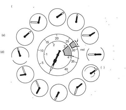 (a) Engine and rotors

stopped
Fig. 6.37 Displays which may be seen on a coaxial helicopter tachometer. See text for details.
The use of thrust directly applied at the blade tips has an obvious appeal to designers because the conventional transmission is eliminated along with its weight and torque reaction. The tips of a helicopter blade move at a high subsonic speed and jet thrust matches this kind of application well. Despite those advantages, the use of tip jets remains uncommon because they introduce other problems instead.
Figure 6.38 introduces the various options available for tip jet drive. At (a) is the tip-mounted rocket in which fuel and oxidant are supplied along the blade. These react in the rocket motor to produce a vast increase in volume. At (b) is the ramjet and its cousin the pulse jet which take in air locally so that only fuel needs to be supplied along the blade. The tip-mounted turbojet is in the same category. At (c) is the pressure jet system in which compressed air produced in the hull is ejected at the blade tips. This is known as a cold-cycle system. At (d) in the tip-burning system fuel is piped down the blade and burned in the compressed air supply to produce greater thrust. At (e) the exhaust of a turbine engine is piped down the blades. This is a hot-cycle system.
Figure 6.39(a) shows that the ramjet or athodyd (aerothermodynamic duct) is a simple device in which air entering at the front is compressed by virtue of the forward motion through the air. This dynamic pressure is enough to overcome the pressure due to combustion so that exhaust gases are ejected from the rear to produce thrust.
Fig. 6 .38 Various options for tip jet propulsion. All of these eliminate torque reaction. At (a) the tip rocket is fed with fuel and oxidant down the blade. At (b) the ramjet, pulse jet and turbojet all take in air and only need a fuel supply. At (c) the cold-cycle pressure jet system pipes compressed air to the blade tip. At (d) the tip-burning system. At (e) the hot-cycle system feeds turbine exhaust down the blade.
The ramjet is not self-starting and in a helicopter application the rotors must be brought to an appreciable tip speed before the ramjets can be started. This might require an electric motor or an auxiliary piston engine. The McDonnell Little Henry experimental helicopter used ramjets, as did Stanley Hiller’s Hornet.
Figure 6.39(b) shows that the pulse jet is an intermittent combustion device. Forward motion or a supply of compressed air is needed to start. Air enters the combustion chamber through a flap or reed valve and is mixed with fuel and ignited. The pressure increase shuts the reed valve which causes the combustion products to be ejected rearwards, producing thrust. However, when the thrust cycle is over, the momentum of the exhaust gases in the tailpipe causes a pressure drop in the combustion chamber. This causes the reed valve to open, admitting more air for the next cycle. An engine of this type was used in the Fieseler Fi-103 flying bomb of World War II; an early cruise missile aka the V-1.
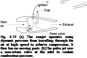 |
 |
Hiller buried the mechanism of a pulse jet inside the length of a rotor blade with the fuel inlet and valves at the hub and an angled nozzle at the tip. This was known as a powerblade. Hiller also developed valveless pulse jets in which the gases in the engines resonated like organ pipes. This overcame the tendency of the valves to malfunction because of the high-g environment. Needless to say pulse jets and sonic engines also produce phenomenally high sound levels that preclude their use today.
In the pressure jet system the hull contains an air compressor. This may be driven by piston engine, or it may be the compressor stage of a modified turbine engine. The compressed air is fed through a rotating seal into the rotor and ejected rearwards at the tips. This makes much less noise than tip-burning or tip-mounted motors. The French SNCASO Djinn used this system and reached production.
An alternative approach to pressure jet drive is to obtain the jet pressure chemically. Machines have been built which are propelled by the catalytic decomposition of hydrogen peroxide. If liquid hydrogen peroxide is passed over a catalyst such as calcium permanganate or potassium chromate, it spontaneously decomposes into steam and free oxygen. The noise level of a rotor driven in this way is very low, but the running cost is fantastic and hydrogen peroxide is corrosive and prone to explode if impurities are present.
The Doblhoff tip-burning helicopter used a piston engine in the hull driving a supercharger to provide compressed air for the tip motors. Rotor power was only used for hovering. Once forward flight was established, the machine was driven by a conventional propeller and the rotor would windmill like an autogyro. Doblhoff’s machine mixed the fuel with the air before it entered the blades. Whilst this eliminated the need for fuel piping in the blades, it meant that each blade was full of potentially explosive mixture. In the Hughes XH-17 flying crane the safer route was taken and fuel was piped to the tip burners.
The tip jet helicopter has not achieved wide use for a number of reasons. One of the most serious of these is noise. The pulse and ramjet are never going to be silenced, especially as allowable noise levels are falling. Pulse and ramjets are not fuel efficient at
the speeds of helicopter blades, as they cannot reach a high enough compression ratio with only dynamic pressure at the intake. Their fuel consumption is about ten times that of conventional engines, which outweighs the fact that they will burn almost anything.
Hiller’s powerblade was an unsolvable compromise because low drag required a slim blade section too small to contain an efficient engine. The additional constraints of the hot-cycle approach make blade design harder because the blades have to withstand high temperatures as well as flight loads. Tip-mounted motors such as pulse and ramjets create enormous drag when the motor stops. This makes the rate of descent in autorotation rather too fast for comfort and as a result no machine of this type was ever certified.
Pressure jet rotors don’t have a serious noise problem and their autorotation performance isn’t impaired. However, the frictional losses of ducting the air to the blade tip are serious, with the result that the overall gain when compared to a conventional transmission is small. Finally, although there is no torque reaction, tip jet helicopters may need a tail rotor in order to meet crosswind hover requirements.
Hiller has correctly pointed out that in order to construct a very large helicopter, with a rotor diameter measured in hundreds of feet, the transmission weight would be intolerable with a conventional design. Instead Hiller proposed the installation of turbojet engines at the blade tips. With large, very slow turning rotors, the g force at the blade tips would not be serious and a turbojet engine would work well there.
The electrical system is needed for engine starting, lighting, instrument power and to operate the avionics. When the engine is running, electrical power comes from the alternator. When the engine is stopped, the battery will be used. Most light helicopters use a nominal 12 volt battery which is constructed from six 2 volt lead-acid cells in series. Some machines have nickel-cadmium batteries and these will use ten 1.2 volt cells in series. Late Enstroms and JetRangers have 24 volt systems.
A lead-acid battery only has a terminal voltage of 12 volts when it is supplying a light load. In order to charge the battery, the terminal voltage must be raised to about 14.4 volts. Current will flow into the battery instead of out of it, and it will recharge. Conveniently the battery voltage rises slightly as recharging is completed, reducing the charging current automatically. If the applied voltage is maintained constant, the battery will take current until it is recharged, when the current will fall to a trickle. A lead-acid battery evolves hydrogen and oxygen when it is recharging, and provision must be made to vent these gases to avoid explosion risk. In the Enstrom the battery is beneath the starboard seat in the cockpit. Charging a flat battery in the machine is forbidden since it could fill the cockpit with an explosive mixture. The level of the electrolyte must be checked periodically.
A nickel-cadmium battery has different charging characteristics. When it is fully charged, the voltage does not rise very much, and charging current continues to flow. This current is converted to heat instead of charge. The battery temperature is sensed and displayed on the instrument panel. If the battery temperature reaches an excessive value, the alternator is switched off until some cooling takes place. An advantage of Ni-Cd batteries is that they do not outgas or need topping up.
The regulator controls the system voltage when the engine is running and the alternator is switched on. This may be a separate unit or integral with the alternator. An alternator (Figure 6.40) consists of a rotor (3), driven by the engine, which can be magnetized by direct current flowing through a coil. This field current is fed in through
sliprings (2) and carbon brushes. The rotation of the resultant magnetic field causes flux reversals in the stationary magnetic circuit or stator surrounding the rotor. A winding (4) on the stator will produce an alternating voltage. This cannot be used directly in a system using a DC battery, but must be rectified using diodes (5). Clearly rectified alternating current is very irregular, and in practice a more constant current is obtained by mounting three sets of coils on the stator at 120°. This results in a three-phase alternator and if the output is rectified with six diodes as shown in Figure 6.40 the voltage is much more constant. The diodes are usually incorporated into the alternator body so that they may be cooled by fan.
The output voltage is proportional to the field current. The voltage regulator (1) senses the system voltage, and if it is excessive, the field current is reduced. If it is too small, the field current is increased. As a result the system voltage will stabilize at a fixed value even if different loads are switched on and off. A voltage regulator failure could result in full field current being applied. In this case the alternator output current would be limited by the inductance of the windings. The battery would absorb much of this current and eventually boil dry. Some machines have an overvoltage sensor to cut out the alternator if this happens.
|
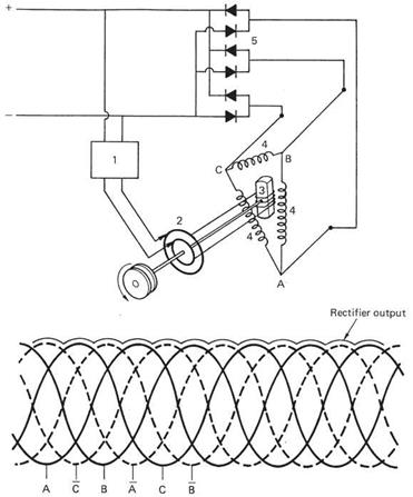
Fig. 6.40 The alternator of a light helicopter is fitted with a three-phase rectifier to provide DC power.
|

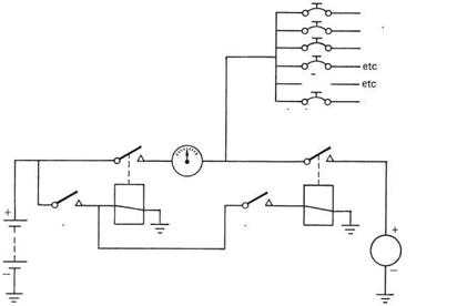 Alternator
Fig. 6.41 Electrical system of a light helicopter showing the position of the ammeter and the master switch.
The state of the battery and alternator can be assessed using an Ampere meter, always abbreviated to ammeter, which is connected as shown in Figure 6.41. When the engine is stopped, electrical loads are supplied by battery, and current flows out through the ammeter which will register discharge (—). When the engine is started, the battery will have been partially discharged by the starter motor, and current will flow back from the alternator to charge the battery, registering charge (+). As the battery becomes recharged the magnitude of the charging current will fall and the ammeter will return to the null position where it will remain. If the ammeter displays a discharge with flight RPM, the alternator is not supplying enough current, it is switched off or some load has been applied beyond its capacity. A common explanation is that the belt driving the alternator has broken or is slipping.
Figure 6.41 also shows that the master switch isolates all electrical devices from the battery (except the clock). In some cases the total electrical load is too large for a switch and a relay or contactor is used. This is a small version of the starter motor solenoid and is controlled by a small current from the switch itself. Generally only one wire feeds current to each device and current returns through the metal frame of the machine.
If a failure of the insulation occurs somewhere in the electrical wiring, current could flow direct to the frame with little resistance to stop it. The high fault current could cause a fire in the wiring. This is prevented by splitting the wiring into sections and protecting each with a fuse or circuit breaker. In the case of a fault, the section containing the fault will carry an excessive current that melts the fuse or magnetically trips the breaker. The current is cut off and the fire is prevented. Equally importantly, the supply is maintained to all other sections; only devices using current from the affected section will lose power.
A fuse is cheap and effective, but it has to be replaced if it fails. A fuse should only be replaced with one of the same rating. If a fuse is replaced with one of a higher rating, the protection it gives is lost and the wiring could burn in the case of a fault. A circuit breaker pops out when tripped and can be reset by finger pressure. In addition breakers can be used as switches by pulling them out. A tripped breaker does not always indicate
a fault. Some loads, particularly electric motors and electronic equipment, draw a surge current when first switched on which is higher than their running current. If the surge current is close to the trip current, once in a while the breaker will trip when a particular load is applied. The breaker can simply be reset, and if all is well it will not trip. If there is a genuine fault, the breaker will refuse to reset and it should be left tripped and the cause investigated. If a breaker trips in flight, the appropriate action depends on how necessary that circuit is. Loss of the engine instrument power calls for a landing at the next airfield for repairs, whereas loss of the landing light on a summer morning is less urgent. Nevertheless all electrical problems should be treated with the utmost suspicion in case the apparent fault is a symptom of something else. The ammeter is a good friend at times like these. If the ammeter is showing a null reading, a heavy fault current cannot be flowing and there is unlikely to be a fire risk.
Some machines have provision for a ground power source to be used. This would ease the load on the battery when starting in extreme cold, for example. It is important that the ground power unit is compatible. Some aircraft use 24 volt DC electrical systems, and if a 24 volt ground supply is plugged into a 12 volt machine extensive damage will result.
In larger machines, AC power systems are used. These will operate at 400 Hz rather than the 50 or 60 Hz land-based power because the mass of components can be reduced as the frequency rises. Alternators may be driven from the engines or the transmission. As the alternator output frequency is proportional to shaft RPM, system frequency will vary with RRPM. Alternators will usually disconnect themselves if the shaft speed falls below about 85% of nominal.
As helicopters become larger, heavier and faster, the forces necessary to control the rotor head become too great for the pilot to manage reasonably, and some form of power operation is necessary. If stability augmentation or autopilot functions are required, powered controls will also be needed so that the control information can fly the machine.
Control forces may come from a variety of sources. The advancing blade may bend back putting a significant area at some distance from the feathering axis. This will feed feathering loads back into the swashplate. The advancing blade tip can enter the region of compressibility and this may also result in a pitching load. It was shown in Chapter 3 that rotor blades tend to return to flat pitch and a significant thrust is needed in the control system to obtain positive collective pitch. The enormous tensile forces in the blade root require adequately strong feathering hinges. These inevitably must be stiff to move. In larger helicopters, power operation will be required beyond the flying controls. Winches, cargo doors and ramps, underslung load release, wheel brakes and steering may all be powered.
There are two basic types of hydraulic systems: fully powered and power assisted. In large helicopters the controls are fully powered. The consequences of control loss are serious and real systems have to be designed so that failure of any one part (and often more) still leaves at least some measure of control. Many systems have a completely duplicated hydraulic system powered by two pumps driven independently from the transmission. Whatever happens to one hydraulic system, the other should remain functional. In addition hydraulic systems may be interconnected by motor/pump combinations known as power transfer units. In the case of a main pump failure, the power transfer unit driven by the remaining system can pressurize the failed system.
In smaller helicopters the controls are power assisted and in the event of hydraulic failure the pilot can still operate the controls, albeit with greater effort. The JetRanger, for example, uses a single power assisted control system and can be flown without it, whereas the CH-47 has duplicated fully powered controls. This section first considers hydraulic power principles and uses the machines mentioned as examples of actual practice.
There are many ways of obtaining power operation, but the high pressure hydraulic system has the advantage that large forces can be developed in compact actuators. The linear action of hydraulic rams is easy to integrate into real mechanisms. In hydraulic systems, losses are dominated by viscosity. The work done by an hydraulic ram is the product of the pressure, the piston area and the travel, whereas the volume of fluid used is the product of the area and the travel. As the flow is inversely proportional to the pressure, it follows that the smallest flow losses will be experienced when the highest practicable pressure is used. This is limited by the availability of sealing materials. A pressure of 3000 pounds per square inch is not unusual.
Simple hydraulic pumps can be made with meshing gears, but higher flow hydraulic pumps use pistons. Figure 6.28 showed a swashplate fuel pump. The same approach can be used for hydraulic systems. The pistons are fitted with ball-jointed slippers that contact the angled swashplate. As the pump body turns, the pistons oscillate with amplitude controlled by the swashplate angle. The swashplate may be tilted with a pressure-sensitive actuator. As target system pressure is approached, the eccentricity of the swashplate is reduced. This is more efficient than a fixed delivery pump with a relief valve used in small systems.
If hydraulic pressure is supplied to a pump of this kind it will act as a motor. The swashplate can then be fixed. As an alternative, hydraulic motors may have radial pistons acting on an eccentric. Hydraulic motors are used for winches and for engine starting.
Fully powered systems operate with larger forces and the losses in the system result in heating of the fluid. Excessive fluid temperature may cause boiling and loss of control in addition to damaging the seals. The fluid reservoir may have cooling fins. Alternatively the fluid circuit incorporates an oil cooler which will typically have a fan driven from the transmission. In most systems, fluid returning to the reservoir passes through a backpressure valve which maintains the return flow at a significant pressure. This prevents cavitation in the pump, reduces the probability of boiling and prevents dissolved air from causing frothing and airlocks in the system. Any dissolved air will come out of solution in the low pressure region following the back-pressure valve and can escape into the reservoir.
Filters are used to remove any foreign bodies from the oil as these could cause seal damage and premature wear as well as malfunctioning of delicate parts such as valves.
Many systems incorporate an accumulator or hydraulic energy reservoir. An accumulator consists of a reinforced cylinder or sphere in which a flexible membrane separates the hydraulic oil from pressurized gas which is typically nitrogen. The accumulator absorbs rapid fluctuations in oil pressure, allows peak flow in excess of the pump capacity and also provides continued operation for a time after a pump failure. In the Chinook an hydraulic accumulator is used to start the APU. The starter motor acts as a pump when the APU is running.
In almost all cases each hydraulic pump will feed a number of actuators. A single leaking pipe or actuator would allow all of the oil to be lost and cause all of the actuators to fail. A number of safety measures can be incorporated. First, the oil reservoir is fitted with a float switch to warn the pilot if the oil level is falling. This would happen if a pipe fitting was ‘weeping’ oil slowly. An oil temperature gauge may also be fitted. Oil loss will result in the remaining oil circulating more often and this will result in a temperature rise. If a seal fails inside an actuator there may be no net loss of oil, but there will be a short circuit from the high pressure feed to the return and this will also result in heating.
Sometimes hydraulic systems fail catastrophically because of a burst hose or battle damage. The solution here is to install the hydraulic equivalent of fuses. Each actuator is fed by an independent pipe run from the pump manifold. This manifold is fitted with flow-sensitive valves. These contain a spring-loaded ball that normally allows fluid flow. In the case of a burst, the violent flow due to escaping fluid will push the ball onto its seat causing it to seal off the leaking pipe. The pressure in the leaking pipe will then be lost and the pressure differential will hold the ball valve shut indefinitely. The back-pressure valves will prevent oil loss via the return pipes. In this way a burst pipe or hose only affects one actuator and the others remain operational because total fluid loss is prevented.
In the same way that electrical faults can be isolated by pulling circuit breakers, in some cases the pilot can isolate parts of the hydraulic circuit with valves so that faulty or damaged units are prevented from impairing the remainder of the system. These valves may be remotely driven by electric actuators, but a manual operating lever will be provided in case of electrical failure.
Figure 6.42 shows the basic components of a JetRanger hydraulic system having power-assisted actuators. The machine can be flown manually in the event of hydraulic failure. The hydraulic fluid is held in a finned reservoir that acts as a cooler. A sight
|
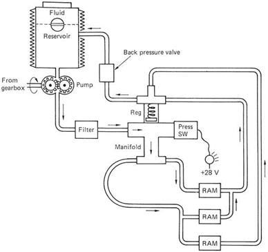
Fig. 6.42 Hydraulic system of the Bell 206 is not duplicated as the machine can be flown manually in the case of failure.
|
|
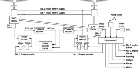
Fig. 6.43 Hydraulic system of the CH-47 is fully powered and extensively duplicated. An APU is also provided to allow hydraulic pressure to be available without the rotors turning.
|
glass allows the level to be checked. The reservoir feeds a constant flow pump driven from the main gearbox so that power is still available during autorotation. The pump output passes through a filter to remove contamination and is fed to the manifold. This unit contains a pressure relief valve to allow fluid back to the reservoir when the pump delivery exceeds demand. The manifold also acts as a connection point for the flow and return pipes to the rams. A pressure switch on the manifold operates a warning light should the pressure fall.
Figure 6.43 shows the hydraulic system of the CH-47. This large transport has tandem rotors of such size that fully powered controls are mandatory. The machine has twin engines and an APU (auxiliary power unit) intended for ground operation. There are three hydraulic systems, No. 1 and No. 2 flight systems and a utility system. All three systems are permanently pressurized to prevent pump cavitation and a small hand pump is provided to allow refilling from a central location. No. 1 system is driven by a pump on the front transmission; No. 2 by a pump on the rear transmission. The APU has a motor/pump unit and there is a further pump on the aft transmission. Utility pressure is then available if the rotors are turning or if the APU is running. All three systems have variable displacement pumps driven by pressure regulators and have filters, accumulators and oil coolers. The utility system has more accumulator capacity because it is used to start the APU using the motor/pump. The APU will recharge the starting accumulator when it is running, but a hand pump is provided in case pressure has been lost.
The utility system provides all non-flight critical hydraulic power and drives the undercarriage steering, swivel centring and locking and the wheel brakes, the winch, the cargo door and ramp actuators and the cargo hook release as well as driving hydraulic motors for main engine starting. In addition, power transfer units allow the utility system to pressurize the flight systems so that these can then be operated without the main engines running or the rotors turning. A power transfer unit consists of an hydraulic motor driving an hydraulic pump. This allows the hydraulic fluid circuits to be kept separate.
The pilot can isolate the ramp actuators and the brake/steering circuits in case of damage or failure so that utility power remains available. The brake system contains a small accumulator so that limited brake operation is still possible after a utility failure.
The hydraulic display panel shows for each system the level in the reservoir, the oil pressure and temperature. There are warning lights for each of the four pumps and warning lights operated by excessive pressure drop across the filters.
 |
Health and Usage Monitoring Systems are an important development that promises improved safety and running costs. The use to which helicopters are put varies tremendously. This means that the wear and fatigue suffered are difficult to assess simply from a flight hour timer. As a result components have to be conservatively lifed so that no failures occur whatever the circumstances. This means that a machine used in an undemanding role has to replace parts that are still serviceable at the same rate as a machine in arduous service that has worn the parts out. The solution is to assess the actual conditions of service of each machine so that the degree of wear on major components can be predicted. In this aspect of HUMS, sensors are located at strategic points and the stresses on the machine are recorded.
The unacceptability of failure leads to the regular replacement of parts. However, not all parts fail instantly. Many components deteriorate gradually and do not actually fail. In others failure is preceded by symptoms that are often present for some time before the failure itself. For example, a failure may result from a crack. Cracks tend to start slowly and propagate at increasing speed as the remaining material lessens. If it is possible reliably to detect those symptoms, an early warning of a failure can be given. For example, gears and bearings make slight characteristic vibrations when they are working normally, but these will change in the case of a defect. The presence of a crack will alter the way a device vibrates. By analysing the vibrations from a gearbox, it is possible to determine if a part is failing and even to suggest which part. Given that most helicopter flights are quite short, if the vibration analysis is sufficiently sensitive the failure will be anticipated sufficiently in advance that the flight can be completed. A more sophisticated analysis could determine the rate of deterioration and suggest a precautionary landing.
7
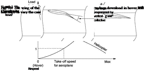


![]()
![]()
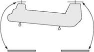

![]()

![]()
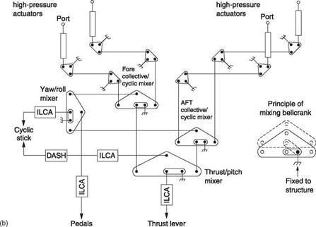
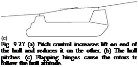
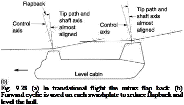

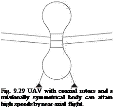


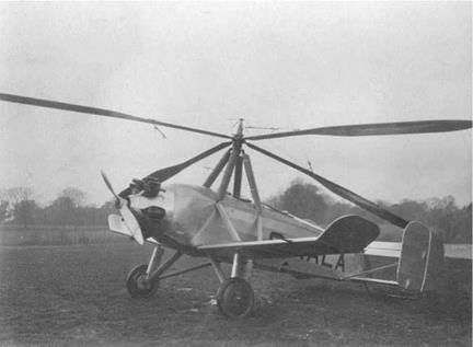
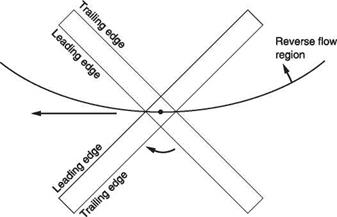
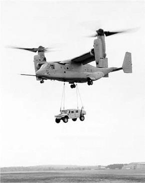
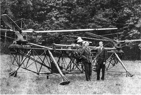
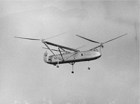
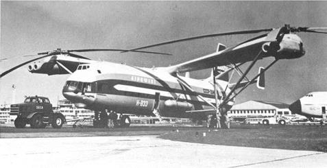
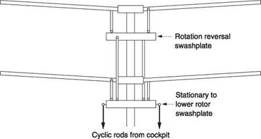
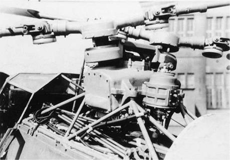
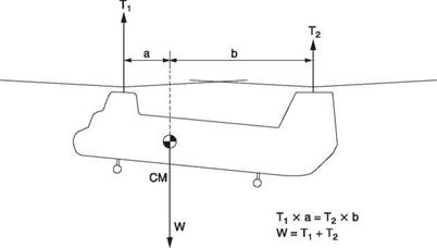
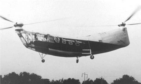

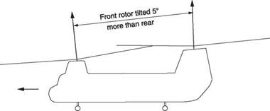
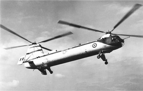


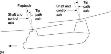
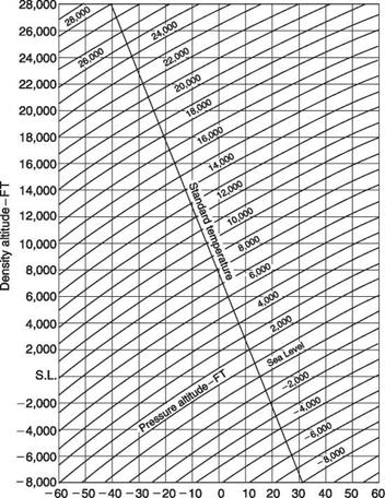
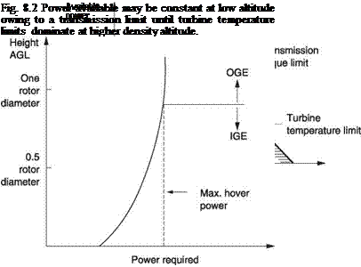
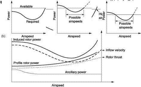
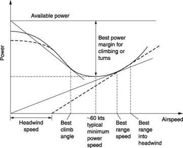
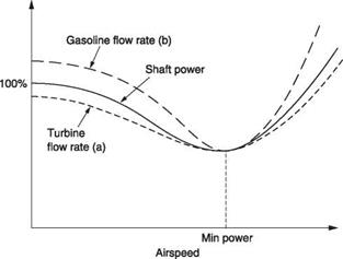
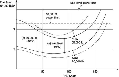
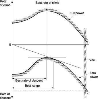
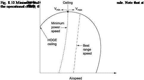
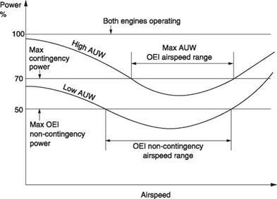
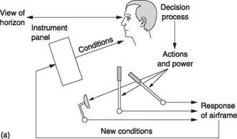
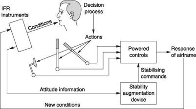


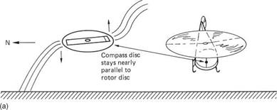

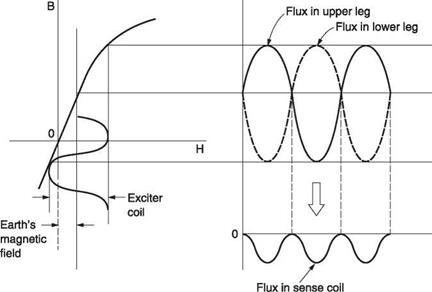
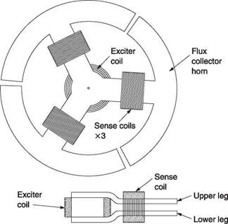
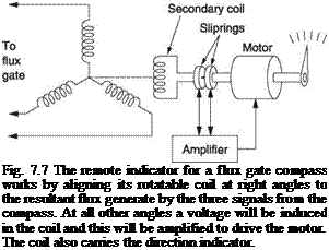
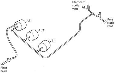
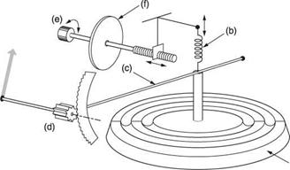
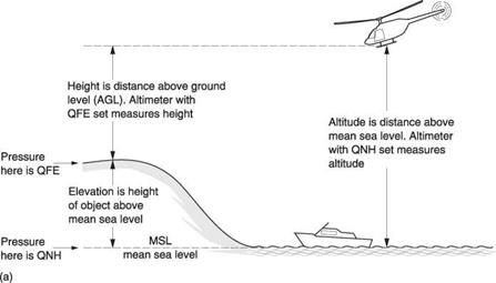
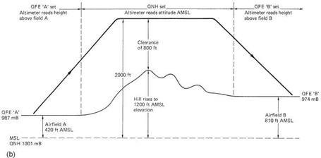
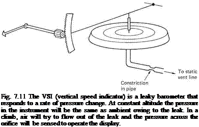
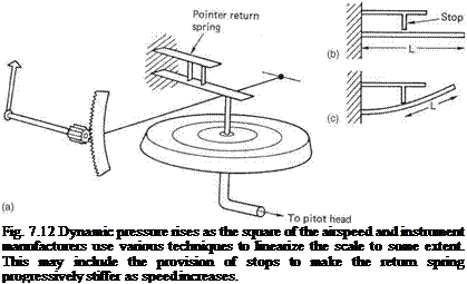
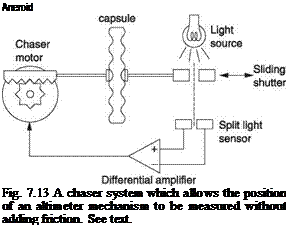
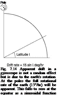
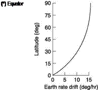
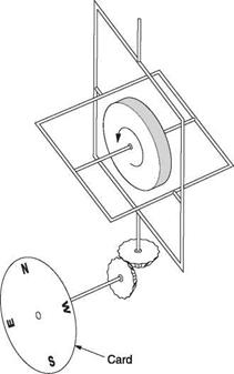
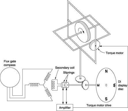
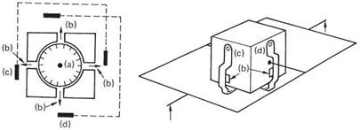
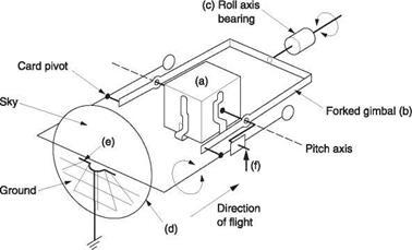
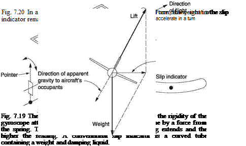
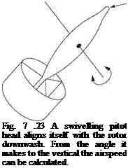
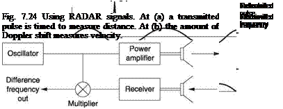
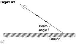
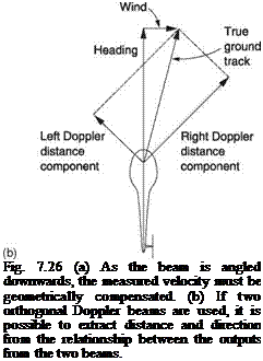
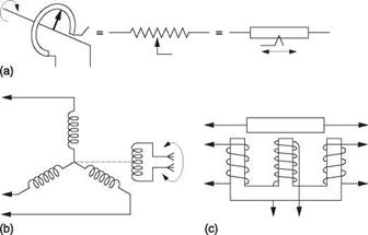
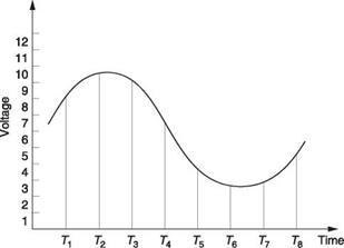
 This bit represents

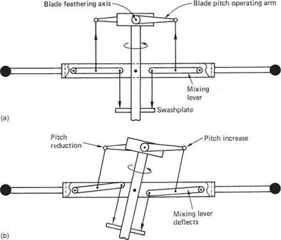
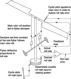
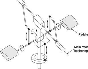
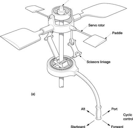
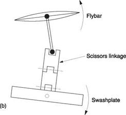
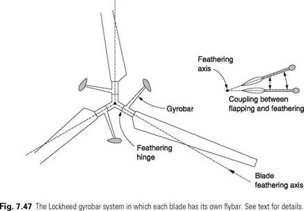

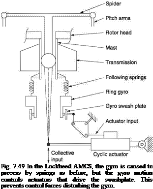
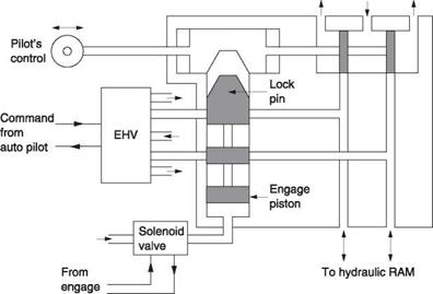
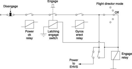


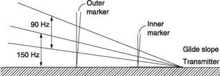
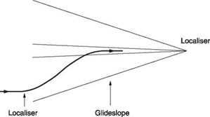

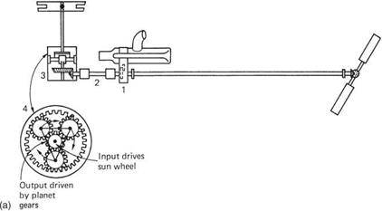
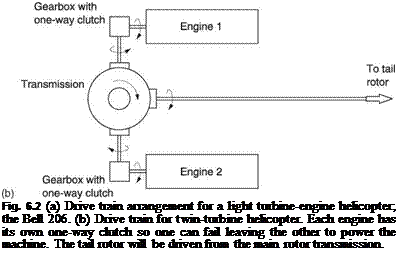
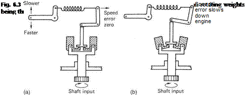

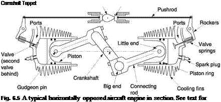

 Magnet
 The oil system is responsible for lubrication and cooling of the moving parts of the engine. Heavy forces are involved in the connecting rods and crankshaft bearings, and if metal-to-metal contact took place the life of the parts would be very short. Oil possesses viscosity, which is a resistance to flow. If viscous oil is pumped between two surfaces it can carry a load without them touching because the viscosity resists the oil being squeezed out. The relative movement of the surfaces causes shearing of the oil. Shearing a viscous liquid develops heat, and this heat load adds to the heat picked up where the oil is used to cool parts of the engine. An oil cooler is necessary to control the oil temperature.


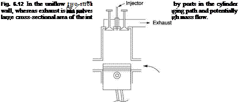

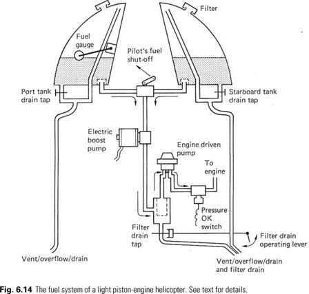
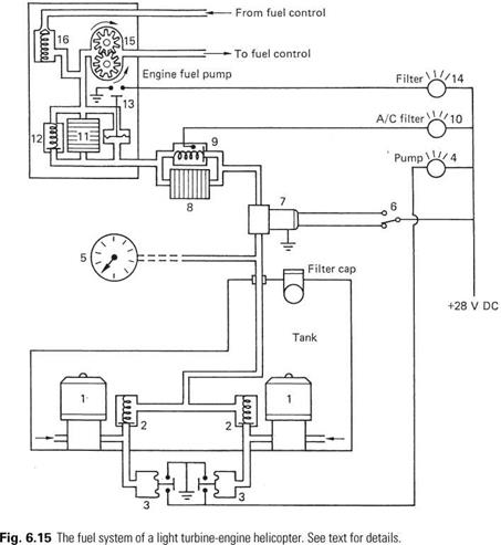


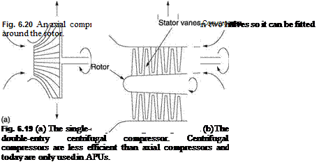


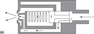
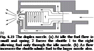
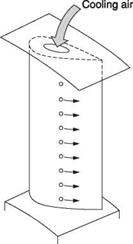


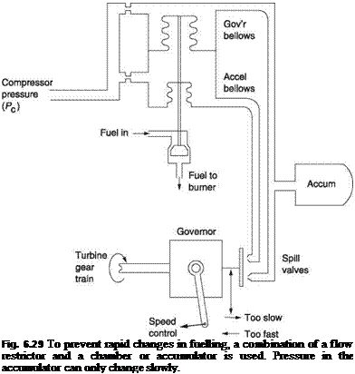
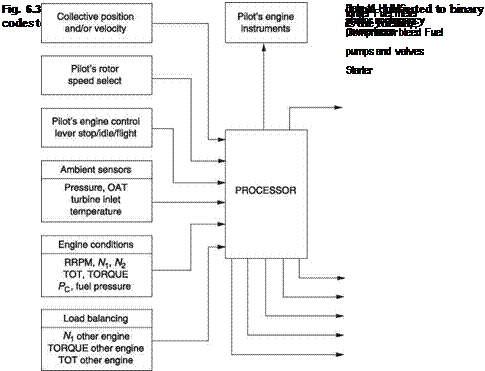


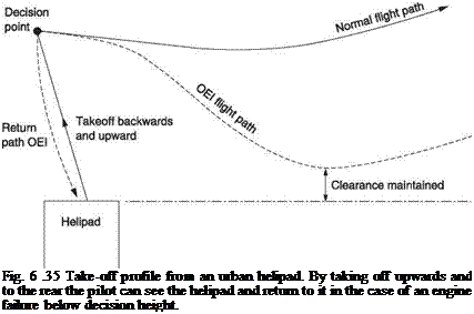
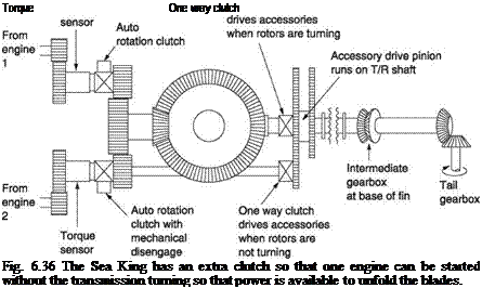
 (a) Engine and rotors


 Alternator

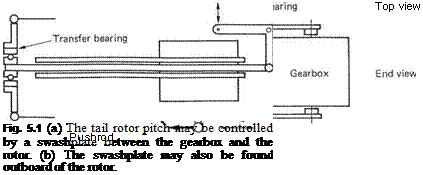
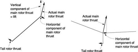
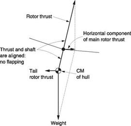
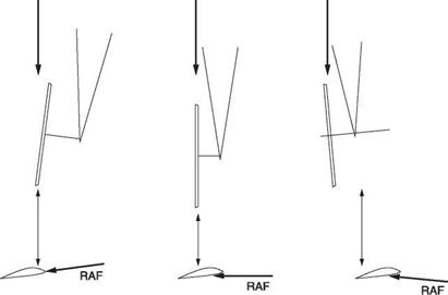
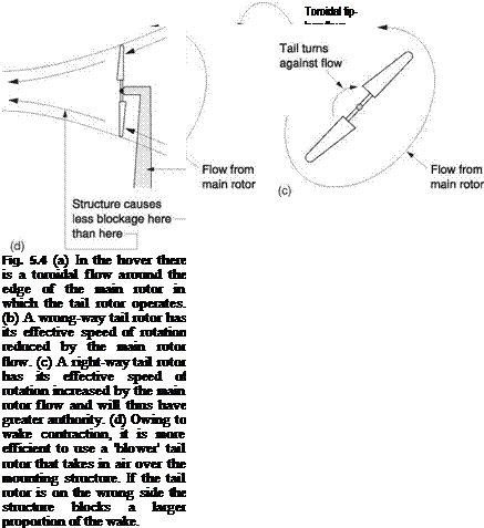
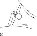
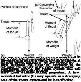

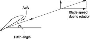
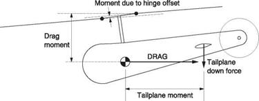
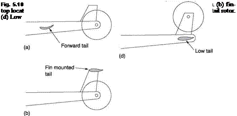
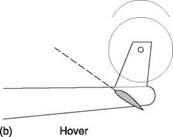
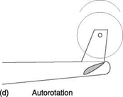
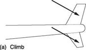
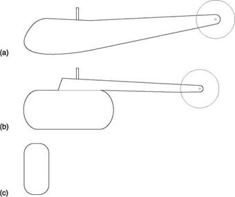
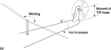


 Sidethrust opposing tail rotor
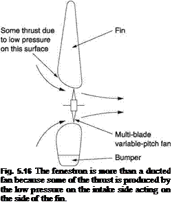
 Turning blade will be straight
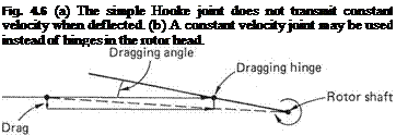
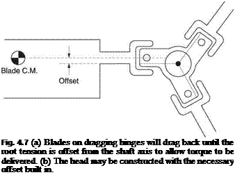
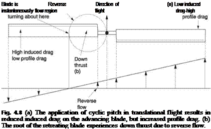
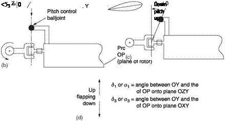

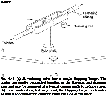

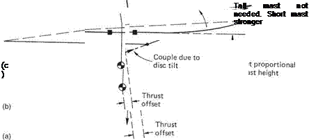
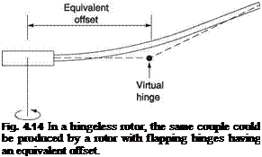



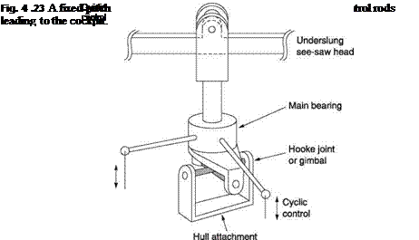


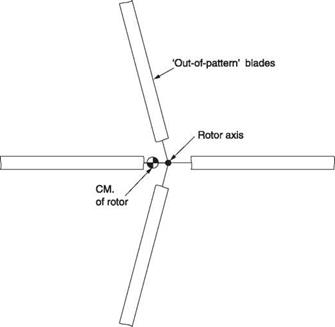


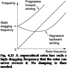

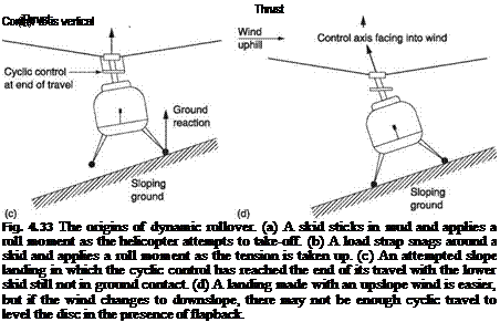


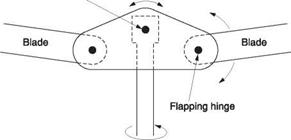
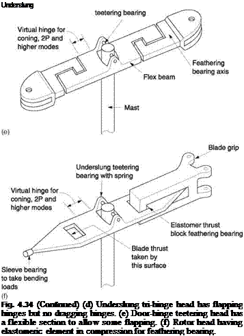
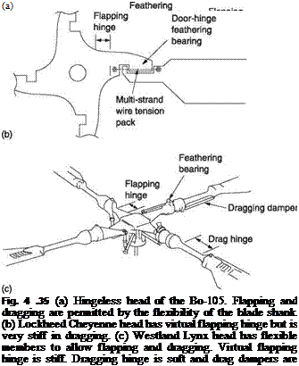
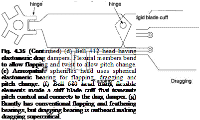







 (a)
(a)
 (b)
(b)