Our heavyweight helicopter equal in the world does not have
In Rostov started production of the most load-lifting rotary-wing car The Russian holding «Helicopt[...]

Everything about aircrafts and helicopters. News and events in aviation worldwide. Civil, transportation, military helicopters and airplanes.

Everything about aircrafts and helicopters. News and events in aviation worldwide. Civil, transportation, military helicopters and airplanes.

Everything about aircrafts and helicopters. News and events in aviation worldwide. Civil, transportation, military helicopters and airplanes.

Everything about aircrafts and helicopters. News and events in aviation worldwide. Civil, transportation, military helicopters and airplanes.


2.1 Introduction
Gases and liquids are generally termed fluids. Though the physical properties of gases and liquids are different, they are grouped under the same heading since both can be made to flow unlike a solid. Under dynamic conditions, the nature of the governing equations are the same for both gases and liquids. Hence, it is possible to treat them under the same heading, namely, fluid dynamics or fluid mechanics. However, certain substances known as viscoelastic materials behave like a liquid as well as a solid, depending on the rate of application of the force. Pitch and silicone putty are typical examples of viscoelastic material. If the force is applied suddenly, the viscoelastic material will behave like a solid, but with gradually applied pressure the material will flow like a liquid. The flow of such materials is not considered in this book. Similarly, non-Newtonian fluids, low-density flows, and two-phase flows such as gas liquid mixtures are also not considered in this book. The theory presented in this book is for well-behaved simple fluids such as air.
2.2 Properties of Fluids
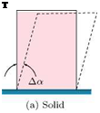
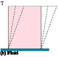
Fluid may be defined as a substance which will continue to change shape as long as there is a shear stress present, however small it may be. That is, the basic feature of a fluid is that it can flow, and this is the essence of any definition of it. Examine the effect of shear stress on a solid element and a fluid element, shown in Figure 2.1.
It is seen from this figure that the change in shape of the solid element is characterized by an angle Да, when subjected to a shear stress, whereas for the fluid element there is no such fixed Да, even for an infinitesimal shear stress. A continuous deformation persists as long as shearing stress is applied. The rate of deformation, however, is finite and is determined by the applied shear force and the fluid properties.
2.2.1 Pressure
Pressure may be defined as the force per unit area which acts normal to the surface of any object which is immersed in a fluid. For a fluid at rest, at any point the pressure is the same in all directions. The pressure in a stationary fluid varies only in the vertical direction, and is constant in any horizontal plane. That is, in stationary fluids the pressure increases linearly with depth. This linear pressure distribution is called hydrostatic pressure distribution. The hydrostatic pressure distribution is valid for moving fluids, provided there is no acceleration in the vertical direction. This distribution finds extensive application in manometry.
Theoretical Aerodynamics, First Edition. Ethirajan Rathakrishnan.
© 2013 John Wiley & Sons Singapore Pte. Ltd. Published 2013 by John Wiley & Sons Singapore Pte. Ltd.
Figure 2.1 Solid and fluid elements under shear stress.
When a fluid is in motion, the actual pressure exerted by the fluid in the direction normal to the flow is known as the static pressure. If there is an infinitely thin pressure transducer which can be placed in a flow field without disturbing the flow, and made to travel with the same speed as that of the flow then it will record the exact static pressure of the flow. From this stringent requirement of the probe for static pressure measurement, it can be inferred that exact measurement of static pressure is impossible. However, there are certain phenomena, such as “the static pressure at the edge of a boundary layer is impressed through the layer" which are made use of for the proper measurement of static pressure. The pressure which a fluid flow will experience if it is brought to rest, isentropically, is termed total pressure. The total pressure is also called impact pressure. The total and static pressures are used for computing flow velocity.
Since pressure is intensity of force, it has the dimensions:
![]()
 |
 |
Force _ MLT-2 Area L2
and is expressed in the units of newton per square meter (N/m2) or simply pascal (Pa). At standard sea level condition, the atmospheric pressure is 101325 Pa, which corresponds to 760 mm of mercury column height.
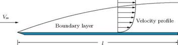
Boundary layer is a thin layer, adjacent to a solid surface, in which the flow velocity increases from zero to about 99% of the freestream velocity, as shown in Figure 1.14.
The boundary layer may also be defined as a thin layer adjacent to a solid surface where the viscous effects are predominant. Thus, inside the boundary layer the effect of viscosity is predominant. Outside the boundary layer the effect of viscosity is negligible. Also, greater the Reynolds number the thinner will be the boundary layer, and we have practically the case of an inviscid flow past an object. But, however small the viscosity may be, the plate is subjected to a tangential traction or drag force acting in the direction of flow velocity. This force is known as the skin friction or the frictional drag, and this force can never be completely eliminated. On the other hand, the flow outside the boundary layer behaves like an inviscid flow.
|
Ко
Figure 1.14 Boundary layer on a flat plate. |
|
Figure 1.15 An aerofoil in an uniform flow. |
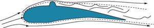
For flow past a bluff body, such as a circular cylinder, an eddying wake forms behind the cylinder, greatly increasing the drag. The problem of flow separation or break away of the boundary layer from a bluff body can be minimized by streamlining the body. For properly streamlined bodies the boundary layer will not break away and the wake will remain almost insignificant. This has been achieved in the profiles like that shown in Figure 1.15 which are generally referred to as aerofoils.
For aerofoils there is a narrow wake but, to a first approximation, the problem of the flow past such a streamlined shape can be assumed as an inviscid flow past the body. In other words, the flow past an aerofoil can be regarded as flow without wake. The above considerations give rise to the following general observations:
1. It is found that to delay the breaking away of the boundary layer from the region where the fluid is moving against increasing pressure (that is, adverse pressure gradient, as in the case of the rear of a circular cylinder) the flow should turn as gradually as possible. To enable this gradual turning of flow, the body should have a large radius of curvature.
2. It is essential to keep the surface of the object smooth, because even small projections above the surface (in general) may disturb the boundary layer considerably, causing a breaking away of the flow. Furthermore, a projection such as a rivet, whose head projects above the boundary layer, may entirely alter the character of the flow. An exaggerated flow over an aerofoil with such a rivet head is schematically shown in Figure 1.16.
3. Good streamlined shapes will have the breaking away of the flow just close to the trailing edge.
|
Figure 1.16 Flow separation caused by a rivet head projection. |
1.10 Summary
Aerodynamics is the science concerned with the motion of air and bodies moving through air. In other words, aerodynamics is a branch of dynamics concerned with the steady motion of air, particularly when it interacts with a moving object. The forces acting on the bodies moving through the air are termed aerodynamic forces.
The aerodynamic force Fad can be resolved into two component forces, one at right angles to V and the other opposite to V. The force component normal to V is called lift L and the component opposite to V is called drag D.
A streamlined body is that for which the skin friction drag accounts for the major portion of the total drag, and the wake drag is very small.
A bluff body is that for which the wake drag accounts for the major portion of the total drag, and the skin friction drag is insignificant.
The main lifting system of an aircraft consists of two wings which together constitute the aerofoil. The tail plane also exerts lift. The ailerons on the right and left wings, the elevators on the horizontal tail, and the rudder on the vertical tail are control surfaces.
The distance between the wing tips is called the span. The section of a wing by a plane parallel to the plane of symmetry is called a profile.
Chord of any profile is generally defined as an arbitrarily fixed line drawn in the plane of the profile. The chord has direction, position, and length.
For a cylindrical aerofoil (that is, a wing for which the profiles are the same at every location along the span), the chord of the aerofoil is taken to be the chord of the profile in which the plane of symmetry cuts the aerofoil. In all other cases, the chord of the aerofoil is defined as the mean or average chord located in the plane of symmetry.
The aspect ratio of a wing is the ratio of its span 2b to chord c.
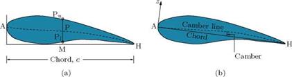
• Camberline of an aerofoil is essentially the bisector of its thickness.
• Camber is the deviation of the camberline from the chord, namely the shortest line joining the leading and trailing edges of the aerofoil profile.
• The local camber can vary continuously from the leading edge to the trailing edge. Therefore, the maximum camber is taken as the representative camber. That is, the maximum ordinate of the camberline from the chord is taken as the camber of an aerofoil.
When an aircraft travels in the plane of symmetry (that is, the direction of flight is parallel to the plane of symmetry), the angle between the direction of motion and the direction of the chord of a profile, is called the geometrical incidence of the profile, denoted by the Greek letter a. The angle a is also called angle of attack.
Aerodynamic force on an aircraft is the force due to the pressure distribution around it, caused by the motion of the aircraft. Thus, the gravity does not enter into the specification of aerodynamic force.
Mach number is the ratio of local flow speed to the local speed of sound or the ratio of inertial force to elastic force. It is a measure of compressibility. For an incompressible fluid the M = 0.
The dimensionless group (Vl/v) is called the Reynolds number Re. Reynolds number is the ratio of inertial force to viscous force. For an inviscid fluid Re = to. For air, v is small and Re is large unless Vl is small.
The dimensionless number:
is called the (dimensionless) coefficient of the aerodynamic force Fad.
The important aerodynamic forces and moment associated with a flying machine, such as an aircraft, are the lift L, the drag D, and the pitching moment M. The lift and drag forces can be expressed as dimensionless numbers, popularly known as lift coefficient CL and drag coefficient CD, by dividing L and D with 1 pV2S. Thus:
![]()
![]() L
L
2 pV 2S
D
2 pV 2S
The pitching moment, which is the moment of the aerodynamic force about an axis perpendicular to the plane of symmetry (about y-axis in Figure 1.3), will depend on the particular axis chosen. Denoting the pitching moment about the chosen axis by M (note that M is also used for denoting Mach number, which is the ratio of local flow speed and local speed of sound), we define the pitching moment coefficient as:
Boundary layer is a thin layer, adjacent to a solid surface, in which the flow velocity increases from zero to about 99% of the freestream velocity. The boundary layer may also be defined as a thin layer adjacent to a solid surface where the viscous effects are predominant. Thus, inside the boundary layer the effect of viscosity is predominant. Outside the boundary layer the effect of viscosity is negligible.
For flow past a bluff body, such as a circular cylinder, an eddying wake forms behind the cylinder, greatly increasing the drag. The problem of flow separation or break away of the boundary layer from a bluff body can be minimized by streamlining the body. For properly streamlined bodies the boundary layer will not break away and the wake will remain almost insignificant.
Exercise Problems
1. An aircraft of total mass 10000 kg cruises steadily at an altitude. If the aerodynamic efficiency is 4, find the thrust required to propel the aircraft.
[Answer: 24.525 kN]
2. An aircraft of mass 3000 kg in a steady level flight is at an angle of incidence of 5° to the freestream. Determine the thrust generated by the engine.
[Answer: 2574.8 N]
3. An aircraft weighing 200 kN is in level flight at sea level with a speed of 600 km/h. The wing span and chord are 8 m and 1.8 m, respectively. Determine the lift coefficient of the wing.
[Answer: 0.816]
4. Determine the speed of sound in air at sea level conditions.
[Answer: 340.3 m/s]
5.
If the aerodynamic efficiency of an aircraft in a steady flight is 10, determine the incidence of the wing to the freestream direction.
6. A sail plane of mass 270 kg flies straight and level with an incidence of 4°. Determine the aerodynamic force acting on the wings and the aerodynamic efficiency.
[Answer: 2655.17 N, 14.30]
7. A wing of rectangular planform has 10 m span and 1.2 m chord. In straight and level flight at 240 km/h the total aerodynamic force acting on the wing is 20 kN. If the aerodynamic efficiency of the wing is 10, calculate the lift coefficient. Assume air density to be 1.2 kg/m3.
[Answer: CL = 0.622]
Reference
1. Rathakrishnan, E., Applied Gas Dynamics, John Wiley & Sons Inc., New Jersey, 2010.
![]()
|
L 2 pV 2S |
|
D 2 pV 2S |
The important aerodynamic forces and moment associated with a flying machine, such as an aircraft, are the lift L, the drag D, and the pitching moment M. The lift and drag forces can be expressed as dimensionless numbers, popularly known as lift coefficient CL and drag coefficient CD, by dividing L and D with 2pV2S. Thus:
|
pV2 Sc |
The variation of CL and CD with the geometrical incidence a is shown in Figure 1.13. The pitching moment, which is the moment of the aerodynamic force about an axis perpendicular to the plane of symmetry (about y-axis in Figure 1.3), will depend on the particular axis chosen. Denoting the pitching moment about the chosen axis by M (note that M is also used for denoting Mach number, which is the ratio of local flow speed and local speed of sound), we define the pitching moment coefficient as:
where c is the chord of the wing. A typical variations of CL, CD and CM with angle of attack a are shown in Figure 1.13.
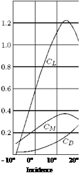 |
Note that the aerodynamic coefficients CL, the drag CD and the moment CM are dimensionless parameters.
Figure 1.13 Variation of lift, drag and pitching moment coefficients with geometrical incidence.
Example 1.4
An aircraft weighing 20 kN is in level flight at an altitude where the pressure and temperature are 45 kPa and 0 °C, respectively. If the flight speed is 400 km/h and the span and mean chord of the wings are 10 m and 1.5 m, determine the lift coefficient.
Solution
Given, W = 20, 000 N, 2b = 10 m, c = 1.5 m, V = 400/3.6 = 111.11 m/s, p = 45 kPa, T = 0 + 273.15 = 273.15 K.
The density of air is:
![]() p
p
RT
45, 000
= 287 x 273.15 = 0.574 kg/m3.
The planform area of the wing is:
S = 2b x c = 10 x 1.5 = 15m2.
In level flight, the weight of the aircraft is equal to the lift. Thus:
L = 20, 000 N.
Therefore, by Equation (1.4a), the lift coefficient becomes:
![]() L
L
2 pV 2S
20, 000
2 x 0.574 x 11 1.11 2 x 1 5
From our studies on similarity analysis in fluid mechanics, we know that, for dynamic similarity between the forces acting on an actual (or full-scale) machine and a scaled-down model used for testing (usually wind tunnel tests), the actual machine and the scale model must satisfy geometric and kinematic similarities. Thus, the test model and the actual machine should be geometrically similar, and if the model tests give an aerodynamic coefficient Cad, m for a test conducted at a Reynolds number Rem, the scale effect on the aerodynamic force coefficient Cad of the actual machine is given by:
Cad f (Re)
Cad, m f (Rem)
where Re is the Reynolds number of the flow around the actual machine and Rem is the Reynolds number of the flow around the model. The model tests will give aerodynamic coefficient (Cad = Cad, m) directly, if Re = Rem. If the viscosity p and density p are kept the same in the flow fields of the actual machine and its scale model, then both the flow velocity V and the characteristic length (for example, chord for an aerofoil) should be adjusted in such a way to keep Re = Rem. But the characteristic length lm for the model will be, usually, smaller than the l for the actual machine. Therefore, the test speed for the model has to be greater than the speed of the actual machine.
If there is provision to use compressed air wind tunnel, then the density p also can be increased to adjust the model Reynolds number to match the Reynolds number of the actual machine. In this kind of studies, it is essential to make a statement about the length scale used for calculating the Reynolds number.
Example 1.3
An aircraft wing profile has to be tested in a wind tunnel. If the actual wing of mean chord 1.2 m has to fly at an altitude, where the pressure and temperature are 50 kPa and 2 °C, respectively, with a speed of 250 km/h. Determine the chord of the wing model to be tested in the wind tunnel, ensuring dynamic similarity, if the test-section conditions are 90 m/s, p = 100 kPa, T = 22 °C.
Solution
Let the subscripts p and m refer to the prototype (actual) wing and the wing model to be tested in the wind tunnel, respectively.
Aerodynamic force acting on an aircraft is the force due to the pressure distribution around it, caused by the motion of the aircraft. Thus, the gravity does not enter into the specification of aerodynamic force. Assuming the motion of the aircraft to be steady without rotation, the aerodynamic force on the wing or on the complete aircraft may be expected to depend on the forward speed V, air density p, speed of sound a and kinematic viscosity v, of the environment in which it is flying, and the total length l of the aircraft.
If the air is assumed to be incompressible and inviscid, we have the density p = constant and the viscosity coefficient p = 0. Therefore, the speed of sound becomes:
a
Assuming the flow over the aircraft to be isentropic, we have:
— = constant.
PY
Differentiating with respect to p, we have:
— = (constant) y P(y 1. dp
P
Now, replacing the “constant” with —-, we get:
dP P (–1)
t = ~y yp(y )
dp pY
YP
p
Substituting this, we get the speed of sound as:
a
For incompressible flow with dp = 0, we have the speed of sound as:
a = <x
For inviscid fluid, the kinematic viscosity becomes:
M n v = — = 0.
P
Therefore, for incompressible flows, the aerodynamic force Fad does not depend on the speed of sound a and kinematic viscosity v. Thus, Fad can be assumed to depend only on p, V and l. The Fad would be given by a formula such as:
![]() Fad = 2 kpaVblc,
Fad = 2 kpaVblc,
![]()
by dimensional theory as follows.
In terms of the fundamental dimensions of mass (M), length (L) and time (T), we can express Equation (1.1) as:
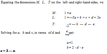
Equating the dimensions M, L, T on the left-hand-side and right-hand-side, we get:
M : 1 = a
L : 1 = -3a + b + c
T : – 2 = – b.
Solving for a, b and c, we get:
a = 1, b = 2, c = 2.
Substituting for a, b, c into Equation (1.1), we get:
![]() Fad = 2 kpV Чг.
Fad = 2 kpV Чг.
This is valid only for steady incompressible and inviscid flows. If we wish to account for compressibility and viscosity, a and v should be included in Equation (1.1) and expressed as:
![]() Fad = ^2 1 к paVblc
Fad = ^2 1 к paVblc
where – ki is a dimensionless number, and each side must have the dimension of force. Here ^ denotes the sum of all allowable terms. In terms of basic dimensions M, L and T, Equation (1.3) becomes:
ML (Ma(Lb r (Ld ( L2 ‘
~r2 = v) r) l t) Y.

 |
Thus, Equation (1.3) becomes:
Fad = X) 2hpV2—d—el2—ei
or
![]() X—^ 1 22 ( V N — ( Vl
X—^ 1 22 ( V N — ( Vl
fad = £ 2- –
The ratio (V/a) is called the Mach number M, which is essentially a dimensionless speed. Mach number is the ratio oflocal Bow speed to the local speed of sound or the ratio of inertial force to elastic force. It is a measure of compressibility. For an incompressible fluid, M = 0.
The dimensionless group (Vl/v) is called the Reynolds number Re. Reynolds number is the ratio of inertial force to viscous force. For an inviscid fluid Re = to. For air, the kinematic viscosity v is small and Re is large unless Vl is small.
Thus, Equation (1.4) becomes:
Fad = 1 pV21253 kxM—d Re—e
= 1 pV2Sf(M, Re),
![]() where l2 has been replaced by f (M, Re) is a function, whose independent of physical units.
where l2 has been replaced by f (M, Re) is a function, whose independent of physical units.
The dimensionless number:
is called the (dimensionless) coefficient of the aerodynamic force Fad. The effect of compressibility can usually be neglected if M < 0.3, and the flow is termed incompressible. Thus, for an incompressible flow, the aerodynamic force coefficient is a function of Reynolds number only. That is:
CFad = f (Re).
At this stage, we may wonder about the definition of incompressible flow. The mathematical definition of incompressible flow is that “it is a flow with Mach number zero.” But it is obvious that, for M = 0, the flow velocity is zero, and hence there is no flow. But mathematics, as an abstract science, stipulates the limit of M = 0, with the sole idea of rendering the density to become invariant. But when V = 0, engineering science will declare it as a stagnant field and not as a flow field. Therefore, the engineering definition of incompressible flow is drastically different from the mathematical definition. From an engineering point of view, when the density change associated with V is insignificant the flow can be termed incompressible. Also, for engineering applications, any change less than 5% is usually regarded as insignificant. With this consideration, any flow with density change less than 5% can be called incompressible. For air flow at standard sea level conditions (p = 101325 Pa and T = 288 K), 5% density change corresponds to M = 0.3 [1]. Therefore, flows with Mach number less than 0.3 are regarded as incompressible flows and the density p0 corresponding to the stagnation state is taken as the density of an incompressible flow.
When an aircraft travels in the plane of symmetry (that is, the direction of flight is parallel to the plane of symmetry), the angle between the direction of motion and the direction of the chord of a profile, as shown in Figure 1.12, is called the geometrical incidence of the profile, denoted by the Greek letter a. The angle a is also called angle of attack.
For an airplane as a whole the geometrical incidence will be defined as the angle between the direction of motion and the chord of the aerofoil. When the chords of various profiles of a wing are parallel the incidence is the same at each section. When the chords are not parallel the incidence varies from section to section and the wing has twist. The value of the geometrical incidence would be altered if a different line were chosen as chord.
In this situation, it will be beneficial to understand the difference between the wing with the chords of its profiles at different locations along the span parallel to each other and the wing with the chords of its
 Ch°irl &
profiles at different locations along the span not parallel. We know that the profiles are the cross-sections of the wing geometry, at different locations of the span, in planes parallel to the mid-plane (xz-plane in Figure 1.3) passing through the nose and tail tips of the airplane. Therefore, only for a wing which has its left and right wings parallel to the y-axis in Figure 1.3 the chords of its profile will be parallel, and the wing will be termed cylindrical wing. For a wing with its left and right parts not parallel to the y-axis, the chords will not be parallel, and the wing will be termed a twisted wing.
Camber is the maximum deviation of the camber line (which is the bisector of the profile thickness) from the chord of the profile, as illustrated in Figure 1.11.
Let zu and zi be the ordinates on the upper and lower parts of the profile, respectively, for the same value of x. Let c be the chord, and the x-axis coincide with the chord. Now, the upper and lower camber are defined as:
![]()
 |
Upper camber = Lower camber
where the subscript “max” refers to that ordinate which is numerically the greatest. Camber is taken as positive or negative according to the sign of (zM)max and (z;)max. Also, at a given x, the magnitudes of (zu)max and (zl)max may be different for unsymmetrical profiles.
The camber line is defined as the locus of the point (x, 2 (zu + zi)). In the case of symmetrical profile zu + zl — 0, and the camber line is straight and coincides with the chord. Denoting the numerically greatest ordinate of the camber line by zmax, we define:
Mean camber = ^max.
c
Note that the mean camber, in general, is not the same as the mean of upper and lower camber, and the mean camber of a symmetrical profile is zero. Usually the word camber refers to the mean camber.
The thickness ratio of an aerofoil is the ratio of the maximum thickness (measured perpendicular to the chord) to the chord. The thickness ratio is essentially tmax/c.
From the above discussions, it is evident that:
• Camberline of an aerofoil is essentially the bisector of its thickness.
• Camber is the deviation of the camberline from the chord, namely the shortest line joining the leading and trailing edges of the aerofoil profile.
• The local camber can vary continuously from the leading edge to the trailing edge. Therefore, the maximum camber is taken as the representative camber. That is, the maximum ordinate of the camberline from the chord is taken as the camber of an aerofoil.
• The thickness of an aerofoil profile also varies continuously from the leading edge to the trailing edge. Therefore, the ratio of the maximum thickness:
tmax — i^Zu, max + Zl, max )/2
to chord c is used to represent the thickness-to-chord ratio of an aerofoil.
Aspect ratio of a wing is the ratio of its span 2b to chord c. Consider a cylindrical wing shown in Figure 1.10. Imagine this to be projected on to the plane (xy-plane), which contains the chords of all the sections (this plane is perpendicular to the plane of symmetry (xz-plane) and contains the chord of the wing). The projection in this case is a rectangular area S, say, which is called the plan area of the wing. The plan area is different from the total surface area of the wing. The simplest cylindrical wing would be a rectangular plate, and the plan area would then be half of the total surface area.
The aspect ratio of the cylindrical wing is then defined by:
M=2_b=
c S,
where S — span x chord — 2b x c.
In the case of a wing which is not cylindrical, the plan area is defined as the area of the projection on the plane through the chord of the wing (mean chord) perpendicular to the plane of symmetry, and the aspect ratio is defined as:
![]() (2b)2
(2b)2
S
A representative value of aspect ratio is 6.
Example 1.2
The semi-span of a rectangular wing of planform area 8.4 m2 is 3.5 m. Determine the aspect ratio of the wing.
Solution
Given, S = 8.4 m2 and b = 3.5 m.
The planform area of a wing is S = span x chord. Therefore, the wing chord becomes:
![]() c =
c =
The aspect ratio of the wing is:
![]() Span Chord 2 x 3.5
Span Chord 2 x 3.5
1.2
For a cylindrical aerofoil (that is, a wing for which the profiles are the same at every location along the span, as shown in Figure 1.5), the chord of the aerofoil is taken to be the chord of the profile in which the plane of symmetry cuts the aerofoil. In all other cases, the chord of the aerofoil is defined as the mean or average chord located in the plane of symmetry.
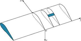
Let us consider a wing with rectangular Cartesian coordinate axes, as shown in Figure 1.10. The x-axis, or longitudinal axis, is in the direction of motion, and is in the plane of symmetry; the y-axis, or lateral
|
|
axis, is normal to the plane of symmetry and along the (straight) trailing edge. The z-axis, or normal axis, is perpendicular to the other two axes in the sense that the three axes form a right-handed system. This means, in particular, that in a straight horizontal flight the z-axis will be directed vertically downwards. Consider a profile whose distance from the plane of symmetry is |y|. Let c be the chord length of this profile, в be the inclination of the chord to the xy plane, and (x, y, z) be the coordinates of the quarter point of the chord, that is, the point of the chord at a distance c/4 from the leading edge of the profile. This point is usually referred to as the quarter chord point. Since the profile is completely defined when y is given, all quantities characterizing the profile, namely, the mean chord, its position and inclination to the flow, are functions of y.
The chord of an aerofoil is defined by averaging the distance between the leading and trailing edges of the profiles at different locations along the span. Thus, if cm is the length of the mean chord, (xm, 0, zm) its quarter point, and вт its inclination, we take the
These mean values completely define the chord of the aerofoil in length (cm), direction (em), and position
(xm, zm).
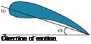
A chord of any profile is generally defined as an arbitrarily fixed line drawn in the plane of the profile, as illustrated in Figure 1.8. The chord has direction, position, and length. The main requisite is that in each case the chord should be precisely defined, because the chord enters into the constants such as the lift and drag coefficients, which describe the aerodynamic properties of the profile. For the profile shown in Figure 1.8(a), the chord is the line joining the center of the circle at the leading and trailing edges.
For the profile in Figure 1.8(b), the linejoining the center of the circle at the nose and the tip of the tail is the chord. For the profile in Figure 1.8(c), the line joining the tips of leading and trailing edges is the chord.
|
(a) Leading and trailing edges are circular arcs. |
|
(b) Circular arc leading edge and sharp trailing edge. |
|
(c) Faired leading edge and sharp trailing edge. Figure 1.8 Illustration of chord for different shapes of leading and trailing edges. |
|
———— Chord c——————— Figure 1.9 Chord of a profile. |
A definition which is convenient is: the chord is the projection of the profile on the double tangent to its lower surface (that is, the tangent which touches the profile at two distinct points), as shown in Figure 1.9. But this definition fails if there is no such double tangent.