Category Theoretical and Applied Aerodynamics

Numerical Method for the Solution of Boundary Layer Equations

A Cartesian mesh system is defined, with constant steps Ax and Ay and indices i and j in the x – and y-directions, respectively. This is an initial/boundary value problem. Before the obstacle, a uniform flow is specified ui, j = U, vi, j = 0, j = 1, jx. The pressure gradient or source term is specified from the inviscid flow solution. The continuity equation is used to solve for v and the momentum equation for u. Consider the x-momentum equation:

Подпись:_du _du dui d2 u

dx + p – y = >m~du + >‘dy

where u and v are evaluated from previous iteration (for initial guess, extrapolate from previous line). Two boundary conditions are specified for u, i. e.

Подпись: (8.39)У1 = 0, ui,1 = 0, yjx = h, ui, jx = U, i = 2,…

h is the ordinate of the upper boundary, h > 5(l), large enough to include the boundary layer.

Central finite differences are used for the first and second partial derivatives of u in y

Подпись:Numerical Method for the Solution of Boundary Layer EquationsПодпись:Numerical Method for the Solution of Boundary Layer Equations

Подпись: ui, j - ui-1, j Ax Подпись: i = 2,..., j = 2,..., jx — 1 Подпись: (8.41)
Numerical Method for the Solution of Boundary Layer Equations

and i

A tridiagonal solver is used to obtain ui, j for line i = 2,…

Note that, as long as ui, j > 0, the tridiagonal matrix is diagonally dominant, which insures stability with respect to round-off errors.

Consider next the continuity equation to solve for v. One boundary condition is specified

Подпись: (8.42)У1 = 0, v;,1 = 0, i = 2,…

Numerical Method for the Solution of Boundary Layer EquationsПодпись: i,jПодпись: (

Numerical Method for the Solution of Boundary Layer Equations
Подпись: Ax

The following scheme is used

Подпись: (8.43)i = 2,…, j = 1,…, jx — 1

This equation is marched upward along the vertical line, solving for vi, j+1.

The process is repeated, i. e. one iterates on u and v on line i until convergence (3 or 4 iterations). Then, one marches to the next line i + 1. The domain is swept once in the flow direction.

Boundary Layer over a Flat Plate

Подпись: S(x) x Boundary Layer over a Flat Plate Подпись: (8.37)
Boundary Layer over a Flat Plate Boundary Layer over a Flat Plate

In this special case, the inviscid flow solution is simply ui (x) = U and pi (x) = p™. The pressure gradient vanishes and there is no source term in the boundary layer equations. From the order of magnitude analysis one concludes that

The boundary layer has a parabolic growth. The constant C ~ 5.0. A self-similar solution has been found and calculated accurately by Blasius in 1908, see Ref. [3]. Other approximate solutions have been obtained with von Karman integral equation, see below.

Laminar Boundary Layer Theory (Prandtl 1904)

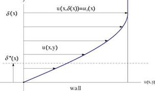
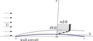
Let S be the boundary layer thickness which represents the limit beyond which viscous effects are negligible. Let l be the characteristic length of the obstacle. We assume that S ^ l, see Fig. 8.6. Inside the boundary layer one can simplify the Navier-Stokes equations, using order of magnitude analysis which is based on the rigorous technique of asymptotic expansion. The м-component of velocity is of order U, the incoming flow velocity. Pressure is assumed to be of order p = O (pU2), in other words, it can be written

Laminar Boundary Layer Theory (Prandtl 1904)

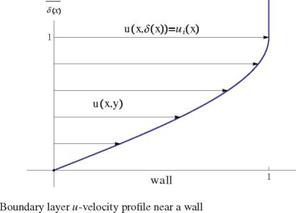
Fig. 8.6 Geometric interpretation of displacement thickness S* (x)

P(x, y) = pu2n(<8 27)

where П is a dimensionless function of x/1 and y/6(x) only. The coefficient in front of the dimensionless function, pU2, is called a “gage”. It gives the order of magnitude of the term. Furthermore, the partial derivatives are of order, respectively:

Laminar Boundary Layer Theory (Prandtl 1904)

d2 d2

dx2 « dy2


(8.28)


Laminar Boundary Layer Theory (Prandtl 1904)

(a) From continuity, the two terms must balance, hence

Laminar Boundary Layer Theory (Prandtl 1904)

(8.29)


The flow is almost aligned with the body.

(b) From the x-momentum equation: the acceleration terms in the left-hand-side are both of order O (pu^j and must balance the viscous term р,^ = о (pjU^j, hence

Laminar Boundary Layer Theory (Prandtl 1904)

(8.30)


Laminar Boundary Layer Theory (Prandtl 1904)

where the Reynolds number is defined as Rel = pU. In fact, this is true for any x sufficiently large, i. e.

Laminar Boundary Layer Theory (Prandtl 1904)

where Rex = pUx. Note that if there is a pressure gradient in the x-direction, its order will match the other terms, as dp = о (p ufsj.

(c) Consider the y-momentum equation. First we multiply it by |: the acceleration terms in the left-hand-side are both now of order O (pир^ and balance the viscous

term of order O (p U^ as a consequence of the previous result (indeed, one term и has been replaced by v in both sides). The pressure derivative term is now of order O (pир. Comparing this term’s magnitude with the other terms indicates that this term dominates the equation since

U2

U262

U2

( 62

l > p 13

= pT

U) *

d p

dv

dv

d2v

dy y> pu dx

+pv d

0Г Pdy-2

As a result, to first order, the y-momentum equation reduces to one term and the pressure gradient in the y-direction must vanish

^ = 0 ^ p = p(x) = pi (x) (8.33)

d y

where the subscript i stands for “inviscid”, i. e. in the inviscid flow. Let ui (x) be the inviscid flow velocity at the edge of the boundary layer. From Bernoulli’s equation

p™ + [7] pU2 = pi (x) + 2p (u2(x) + v2(x)) ~ pi (x) + 2pu2(x) (8.34)

Подпись: dp _ dpi (x) dx dx Laminar Boundary Layer Theory (Prandtl 1904) Подпись: (8.35)

Taking the derivative in the x-direction yields

d2 u

Laminar Boundary Layer Theory (Prandtl 1904) Подпись: (8.36)

Hence the Prandtl boundary layer equations reduce to

This is a nonlinear system of two equations in two unknowns, (u, v) with a source term function of ui (x) provided by the inviscid flow. It is of parabolic type and can be marched in the flow direction as long as u(x, y) > 0.

The initial/boundary conditions are the following:

• at x = 0 u(0, y) = U, v(0, y) = 0, a uniform, undisturbed velocity profile is given,

• at y = 0, u(x, 0) = v(x, 0) = 0, along the solid wall,

• at y = S(x), u (x, S(x)) = ui (x), at the edge of the boundary layer.

Viscous Stresses in 2-D (Cartesian Coordinates)

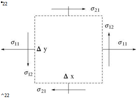
To account for viscous stresses in the momentum equations, consider an element as in the sketch, Fig. 8.4.

The viscous forces in the x-direction are

( Ax Ax

&1,1(x + —, y, t) – ah1(x – —, y, t) Ay

( Ay Ax

+ 02,1 (x, y + -2-, t) – <72,1 (x, y – —, t) Ax (8.13)

Dividing by Ax. Ay and taking the limit gives

д71,1 до2,1

dx + dy

Fig. 8.4 Viscous stresses in 2- D

Подпись: a22 ^22

Similarly, the viscous forces in the y-direction is

Ax Ax

01,2 (x + —, y, t) – 0-1,2(x – —, y, t) Ay

Подпись:( Ay Ax

+ 02,2(X, y + —, t) – 02,2(X, y – —, t) Ax

Again, dividing by Ax. Ay and taking the limit gives

Viscous Stresses in 2-D (Cartesian Coordinates)

(8.16)


Note: taking moments about the centroid (x, y)

Подпись: (8.17)0 = ^ M = o1,2Ax. Ay – ff2,iAx. Ay

hence 01,2 = 02,1.

The momentum equations for viscous fluid flow become:

Подпись:dp. do1,1 , do2,1 dx + dx + dy d p. d01,2 , do2,2 dy + + ~dy~

Viscous Stresses in 2-D (Cartesian Coordinates)

Similarly,


Viscous Stresses in 2-D (Cartesian Coordinates)

(8.24)


since


Viscous Stresses in 2-D (Cartesian Coordinates)

(8.25)


8.1.4 Navier-Stokes Equations for 2-D Incompressible Flows


Viscous Stresses in 2-D (Cartesian Coordinates)

Viscous Stresses in 2-D (Cartesian Coordinates)

Viscous Stresses in 2-D (Cartesian Coordinates)

Fig. 8.5 Boundary layer development on a thin airfoil

The boundary conditions for the flow past a profile or a plate are the following (Fig.8.5):

• on the solid surface, no penetration, no slip,

• in the far field, no disturbance.

Vorticity Versus Strain Rate in 2-D

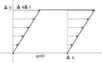
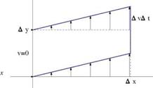
Consider a rectangular particle of initial size (Ax, Ay) near the wall y = 0. On the upper edge the velocity is u = Au. Equivalently, this corresponds to moving with a particle located at (0, 0) in a velocity field where v = 0. After a short time At the particle is sheared and takes the shape of a parallelogram. The strain rate is defined as є1і2 = limAy^0 Ay = &y. Similarly, considering a velocity field with u = 0 and upon superposition with the previous flow field, one finds the following strain rate, Fig.8.3

du dv

£1,2 = £2,1 = +

dy dx

(a) y

Vorticity Versus Strain Rate in 2-D

Fig. 8.3 Shear a in x-direction and b in ^-direction


(b) y


x


Further, we define the following strain rates

du. d v

£1,1 = 2— and £2,2 = 2— dx dy


(8.3)


Vorticity is defined as


du dv

d y + dx


(8.4)


and the angular velocity of the particle as


1 1 ( du dv

Q = w = — +

2 2 dy dx


(8.5)


A general deformation reads:


u(x + Ax, y + Ay, t) = u(x, y, t) + Au(x, y, t) +———–

v(x + Ax, y + Ay, t) = v(x, y, t) + Av(x, y, t) + •••


(8.6)


where


Au(x, y, t) = du Ax + Ц Ay + Av(x, y, t) = dvAx + dv Ay + ■


(8.7)


or, in matrix form


(8.8)


Vorticity Versus Strain Rate in 2-D

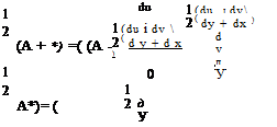
Note: any square matrix A can be decomposed uniquely into the sum of a sym­metric and antisymmetric matrices

Подпись: (8.9)A = 1 (A + A*) + 1 (A – A)

where A* is the transposed of A. Hence

Vorticity Versus Strain Rate in 2-D

1 / £1,1 ё 1,2

2 £1,2 £2,2

1 ( 0 – из

= 2 U 0


(8.10)


(8.11)


Vorticity Versus Strain Rate in 2-D

Vorticity Versus Strain Rate in 2-D

Therefore

u(x + Ax, y + Ay, t)
v(x + Ax, y + Ay, t)
general 2 – D motion

Vorticity Versus Strain Rate in 2-D

(8.12)


Vorticity Versus Strain Rate in 2-D

Viscous Fluid Flow and Laminar Boundary Layers

8.1 Incompressible 2-D Flows

Viscous stresses are important in studying aerodynamics and calculating the forces. So far, we have ignored the viscous stresses compared to the pressure and acceleration in the so called inviscid flow in the region outside the viscous layers (around the body and in the wake) (Fig. 8.1).

In the neighborhood of the solid surface, the flow slows down and the relative velocity is zero on the surface because of viscosity (no slip condition). The velocity profile u(y) is shown in the sketch, Fig.8.2. Note that in this chapter we will use a local coordinate system with x the curvilinear abscissa along the profile and y the normal distance to the wall, with unit vectors (i, j). Note also that the velocity components u and v represent the full velocity, not just the perturbations from the undisturbed flow.

Подпись: — A |wi and d y
Viscous Fluid Flow and Laminar Boundary Layers

The friction drag per unit span, Df is given by the shear stress т integrated over the area:

where a is the viscosity coefficient and tw is the component of the shear stress at

the wall in the direction of the incoming flow.

In general a is a function of temperature and slightly depends on pressure. It can be assumed constant for low and moderate speeds.

In our study, we will consider the flow to be laminar; transitional and turbulent flows are more complicated and little is known, in this regard, for practical applica­tions. Therefore, the Reynolds number, Re — in our study is limited. Laminar separated flows will be discussed, and the effect of pressure gradient (retarding the flow) leading to stall (less lift and more drag) will be emphasized.

© Springer Science+Business Media Dordrecht 2015 261

J. J. Chattot and M. M. Hafez, Theoretical and Applied Aerodynamics,

DOI 10.1007/978-94-017-9825-9_8

Viscous Fluid Flow and Laminar Boundary Layers

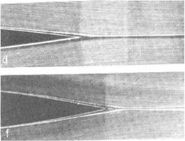
Fig. 8.1 Hydrodynamic visualization, courtesy H. Werle ONERA—the French Aerospace Lab, ONERA RA 1987-3


у


u x, у) ue (x)


Fig. 8.2


Viscous Fluid Flow and Laminar Boundary Layers

Summary of Chapter 7

First, the governing equations are derived in cylindrical coordinates. The full potential equation and the small disturbance theory are followed including calculations of wave drag and optimum shapes (due to von Karman and Sears and Haaks) for bodies of revolution in supersonic flows. Slender wings of low aspect ratios, including swept and oblique wings, wing-body combinations and slender bodies with general cross­sections are also discussed.

The transonic area rule, involving lift, as well as the supersonic area rule are briefly covered.

Finally, conical flows are studied using the full potential equation and small dis­turbance approximation, as well as numerical solution of the conical Euler equations.

7.9 Problems

7.11.1

According to slender body theory, the fuselage does not contribute to lift, but con­tributes to the pitching moment.

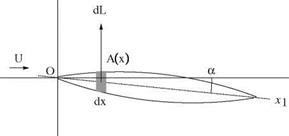
Show that the fuselage moment is given by (see Fig. 7.28)

M, of = pU 2 & f a

where, & f is the volume of the fuselage.

Summary of Chapter 7

z

Summary of Chapter 7

Fig. 7.28 Moment of a body of revolution at incidence

Summary of Chapter 7

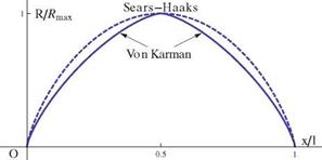
Fig. 7.29 Geometries of two pointed bodies

7.11.2

Consider two bodies pointed at both ends, the Sears-Haaks body and a body obtained by combining two Von Karman ogives (VK-KV), one facing forward and the other facing backward, see Fig. 7.29. The equation for the latter can be described as

S'(x) = 2l A^J(1 – 2х), 0 < x < 2
S'(x) = —2l A. J (2х – 1)(2 – 2х), 2 < x < i

corresponding to two elliptic distributions. Calculate the wave drag of the VK-KV configuration and compare to the Sears-Haaks body for the same maximum cross section. Hint: one approach is to calculate the Fourier coefficients in terms of A with a computer algebra system such as Mathematica to find the drag as

П12 “

ArefCow = – nA2„

n=1

In particular show that

1

A1 = 0, A2 = A, A3 = 0, A4 = — —, …

Rectangular Wings at Angle of Attack

Assuming small disturbances, the flow past a rectangular wing is two-dimensional except within the mach cones generated at the tips, where conical flow exists, Fig. 7.26.

For the region outside the Mach cone, a transformation similar to Chaplygin’s produces two-dimensional wave equation. The solutions in the hyperbolic and elliptic regions must be joined such that the velocity components are continuous across the Mach cone.

More complicated analysis includes, Prandtl-Meyer’s expansion, shock waves and formation of vortex flow.

7.9.2 Numerical Solution of Conical Euler Equations

The conservation laws in conical coordinates are given by (see Powell [33, 34]) r d U r д д d

КИТ + К2 dr (F + nG + ZH) + ^ (G – nF) + — (H – ZF) + 2F = 0

(7.167)

where

Подпись: (7.168)r = x2 + y2 + z2, n = , Z = , К = 1 + n2 + Z2

U, F, G and H are the standard state vector and flux vectors of the Euler equations in Cartesian coordinates.

The conical velocities are given by

uK = u + nv + Zw (7.169)

un = v — nu (7.170)

u z = w — Z u (7.171)

For conical flows, dU/dr = 0 and the boundary conditions must be consistent with conical flow assumption.

The governing equations become

к d

1

1 Ъ ____ 1

d

pun

puun — np

d

p u Z

puuz — ZP

pu

pu2 + p

Г d t

pv

+ dn

p uun + p

+ dZ

pvuZ

+ 2

puv

pw

pwun

pwuZ+p

puw

p E

p Hun

p Huz

puH

(7.172)

where H = E + р/р.

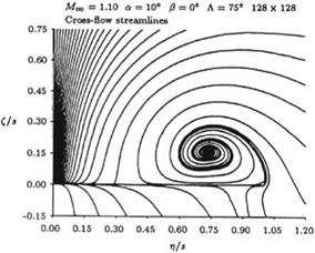
Based on topological considerations, Powell indicated that the physically mean­ingful singularities of conical flows are nodes, saddles and spirals.

Подпись: Fig. 7.27 Conical flow past a delta wing at incidence: cross-flow streamlines (with kind permission of the author, Prof. K. Powell)
Rectangular Wings at Angle of Attack

A cell vertex, finite volume, multi-stage Runge-Kutta scheme, with added artificial viscosity, was used to obtain numerical solutions over delta wings with grid gener­ation allowing multiple levels of refinement. Typical results are shown in Fig.7.27 (from Ref. [33, 34]).

The above study concluded that low pressure and density were seen in the vortex region.

Numerical parameters such as grid resolution and artificial viscosity did not affect the level of the total pressure loss, only the distribution of it. Modeling the core region remains however to be a problem.

In general, the conical flow calculation is less expensive than the full three­dimensional one. However, since the conical flow is supersonic everywhere, a space marching technique is an alternative. simply, artificial time is equivalent to a certain space marching and the latter is less restrictive.

Today, full three-dimensional Navier-Stokes solutions for high speed flows over delta wings are available, including simulation of important phenomena, for example vortex breakdown. CFD was an important tool in modifying the design of fighter jets where the vortex generated from the leading edge and its interaction with the tail was a serious problem.

Conical Flow Past a Delta Wing

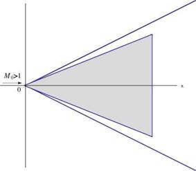
In general, in a conical flow, all fluid properties are invariant along rays through a common vertex. An example of such flows is a triangular wing in supersonic flow, where disturbances are propagated only in the downstream Mach cone. Notice conical flows are not possible in subsonic flow regime.

Following Shapiro [31] and Ashley and Landhal [1], the governing perturbation potential equation is given by

Conical Flow Past a Delta Wing

Conical Flow Past a Delta Wing

Fig. 7.25 Delta wing in supersonic flow


y


2 d2ф д2ф д2ф

M0)dX2 + – 0


(7.152)


(1


Conical Flow Past a Delta Wing

where the origin is placed at the vertex, and the free stream is in the x-direction, Fig. 7.25.

Подпись: a Подпись: в x Подпись: y2 + z2, Подпись: в — tan 1 Подпись: (7.153)
Conical Flow Past a Delta Wing

The velocity components (u, v, w) are also governed by similar equations. Following Hayes [27] and Stewart [32], conical coordinates are introduced where

The governing equation for the u-velocity component becomes (see also Ashley and Landhal [1])

Подпись: (7.154)2 д2U 1 2 дU 1 д2U

(1 – a 2)^ + a(1 – 2a V + a^ ^ — 0

In the (n, Z) plane. the Mach cone is represented by a unit circle and the wing by a slit along the n-axis of length 2д — в/tan Л, where Л is the sweep angle.

On the mach cone, u, v, w vanish and on the slit w — —a. Using Chaplygin’s transformation, where

Подпись: (7.155)1 — V1 — a2 d q 1 q

a ’ d a 1 — a 2 a

the above equation is reduced to the standard, two dimensional Laplace equation

Conical Flow Past a Delta Wing

Conical Flow Past a Delta Wing

The velocity components are related through the irrotationality conditions, hence on the slit

= 0, |nl < ml (7.158)

dZ

On the Mach cone

u = 0, on n = 0 (7.159)

Conical Flow Past a Delta Wing Подпись: (7.160)

From the incompressible flow solution for a flow normal to a plate, one expects that u has a square-root singularity at the leading edge. Indeed, for a delta wing with

where C is a real constant (since the boundary conditions are homogeneous).

Obviously, C ^ 1 as m’ ^ 0 to recover the slender body solution for a delta wing with vanishing span.

The determination of C (to satisfy the boundary condition w = – a) is compli­cated. Referring to Ashley and Landhal [1]

(7.161)

Conical Flow Past a Delta Wing Подпись: (7.162)

where E (k) is the complete elliptic integral of second kind with modulus k. The pressure coefficient is given by

Подпись: CL Подпись: n AR C ( 2 Подпись: (7.163)

The lift coefficient is found to be

The above results are consistent with slender body theory for m = 1 (or k = 1) and with supersonic edge theory for m = 1 (or k = 0).

The drag is given by

for supersonic edges. When the leading edge is subsonic, Jones and Cohen [11] accounted for leading edge suction, where

Подпись: (7.165)D = L a – Fs

Подпись: CD Conical Flow Past a Delta Wing Подпись: (7.166)

with their estimate of Fs

Small Disturbance Approximations for Flows Over a Cone

Von Karman and Moore [3] showed that the perturbation potential may be represented as an integral over a distribution of sources

Small Disturbance Approximations for Flows Over a Cone
Подпись: (7.137)
Подпись: ф(х, r) = -

where в = УM02 – 1. Following the presentation of Liepmann and Roshko [6], a change of variable is recommended from ф to a

ф = x – вг cosh a, ^ dф = – вг sinh ada = –/(x – ф)2 – в2r2da

(7.138)

Small Disturbance Approximations for Flows Over a Cone Small Disturbance Approximations for Flows Over a Cone

The integral and the limit of integration become

Notice, u and v are invariant along lines x|r = const. The solution can represent supersonic flow over a cone, where the vertex angle depends on a.

Small Disturbance Approximations for Flows Over a Cone Подпись: (7.142)

Applying the boundary condition

Подпись: Hence Small Disturbance Approximations for Flows Over a Cone Подпись: (7.144)

u = —a cosh 1 ^- v = a^Jcot2 8 – в2 (7.143)

For slender cones, with 8 ^ 1, and cot 8 > в, then

Подпись:Подпись: 0 as 8 ^ 0 (7.145)(cot8 ( 2

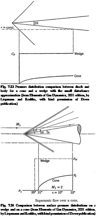
he pressure rise on the cone is much less than on the wedge, as shown in Fig. 7.23.

Notice the pressure is uniform over the surface, however the distribution of the pressure coefficient along a line r = const. rises continuously downstream of the shock. Also, in the slender body approximation, there is no pressure jump at the nose.

The accuracy of the slender body approximation can be numerically evaluated by comparison to the numerical results of Maccoll and the tables of Kopal. A typical case is shown in Fig. 7.24 (see Liepmann and Roshko [6]).