Category Theoretical and Applied Aerodynamics

Conical Flows

7.9.1 Method of Taylor and Maccoll

Consider supersonic flow over a cone at zero incidence, with a conical shock attached to the tip of the cone. The shock is of uniform strength and the entropy jump across the shock is also uniform, hence the flow between the shock and the cone is isentropic and irrotational. Unlike the two-dimensional wedge case, the corresponding governing equations are complicated. In the following, numerical integration due to Taylor and Maccoll [30] will be discussed.

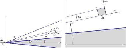
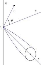
Assuming that all the fluid properties are constant on cones with common vertex at the tip of the cone, and using spherical coordinates, the equation of continuity, the definition of vorticity and Bernoulli’s law are given below (Shapiro [31]). Conser­vation of mass from control volume analysis, Fig.7.22, reads

Conical Flows

Fig. 7.22 Conical flow in meridian plane and control volume


Conical Flows

(7.130)


Since д/дг = 0, then д/дш = d/dш and the above equation becomes

Подпись:dum dp

2pur + рию cot ш + p + ию = 0

d ш d ш

Conical Flows
Irrotationality, Fig. 7.22, yields

Conical Flows
Conical Flows

— kur


ur — 0


V2


(7.135)


Conical FlowsConical Flows

Conical Flows

The integration of the above equation was first done by Busemann, using a graph­ical construction in the hodograph plane. Later, Taylor and Maccoll [30] used a straightforward numerical integration.

(i)

Подпись: ur Conical Flows Подпись: ua Conical Flows Подпись: at Подпись: (a)cone — Є Подпись: (7.136)

Begin with

(ii) Integrate the nonlinear O. D.E. stepwise, using small steps in a, by replacing the derivatives by finite differences.

(iii) After finding ur/ Vmax for each value of a, calculate ua/Vmax using the irrotationality condition in discrete form.

(iv) The final step is to find the shock angle в and the free stream velocity U/ Vmax. For each value of a during the integration, the downstream Mach number M of a shock with an angle в — a and turning angle в are compared with the value of M obtained from the integration process. If the two numbers agree, the limit of integration has been reached.

The incoming Mach number M0 can be found from the shock tables. The shock relations together with the isentropic relations for the conical flow region provide all the necessary information.

As in the wedge case, one may construct a shock polar in the hodograph plane.

For each value of M0 there exists a maximum value of the cone semi-angle e for which there is a solution to the conical flow equations, and vice-versa, for each value of e, there is a minimum M0. Also, for a given M0 and for e < emax, there are two solutions, with strong and weak shocks. Since the flow behind the strong shock is always subsonic, which cannot be conical, the strong shock is not possible and should be eliminated. On the other hand, the weak shock solution is possible with finite cones in supersonic flow because cutting off the downstream part of the cone cannot affect the upstream flow.

Notice for equal cone and wedge angles, the surface pressure rise and shock angle are smaller for cones due to the three dimensional effects.

Supersonic Area Rule

Hayes [27] derived a formula for the wave drag of a wing-body configuration of arbitrary thickness distribution and experiencing both lift and side forces.

For a thin non lifting wing, the source distribution is related to the geometry via (see Ashley and Landhal [1])

q(x, y) = _дд (7.123)

д x

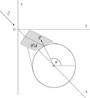
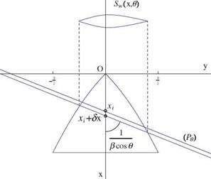
Consider the Mach planes passing through a point xi along the x-axis and tangent to the Mach cone with apex at xi, see Fig. 7.18. Let в be the angle of the normal to the plane with the y-axis. The equation of such a plane is (Pe ) : x — xi + вy cos в + вz sin в. The intersection of two parallel neighboring Mach planes with the (x, y)- plane is shown in Fig. 7.19. The intersection with the slender wing is projected on a plane normal to the axis as Sw(x, в), also shown in the figure. Then upon integrating in y and lumping the source along the x-axis, on finds

nr m f дg(xi + вy cos в, y)

Q(xi, в) = _ — dy

Supersonic Area Rule

д

д x


Sw (x, в)


(7.124)


_ g(xi + вy cos в, y)dy


Supersonic Area Rule

Fig. 7.18 Mach cone and Mach plane


Supersonic Area Rule

Fig. 7.19 Section of wing by characteristic plane (Pg)


Supersonic Area Rule

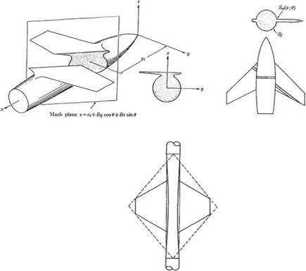
Fig. 7.20 Supersonic area rule methodology (from Aerodynamics of Wings and Body, by H. Ashley and M. Landhal, with kind permission of Dover Publication, 1985 edition)

For a body of revolution

Q(Xi) ~ Sf (xi) (7.125)

since, for a slender body, the area of the oblique cut will not differ much from its projection.

For a winged body of revolution, the area distribution of the equivalent body is

S(x,0) = Sf (x) + Sw(x ,0) (7.126)

Following Lomax and Heaslet [28], Fig. 7.20, the effect of wing-body interference can be represented through

Se (x) = Sf (x) + A0(x) (7.127)

where

1 r2n,

A0(x) = Sw(x, 0)d0 (7.128)

2n 0

Fig. 7.21 Flat plate lift induced by a body of revolution in supersonic flow

Supersonic Area RuleMinimum wave drag (for non lifting configuration) can be achieved by choosing Se (x) to be an optimum shape, i. e. the Sears-Haaks body. Thus the fuselage will be indented in the region of the wing.
If the body is approximated by an infinite cylinder, the optimum body indentation is then given by

A Sf + Ao(x) = 0 (7.129)

The above supersonic area rule includes the transonic area rule, in the limit of M0 ^ 1.

Jones [11, 12], considered the lifting case, including the vortex drag and concluded that the total drag would be minimized for elliptic loading. The three-dimensional drag for a straight elliptic wing will be always greater than the two-dimensional drag.

Lower values, however, can be obtained by yawing the wing behind the Mach cone.

The wave drag interference between lift and thickness is zero for a mid wing body. A favorable interaction is possible (see Ferri et al. [29]).

For a flat plate at zero angle of attack located above the body, a lift will be generated without drag, and the drag of the body will be lower due to the wave reflection from the wing impinging on the rear part of the body (Ashley andLandhal [1]), Fig.7.21.

Slender Bodies with General Cross Sections

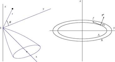
Consider a slender body, with a contour A at x location and contour B at x + dx, as shown in Fig. 7.16.

In the neighborhood of the body, the governing equation in terms of a small disturbance potential is the Laplace equation in the (y, z) cross plane

Slender Bodies with General Cross Sections

Fig. 7.16 Slender body with general cross section


д 2ф д2ф

0

дy2 дz2


(7.103)


The boundary condition requires the flow to be tangent to the surface


дф dn

~Z body = U —

д n dx


(7.104)


where n and t are in the normal and tangential directions of the contour of the cross section, respectively.

Applying Green’s theorem in two-dimensions, yields a particular solution


ф = 27/(77- фдп)ln rdl

where r = У(y – n)2 + (z – Z)2.

For large r, ф can be approximated by


(7.105)


1

ф = ln r


дф

dt д П


(7.106)


Slender Bodies with General Cross Sections

In this approximation, д In r is neglected compared to ln r and r — л/y2 + z2. From the boundary condition

dn dS

dt = U dx dx


Slender Bodies with General Cross Sections

where S(x) is the cross sectional area.

The general solution is then

Подпись: (7.109)

Подпись: Hence
Подпись: U , ф ~ S (x) ln r
Подпись: (7.108)

U

ф ~ S (x) ln r + g(x)

Подпись: = Slender Bodies with General Cross Sections Подпись: (7.110)

The pressure coefficient is

This is the same as the solution for an axisymmetric body having the same cross sectional area distribution as the actual body with a general cross section.

Oswatitsch andKeune [2], Ward [18-20] andAshley, andLandhal [1] were among the first who derived the equivalence rule for transonic, subsonic and supersonic flows: “Far away from a general slender body, the flow becomes axisymmetric and equal to the flow around the equivalent body of revolution.” “Near the slen­der body, the flow differs from that around the equivalent body of revolution by a two-dimensional constant-density cross flow part that makes the tangency condition at the body surface satisfied.” (See also Harder and Klunker [21], Guderley [22] and Cole and Cook [23]).

One can solve the axisymmetric small disturbance equation for transonic, sub­sonic or supersonic flows over the equivalent body of revolution to provide the far field boundary condition for a two-dimensional cross flow calculation at each cross section.

It can be shown that the pressure drag of the general slender body is equal to the drag of the equivalent body of revolution if the body ends in a point (S = 0) or in a cylindrical portion parallel to the free stream (S’ = 0 and ^ = 0). It is also true if the body ends with an axisymmetric portion.

Whitcomb [24] had verified these results experimentally, and the agreement was good in the transonic regime. Therefore, it is possible to reduce the wave drag of a wing-body combination by indenting the body such that the equivalent body of revolution has a smooth area distribution. This is the basis of “transonic area rule.”

Whitcomb has also shown experimentally that at high angle of attack, the lift contributes to the cross sectional area distribution of the equivalent body.

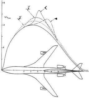
Cheng and Hafez [25], and Cheng [26], developed a theoretical justification in the transonic regime due to the nonlinearity of the governing equation, therefore in a good design, the fuselage will have a reduced waist at the location of the wing. See Fig. 7.17 for several arrangements.

Slender Bodies with General Cross Sections

Fig. 7.17 Equivalent-body cross-section area at Mach 0.98 (from Chap. 23 of Numerical and Physical Aspects of Aerodynamic Flows, Ed. T. Cebeci, published by Springer Verlag, 1982, with kind permission of Springer)


Basic to their study are the parameters


. b _ Smax Lmax

A = , t = , a =

l bl pU2bl


(7.111)


Slender Bodies with General Cross Sections

where ф and ф2 are governed by two-dimensional Laplace’s equations in y and z. For larger r


Ub


Slender Bodies with General Cross Sections

(7.113)


Slender Bodies with General Cross Sections

Slender Bodies with General Cross Sections

The above expression yields an axisymmetric flow as r ^ to, confirming the area rule.

However, if t is much smaller than a, the cross flow solution breaks down before the source distribution prevails over the doublet distribution. in this case, nonlinear effects near the wing are important. The fuller equation governing the perturbation potential near the wing is

Подпись: д2ф д2ф ду2 + д z2 Подпись: д2 ф д X 2
Подпись: 2 1 дф 1)+(y + 1)Mo2 U -£
Подпись: (M0
Подпись: (7.114)

The nonlinear terms on the right hand side act as a source term in the cross flow equation (hence the doublet distribution contributes to the source distribution).

Away from the body, the three-dimensional equation must be solved to fully account for these nonlinear effects, and the solution is determined principally by the doublet and the source distributions from the solution of the cross flow equation, including the nonlinear corrections.

The doublet distribution is still proportional to b2(x), as in linear theory, however the effective source distribution consists of two parts

dSe dS d (dD2

– = + a (7.115)

dx dx dx dx

The second term in the above expression is due to the nonlinear correction in the cross flow solution, where a is a parameter representing the relative importance of the lift.

Подпись: (1 - M2) Slender Bodies with General Cross Sections Подпись: д2 ф 1 д дф 1 д 2ф дx2 + Г дГ дг + Г2 дв2 Подпись: (7.116)

Now, one can solve the three dimensional small disturbance equation away from the body

Slender Bodies with General Cross Sections Подпись: то Подпись: (7.117)

with

and

Подпись:Подпись: asг дф 1 _ dSe 1 sin в

= т — a D(x)

Ub д г 2п dx 2п г

the solution of the above three dimensional problem provides the far field boundary conditions for the cross flow problems at each cross section, including the nonlinear effects as a forcing function and with the tangency condition at the solid surface. Notice iterations are needed to account for the forcing function.

Подпись: ф(x, г, в) Ub Slender Bodies with General Cross Sections Подпись: (7.119)

If lift effects are not dominant, the three dimensional problem can be split into two axisymmetric ones where

and ф0 and ф12 are governed by

Both ф0 ^ 0, and ф2 ^ 0 as г ^гх>, and as approaching the axis, we have

Подпись:

Slender Bodies with General Cross Sections
Подпись: (7.120)
Подпись: = 0
Подпись: (7.121)

г дф0 1 _ dSe r2 дфі2

Ub дr 2n dx’ Ub дr

Special treatment is required to enforce the perturbed shock jump condition for ф12 problem.

For more details, the reader is referred to Cheng and Hafez [25], particularly for the estimate of the size of the region in the neighborhood of the body, which is obtained via asymptotic analysis.

Swept and Oblique Wings

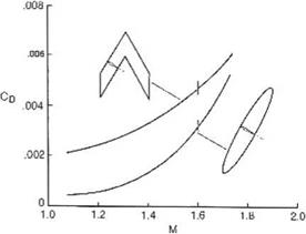
For high speeds, swept wings are used since the velocity component normal to the leading edge determines the aerodynamic performance of the wing. R. T. Jones [11, 12] claims, based on theoretical and experimental results, that oblique wings are better, see Fig. 7.11.

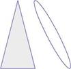
Comparison with a delta wing is also shown in Fig. 7.12.

Jones used Kogan’s theory [13] to determine minimum drag of elliptic wings. For details, see Ref. [11].

7.3 Wing-Body Combinations

A body of revolution, carrying plane wings of small aspect ratio can be analyzed using the results of the previous sections, via the Joukowski transformation. Consider a mid-winged body of revolution as in Fig.7.13.

Подпись: Fig. 7.11 Comparison of oblique and sweptback wings
Swept and Oblique Wings

For the calculation of the lift, we will follow Spreiter [14], who solved the cross flow problem by mapping the cylinder onto the Y-axis using

Подпись: CdПодпись:Подпись: CdПодпись: ‘-= 0.3Swept and Oblique WingsFig. 7.12 Drag due to lift: oblique elliptic wing and delta wing, M = 2

Swept and Oblique Wings

Fig. 7.13 Wing-body combination


Z


-2R


2R

_i_


Y


O


Swept and Oblique Wings

Usina

Fig. 7.14 Mapping of wing-body cross section onto the Y coordinate axis

Swept and Oblique Wings

(7.98)


The wings map also onto the Y-axis and the wing edges are located at Y = ±2(1 + b2) = Fig. 7.14.

The problem of the flow normal to a flat plate has been discussed before (the flow over a flat plate is related to a flow over a cylinder).

It should be mentioned that the two-dimensional cross flow solution is unrealistic, since the flow will separate at the plate edges. With a three-dimensional slender wing-body configuration, the axial flow keeps the cross flow from separating so the potential solution is a good approximation, for small angles of attack.

Spreiter [14] obtained the following result for the lift (see also Ashley and Landhal [1]):

2/b2 2 4R4

L = npU2 4 – R2 + 42 a (7.99)

Special cases of the body alone or the wing alone are included in this formula. To estimate the effect of the fuselage on total lift, i. e. body interference, consider the ratio

Swept and Oblique WingsLw+b Lw

y


x


Swept and Oblique Wings

(7.101)


Swept and Oblique WingsSwept and Oblique Wings

Swept and Oblique Wings

where D0 is the wave drag at zero incidence.

Подпись:The drag for subsonic flow reduces to induced drag R = 0, it becomes

Подпись: n 2 b2 2 D = pU2 a 2P 4

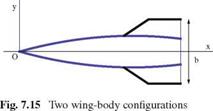
The above formulas are valid for two types of configurations: a body of revolution having general cross section with wings whose edges are everywhere leading edges, and for a body of revolution with a uniform cross section downstream from the section of maximum wing span, as shown in the following sketches, Fig. 7.15.

For the case of an uncambered wing with swept-forward trailing edges, the lift on sections behind that of maximum span is zero in the present approximation and b is replaced by bmax in the above formulas.

In the case of swept-back trailing edges, as for an arrowhead wing, the analysis requires the solution of hyper integral equations (seeMangler [15]). See also Brandao [16].

For supersonic flows past bodies of revolution, when S’ (x) is discontinuous, the reader is referred to the work of Lighthill [17].

For ducted bodies of revolution with annular intakes, see Ward [18-20].

Low Aspect Ratio Flat Wings

Подпись: дф д y Low Aspect Ratio Flat Wings Подпись: ^2U a Подпись: 2У b Подпись: дф —— = 0 Подпись: (7.83)

The cross flow over a flat plate is known from Chap. 2, Eq. (2.84), and with the current coordinate system and notation, the velocity components on the plate, in terms of the perturbation potential, are (see Katz and Plotkin [8], Duncan et al. [9])

Low Aspect Ratio Flat Wings Low Aspect Ratio Flat Wings Подпись: (7.84)

where b(x) is the wing span, the plus sign is for the lower surface, see Fig.7.10. Since дu/дy = дv/—x, one can find u by integration of дu/дy

From the Bernoulli equation, the pressure jump at a point (x, y, 0) of the wing is given by Ap = p(x, y, 0-) – p(x, y, 0+). This reduces to

Low Aspect Ratio Flat WingsFig. 7.10 Low aspect ratio flat wing
Low Aspect Ratio Flat Wings

Low Aspect Ratio Flat Wings

(7.85)


A section of the wing of length dx will contribute a lift force dL as


Low Aspect Ratio Flat Wings

where we have made the change of variables y = —§ cos t, 0 < t < n. The result reads

n 2 db

dL = – pU2 ab dx (7.87)

2 dx

Upon integration in x, the partial lift force, from x = 0 to x becomes


L (x) = ^pU 2b2 a


(7.88)


For the whole wing, L = ПpU2b2(c)a. Let Aref be the wing projected area, then the lift coefficient can be written as


n AR

Cl = —a


(7.89)


The и-component provides, upon integration, the perturbation potential


Low Aspect Ratio Flat Wings

(7.90)


Low Aspect Ratio Flat Wings

Since ф is an odd function of z and ф is continuous at the wing edge, f (x) = 0. The jump of ф is the circulation f(x, y), hence

Low Aspect Ratio Flat Wings

(7.91)


The slender flat wing has elliptic loading. The induced drag is therefore given by the same formula as for a large aspect ratio wing, i. e.

CL nAR 2

CDi = ^ = a2

n AR 4

The induced incidence at is such that CDi = —CLat. One finds at = – a/2. The resulting force due to pressure is not perpendicular to the flat wing, as would be expected, because as in thin airfoil theory, the wing edge experiences a suction force due to the infinite velocity and vacuum pressure at the sharp edge. The force is in the z = 0 plane and its x-component is equal to Fs = —La/2. Note that the suction force does not exist if the leading edge is supersonic.

For triangular wings, the loading is constant along any straight line through the vertex (i. e. conical flow), the angle t with the x-axis being constant along such a line

Подпись: since sin t = У1 — (IT) = const.

The pitching moment about the у-axis is given by

Low Aspect Ratio Flat Wings

(7.94)


Low Aspect Ratio Flat Wings

The pitching moment is made dimensionless with the wing area and the chord as

Подпись: (7.95)n AR

Cm, o = 3— a

The center of pressure, as well as the aerodynamic center, for the flat plate wing are found to be located at

Подпись:(7.96)

Finally, between the body of revolution and the flat wing, one can think of wings with elliptic cross sections. The flat plate cross section is the limiting case of the ellipse.

The order of magnitude for the lift coefficient in this section is consistent with the lifting line theory for elliptic loading of small aspect ratio wings, where CL is proportional to n ARa, and independent of M0.

Following Weissinger [10], the low and high aspect ratio wing formulae are com­bined in a single expression for extended lifting line theory and after applying the Prandtl/Glauert rule, yielding

^ AR

Ve2 AR2 + 4 + 2

Lift and Induced Drag of a Body of Revolution at Angle of Attack

Подпись: 2 д2ф 1 d M0 ^ + 7 dr Подпись: 1д2ф + Г2 ^2 = 0
Lift and Induced Drag of a Body of Revolution at Angle of Attack

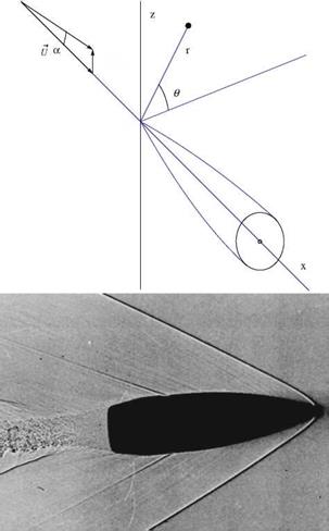
The flow situation is depicted in Fig.7.8. The perturbation potential ф is governed in this case by the three dimensional equation

y


Usin a


Ucos a


Lift and Induced Drag of a Body of Revolution at Angle of Attack

0

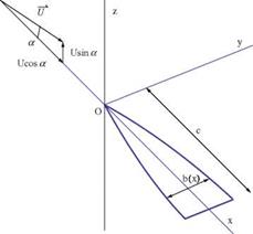
Fig. 7.8 Body of revolution at angle of attack: Top, coordinate system; Bottom, bullet at supersonic speed (from http://en. wikipedia. org)

The boundary condition is given by

Подпись:ur dR

ux body dx

In terms of the incoming flow and perturbation velocity, this becomes

U sin a sin в + ^r dR

V U cos a + Ш )body ~ d

Because of linearity, ф can be written as (see Liepmann and Roshko [6])

Lift and Induced Drag of a Body of Revolution at Angle of Attack Lift and Induced Drag of a Body of Revolution at Angle of Attack

ф(х, r, в) = ф0 (x, r) + фа(х, r, в) (7.64)

and фа is solution of the full equation that can be modeled as a doublet distribution along the x-axis. The axis of the doublet is parallel to the z-axis to represent the cross flow, namely

дф0 дф0

фа (x, Г, в ) = 0 = sin в 0 (7.66)

Подпись: dR дфа дфа dx dx d r body Подпись: U sin a sin в Подпись: (7.67)

with the boundary condition on the surface as

This last equation is obtained to second-order O (a2) from the general boundary condition for ф, upon subtraction of the axisymmetric boundary condition for ф0.

Notice that the first term in the left-hand-side is very small for slender configura­tions. In this case

фа = ^X^ sin в (7.68)

r

Подпись: фа Lift and Induced Drag of a Body of Revolution at Angle of Attack Lift and Induced Drag of a Body of Revolution at Angle of Attack Подпись: (7.69)

The strength of the doublet q (x) is proportional to the cross sectional area

Therefore, the cross flow solution at any section is the same as the incompressible flow solution over a cylinder, independent of M0.

The surface pressure coefficient is given by

Подпись:2 1 Г / дф2 /1 дф 21

Подпись: hence Lift and Induced Drag of a Body of Revolution at Angle of Attack Подпись: / dR dx Подпись: (7.71)

U cos ad x (U cos a)2 dr r дв

and


Lift and Induced Drag of a Body of Revolution at Angle of Attack

(7.72)


Lift and Induced Drag of a Body of Revolution at Angle of Attack

In the latter expression, a2 terms are neglected.

The normal force in the z-direction can be calculated via integration

N = – p0U2 / f {—Cp, a sin в) Rdedx

2 0 0

1 2 I I 2 dR 1 2

= 4a-p0U2 sin2 в R de dx = 2a-p0U2 S(l) (7.73)

2 0 0 dx 2

Hence, the normal force coefficient, using the base area as reference, is given by

Cn = 2a (7.74)

Notice that, if the body is closed at both ends, N = 0.

The calculation of the drag is more delicate, since it is a small quantity (of order a2). For slender bodies, CL — CN = 2a, independent of M0, and the lift slope is dCL/da = 2 for incompressible and compressible flows.

If one considers a cross section of the body at a given x location and let the circulation be defined on the body as

r(x, в) = ивRde, 0 < в < п (7.75)

—в

then

r(x, в) = фa(x, R, в) — фa(x, R, —в)

= 2фa(x, R, в) = 2U sin aR(x) sin в = 2U sin a^JR2(x) — y2 (7.76)

In term of the “span” variable y, this is an elliptic loading with induced drag Coi = at Cl.

It can be shown that at = a/2 and CDi = a2.

Подпись: ArefCot = U 2 + 2 £base U' ^U ' Подпись: dydz Подпись: (7.77)

According to Viviand [7], the induced drag coefficient is given by the same formula as for a finite wing

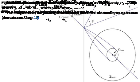
where the surface integral is performed on £base, the part of the cross flow plane outside the base of the body and approximately perpendicular to the incoming flow, Fig.7.9.

Lift and Induced Drag of a Body of Revolution at Angle of Attack
As seen in Chap. 6, this surface integral can be reduced to a line integral along the body base, Chase, as

Axisymmetric Flows and Slender Body Theories

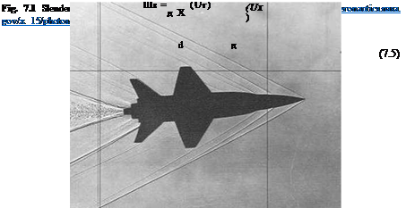
Axisymmetric flows are needed to analyze flow over bodies of revolution. Extensions to bodies of revolution with fins (missiles) or slender wings (low aspect ratio) are also possible, using perturbations of axisymmetric flows. In this chapter, it is natural to use cylindrical coordinates. After the derivation of the governing equations at different Mach number regimes (subsonic, supersonic, transonic), lift and drag are calculated for standard shapes (Fig. 7.1).

7.1 Governing Equations in Cylindrical Coordinates

Assuming steady, inviscid, adiabatic, irrotational and isentropic flow with uniform upstream conditions, the governing equations, in vector notation, are

V.(pV) = 0, VxV = to = 0 (7.1)

In cylindrical coordinates, Fig. 7.2, the conservation of mass is

Подпись: d 1 d 1 d

(p Ux) + (prur) + (pue) = 0 (7.2)

dx r dr r 89

where (ux, ur, u9 ) are the velocity components in x, r and 9-directions, respectively. The vorticity components are

1 d 1 d

Mx = (rue) – (ur) (7.3)

r dr r d9

1 d d

Mr = (ux) – (u9) (7.4)

r d9 dx

© Springer Science+Business Media Dordrecht 2015

J. J. Chattot and M. M. Hafez, Theoretical and Applied Aerodynamics,

DOI 10.1007/978-94-017-9825-9_7

Notice that Vм = 0, since м = Vx V. The condition is a consequence of the vector identity: the divergence of a curl vanishes.

The density can be calculated from Bernoulli’s law, assuming isentropic conditions

Подпись: P_ Po Axisymmetric Flows and Slender Body Theories(7.6)

Axisymmetric Flows and Slender Body Theories

Axisymmetric Flows and Slender Body Theories

Fig. 7.2 Slender body of revolution and coordinate system

and

Y p V2

+ = H0 = const. (7.7)

Y – 1 P 2

In the latter equation of isoenergetic flow, the potential energy is assumed constant (and does not appear in the total energy).

Подпись: P_ P0 Подпись: (1 - ^M2(V2 Подпись: (7.8)
Axisymmetric Flows and Slender Body Theories

From the above two equations, one obtains

For the irrotational flow, the velocity can be described by the gradient of a potential function

Подпись:Подпись: (7.9)V = VФ

Axisymmetric Flows and Slender Body Theories Axisymmetric Flows and Slender Body Theories Подпись: (7.10)
Axisymmetric Flows and Slender Body Theories

The potential equation in cylindrical coordinates is given by

The tangency boundary condition on a solid surface is VФ. п = 0, where n is the unit vector normal to the surface. Together with the far field condition, Ф ^ 0, as x2 + r2 ^ to, the formulation is complete.

Axisymmetric Flows and Slender Body Theories Axisymmetric Flows and Slender Body Theories

For a body of revolution at zero angle of attack, there is no dependency on в, and the governing equation reduces to

or

Подпись: (7.13)гдФ _ дФ dR _ 1 дФ dS дг дx dx 2п дx dx

Axisymmetric Flows and Slender Body Theories Подпись: (7.14)

where S(x) = п R2(x), is the cross-sectional area of the body. The pressure coefficient is

Axisymmetric Flows and Slender Body Theories
and

respectively. Also, the pressure coefficient becomes

(7.21)

Подпись: 2 дф Cp = ф p U д x Axisymmetric Flows and Slender Body TheoriesNote that, for body of revolution, д/дв = 0, and the last term in the above equations vanishes.

For incompressible flows (M0 = 0), the fundamental solution of the Laplace equation is

Подпись: (7.22)1 1

4n Vx2 + r2

Подпись: ф.ч Подпись: 1 1 4п |lx2 + e2r2 Подпись: в2 = 1 - M02 Подпись: (7.23)

For subsonic flows (M0 < 1), using the Prandtl-Glauert transformation, the fun­damental solution becomes

Подпись: ф Подпись: 1 4n Axisymmetric Flows and Slender Body Theories Подпись: (7.24)

For a source distribution q(x) per unit length along the x-axis, the perturbation potential at a point (x, r) reads

Подпись: дф lim rur = lim r r^0 r^0 д r Axisymmetric Flows and Slender Body Theories Подпись: (7.25)

The strength of the sources is determined through imposing the boundary condition

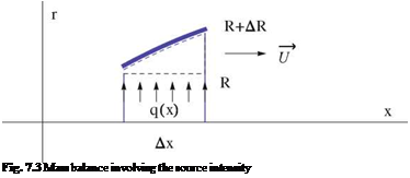
where S(x) = n R2(x) represents the cross section of the body of revolution. Notice from mass balance, one obtains (see Fig. 7.3)

Подпись: Fig. 7.3 Mass balance involving the source intensity

q(x)Ax = 2nRAR U = UAS (7.26)

Подпись: and Подпись: Ф Axisymmetric Flows and Slender Body Theories Axisymmetric Flows and Slender Body Theories

hence

Also, integrating the tangency condition in the proximity of the x-axis (small r)

дф U, U ,

r = S'(x), ^ ф ~ S(x) ln r + g(x) (7.29)

д r 2n 2n

Подпись: g(x) Подпись: U S (x) ln Подпись: S'(§) |x Axisymmetric Flows and Slender Body Theories Подпись: (7.30)
Axisymmetric Flows and Slender Body Theories

Oswatitsch and Keune [2] provided an approximation of the singular integral leading to

Note that the term g(x) depends in general on M0. For a body with a pointed nose and ending at a point or as a cylinder (S'(l) = 0)

U. (в U fx,, U fl,,

g(x) ~ 2ПS'(x) ln 2 – __ s"(§) ln(x -§)d§ + — S (§) ln(§ – x)d§

0 x (7.31)

Подпись: Фз Подпись: 1 1 2n л/x2 - в2r2 Подпись: в2 = M2 - 1 Подпись: (7.32)

For supersonic flow (M0 > 1), the fundamental solution is different. The solution for a supersonic source is

Подпись: Ф Подпись: 1 г--в ssjm m 2n 0 y/(x - §)2 - в2r2 Подпись: (7.33)

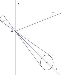
The potential is a real number only within the Mach cone, Fig. 7.4. A source distribution will give the solution

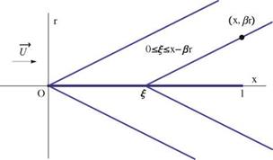
where the integral is evaluated only for values of § < x – вr, Fig. 7.5.

Von Karman and Moore [3] analyzed this singular integral. Their results are given by

Axisymmetric Flows and Slender Body Theories

и


Fig. 7.4 Mach cone


Axisymmetric Flows and Slender Body Theories

Fig. 7.5 Traces of Mach cones in meridian plane


U fx S'(£) – S(x)d£ 2n J0 x – £ £


U, U, в

S (x) ln t + S (x)

2n 2n 2x


(7.34)


Ф


Thus, for supersonic flows


Axisymmetric Flows and Slender Body Theories

U

2n


(7.35)


g(x)


Axisymmetric Flows and Slender Body Theories

Analysis Problem

Consider a wing with elliptic planform, of span b and chord c(y) = c0A/1 – (2 y/b)2. The wing has constant relative camber d(y)/c(y) = d/c = const and has washout given by t(y) = -4tx(2y/b)2, where -4tx is the twist at the wing tips.

Calculate the coefficients A1, A2,… ,An, n = 1, to. Hint: Write Prandtl integro – differential equation, where the circulation in the l. h.s. is represented by the Fourier series, and the wing geometry is introduced in the r. h.s. Use the change of variables y = -§ cos t, 0 < t < n and the identity 4cos21 sin t = sin t + sin 3t.

From the equation for A1 give the equation of the lift curve CL(a). What is the incidence of zero lift, a0?

Calculate the induced drag if a = 3tx – 2d/c.

6.14.1 Design Problem

Considering the lifting problem, design a rectangular wing of span b and chord c, (AR = b/c), with zero twist, and equipped with parabolic thin airfoils, such that the circulation is elliptic at the given lift coefficient CL, des = 0.5. Furthermore, at the design CL, des the wing has an adapted leading edge.

Find the relative camber distribution d(y)/c that will satisfy all the requirements. Where is the maximum camber located along the wing span? Calculate the value of the maximum camber.

Give the value of the geometric incidence at design, a, in terms of CL, des and AR. Show that at a different incidence, в = a, the circulation is no longer elliptic.

If viscous effects limit the maximum local lift coefficient to a value Ci, moa, which is the same for all profiles, where will stall occur first on the wing?

References

1. Viviand, H.: Ailes et Corps Elances en Theorie des petites Perturbations, Ecole Nationale Superieure de L’Aeronautique et de l’Espace: Premiere Partie, Class Notes (1972)

2. Prandtl, L.: Applications of Modern Hydrodynamics to Aeronautics. NACA, report 116 (1922)

3. Glauert, H.: The Elements of Aerofoil and Airscrew Theory. Cambridge University Press, Cambridge (1926)

4. Munk, M. M.: The Minimum Induced Drag of Aerofoils. NACA, Report 121 (1921)

5. Chattot, J.-J.: Low speed design and analysis of wing/winglet combinations including viscous effects. J. Aircr. 43(2), 386-389 (2006)

6. Chattot, J.-J.: Analysis and design of wings and wing/winglet combinations at low speeds. Comput. Fluid Dyn. J. 13(3), 597-604 (2006)

7. Ashley, H., Landhal, H.: Aerodynamics of Wings and Bodies. Addison Wesley Longman, Reading (1965)

8. Batchelor, G. K.: An Introduction to Fluid Dynamics. Cambridge University Press, New York (1967)

9. Moran, J.: An Introduction to Theoretical and Computational Aerodynamics. Wiley, New York (1984)

10. Weissinger, J.: NASA TM 1120 (1947)

11. Liepmann, H. W., Roshko, A.: Elements of Gas Dynamics. Wiley, New York (1957)

12. Nixon, D., Hancock, G. J.: Integral equation methods—a reappraisal. Symposium Transson – icum II. Springer, New York (1976)

13. Tseng, K., Morino, L.: Nonlinear Green’s function method for unsteady transonic flows. Tran­sonic Aerodynamics. Progress in Aeronautics and Astronautics, vol. 81. AIAA, New York (1982)

14. Garrick, I. E.: Non steady wing characteristics. Aerodynamic Components of Aircraft at High Speed. Princeton University Press, Princeton (1957)

15. Evvard, J. C.: Use of Source Distributions for Evaluating Theoretical Aerodynamics of Thin Finite Wings at Supersonic Speeds. NACA, Report 951 (1950)

16. Puckett, A. E., Stewart, H. J.: Aerodynamic performance of delta wings at supersonic speeds. J. Aerosp. Sci. 14, 567-578 (1947)

17. Klunker, E. B.: Contribution to Methods for Calculating the Flow About Thin Wings at Tran­sonic Speeds—Analytic Expression for the Far Field. NACA TN D-6530 (1971)

18. Cole, J. D., Cook, P.: Transonic Aerodynamics. North Holland, Amsterdam (1986)

19. Cheng, H. K., Meng, S. Y.: The oblique wing as a lifting-line problem in transonic flow. J. Fluid Mech. 97, 531-556 (1980)

20. Hafez, M.: Perturbation of transonic flow with shocks. Numerical and Physical Aspects of Aerodynamic Flows. Springer, New York (1982)

21. Jameson, A.: Transonic potential flow calculations using conservative form. In: Proceedings of 2nd AIAA CFD Conference (1975)

22. Caughey, D., Jameson, A.: Basic advances in the finite volume method for transonic potential flow calculations. Numerical and Physical Aspects of Aerodynamic Flows. Springer, New York (1982)

23. Holst, T., Thomas, S. D.: Numerical solution of transonic wing flow field. AIAA paper 82-0105 (1982)

24. Hafez, M., South, J., Murman, E.: Artificial compressibility methods forthe numerical solution of the full potential equation. AIAA J. 16, 573 (1978)

25. Hafez, M., Osher, S., Whitlow, W.: Improved finite difference schemes for transonic potential calculations. AIAA paper 84-0092 (1984)

Summary of Chapter 6

In this chapter, inviscid incompressible and compressible flows past large and moder­ate aspect ratio wings are studied. Thin wings that only slightly disturb an otherwise uniform flow are defined. The three-dimensional potential flow equation governs the flow. The tangency condition is a mere extension of the two-dimensional one and the linearized pressure coefficient still reads Cp = —2u/U.

First the linear theories are considered and the admissible jump conditions inves­tigated. It is shown that two types of discontinuities can occur, shock waves across which the pressure has a jump, i. e. < Cp >= 0 hence < u >= 0, and vortex sheets across which the pressure is continuous, i. e. < Cp >= 0 hence < u >= 0, and < w >= 0, but < v >= 0. In contrast with two-dimensional flow and its bound vorticity, three-dimensional flow combines bound vorticity in the finite wing and trailed vorticity in the vortex sheet. Forces and moments can be obtained from a momentum balance applied to a large control volume surrounding the finite wing. The formula for lift and pitching moment are consistent with the Kutta-Joukowski lift theorem applied to the bound vortex, whereas the drag exhibits two contributions, one corresponding to the wave drag, the other to the vortex drag or lift induced drag resulting from the trailed vortices.

For large aspect ratio wings, Prandtl lifting line theory is presented and the forces expressed as integrals along the span or lifting line. The matching between the local two-dimensional flow in a wing cross section and the three-dimensional flow super­imposed by the vortex sheet, which determines the local downwash and induced incidence, results in the celebrated integro-differential equation of Prandtl. The gen­eral solution of the latter can be sought as an infinite Fourier series with unknown coefficients for the Fourier modes. Lift and drag are found to be related to the Fourier coefficients in a remarkable way, the lift depending on the first mode only and the induced drag on a summation with positive weights of the squares of the coefficients in the series. This leads to the ideal wing having minimum drag for a given lift and corresponding to the first mode only. The circulation is elliptical and the downwash constant. The geometry of the ideal wing is not unique. In fact, in inviscid flow, there is an infinite number of wings that can produce the ideal loading. They differ by chord and twist distributions. Examples are shown of an elliptic planform without twist and a rectangular planform with twist that satisfy the requirement. Extension to non-straight lifting lines is also discussed and the design and analysis of winglets presented. For wings of arbitrary planform, the numerical simulation is the most practical approach and illustrated with the two examples above of ideal loading. The simulation includes also viscous effects and nonlinear profile polars, with a penalization technique to capture separated flow regions on the wing.

The vortex lattice method is described for flow past moderate aspect ratio wings. It is a natural extension of the lifting line method that has close connection with the treatment of unsteady flow past wings and wind turbines (see Chap. 10).

Compressible flow over moderate aspect ratio wings based on small disturbance approximations, in both subsonic and supersonic regimes, are treated with linearized boundary conditions. General wings in subsonic flows are treated based on Green’s theorems, while for general wings in supersonic flows, Kirchoff’s formula is used. For wings in transonic flows, full potential equations should be solved numerically. For high aspect ratio wings, transonic lifting line theory is briefly discussed.

6.13 Problems

Transonic Lifting Line Theory

Cole and Cook [18], and Cheng and Meng [19], extended classical lifting line theory to unswept and swept wings in transonic flows.

Подпись: ai(y) Подпись: (6.167)

For unswept wings in incompressible flows, Prandtl derived a single singular integral equation to account for the three-dimensional effects for large but finite aspect ratio wings. At each wing section, the two-dimensional theory can be used with an effective angle of attack, aeff = a – ai, where

The local two-dimensional theory can be replaced by numerical calculations, including viscous effects as discussed before this chapter.

To account for 3-D compressibility effects, an iterative method can be adopted as follows:

(i) First, the strip theory is used to calculate the circulation Г(y),

(ii) Secondly, the induced angle of attack is calculated numerically from the Prandtl singular integral equation, modified by Prandtl-Glauert’s transformation for subsonic far field,

(iii) The local two-dimensional transonic flow calculations with effective angle of attack, at each spanwise location y, are performed independently,

(iv) The process is repeated until convergence.

According to Prandtl’s theory, the downwash and the induced angle of attack are uniform across the span for an elliptic planform (without twist). In this case, thanks to similarity, only one section needs to be calculated.

In Hafez [20], numerical calculations confirm this result for both subsonic and transonic flows. The effective angle of attack is given by

aeff = a2D eAR + 2 ’ в =УІ1 – M0 (6Л68)

The corresponding formulas for the lift slope are dCL AR

— = 2эт^ + 2 (incompressible) (6.169)

Подпись: (6.170)dCL 2n pAR

= (subsonic)

Подпись: dCL d a Подпись: dCi pAR d a 2D @AR + 2 Подпись: (transonic) Подпись: (6.171)

da p pAR + 2

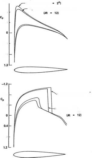
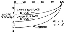
The following results of Ref. [20], confirm the validity of the above formula. The pressure distributions at the midspan for an elliptic planform (AR = 12) for M0 = 0.85 and a = 2°, are plotted for 2-D, corrected 2-D and 3-D calculations. The latter two sets are indistinguishable, see Fig. 6.40.

For the transonic case, the shock locus of 3-D flows for both upper and lower surfaces are plotted showing elliptic distributions, Fig.6.41.

The three calculations are produced from NASA full potential codes.

Transonic Lifting Line Theory Подпись: (6.172)

The transonic small disturbance theory for 3-D is based on the von Karman – Guderley equation

where ф is the dimensionless perturbation potential.

Transonic Lifting Line Theory2D SOLUTION (a

Подпись: -1.2 t-

Transonic Lifting Line Theory Подпись: -0.8 -

Подпись:

Подпись: -0.4 Transonic Lifting Line Theory

3D, CORRECTED 2D SOLUTIONS

0.8 –

Fig. 6.40 Top Surface pressure distributions at mid-span, M0 = 0; Bottom Surface pressure distri­butions at mid-span, M0 = 0.85

The linearized boundary condition is

Подпись: (f xy) - “)Подпись: (6.173)w(x, y, 0±) дф

U

where f ± (x, y ) represents the upper and lower wing surface coordinate. In the far-fleld, the potential vanishes.

Across the wake there is a jump in potential to guaranty the continuity of pressure, ignoring the vortex sheet roll-up.

The lift is given by integration of surface pressure which reduces to the integration along the lifting line, of the circulation

b xe 2 b

ArefCL = f2 dy f (Cp(x, y, 0-) – Cp(x, y, 0+)) dx = – 2 r(y)dy

– 2 хЫ U – 2

(6.174)

As x ^ to, the potential equation reduces in the Trefftz plane to

Подпись: (6.175)Подпись: dy2 + dz2 ^

Transonic Lifting Line Theory

д2ф d2ф

Across the vortex sheet, there is a jump in v = U Щ corresponding to the vortex strength Г'(y) = U < v >.

Transonic Lifting Line Theory Подпись: dydz - й dydz (6.176) 2 shocks ' u '

The drag is given by the integration in the Trefftz plane, where u = U Щ = 0 and on the shock surfaces. Cole and Cook [18] showed that

The first term is a non-recoverable kinetic energy in the Trefftz plane representing induced drag. The second term is the wave drag evaluated in terms of “entropy” production at shock surfaces, which would have been produced if the nonisentropic shock jump conditions were enforced.

For given lift, elliptic loading is optimal, provided shocks are not strengthened.

Cheng andMeng [19] analyzed oblique wings using swept lifting line and analogy of 3-D formulation and unsteady two-dimensional flows.

For practical applications, the full potential equation, with exact boundary condi­tions, is solved numerically. Artificial viscosity is needed in the supersonic regions for numerical stability and to prevent the formation of expansion shocks as shown by Jameson [21], Caughey [22] Holst and Thomas [23] and Hafez et al. [24, 25]. The latter are admitted by the potential equation based on isentropic relation.