Category Theoretical and Applied Aerodynamics

Wings in Transonic Flows

Wings in Transonic Flows Подпись: (6.162)

The governing equations in the transonic regime are nonlinear and of mixed type, to represent both locally subsonic and locally supersonic flow regions. The full potential equation is given by

where p is obtained via Bernoulli’s law in terms of V2 = (Vф)2. Together with the tangency boundary condition on a solid surface and imposing the right behavior of ф in the far field, the formulation is complete. Again, a special treatment is required to handle the wake, where ф is discontinuous.

The far field behavior, for subsonic incoming Mach number, is given by Klunker. Following Klunker, the integral equation for ф is analyzed to obtain the far field solution. The governing equation for Ыж < 1 can be written in the form

(6.163)

Подпись: Ф Подпись: 1 1 4n /(x - X1)2 + p2(y - У1)2 + e2(z - Z1 )2 Подпись: (6.164)

where ф is the perturbation potential. Using

Подпись: Ф = Подпись: (6.165)

Green’s second identity leads to

Wings in Transonic Flows

Asymptotically, ф behaves as a doublet in 3-D and a horseshoe distribution over the wing, see Klunker [17].

+———————————————————– 3-D (6.166)

4n [((x – ф)2 + P2(y – q)2 + P2(z – C)2)]2 where Г = (1ф-(, andD = f f f# M2^ (дф) d^dndC,-Wingvolume.

Wings in Supersonic Flows

The nature of supersonic flow is different from the subsonic one. The governing equations are hyperbolic, rather than elliptic, representing wave propagation. In two

Wings in Supersonic Flows
dimensional flows, the linearized small disturbance equation admits the d’Alembert solution (which is a special case of the method of characteristics). The corresponding solution of the three dimensional supersonic flow is based on Kirchoff’s formula, used for example in acoustics, see Garrick [14]. It is given by

Interchanging ф and ф and subtracting yields

Подпись:Подпись: (6.159)(фЬ(ф) — фЬ(ф)’) d9

if Ь(ф) = 0 and Ь(ф) = 0, we obtain

Wings in Supersonic Flows Wings in Supersonic Flows

„( й — ф£) dS = 0

In carrying the integration in the above formulas, the domain of influence and the domain of dependency must be taken into consideration.

Panel methods for supersonic flows are available, see Evvard [15] and Puckett and Stewart [16].

For nonlinear supersonic flows, Ь(ф) = 0, again volume integrals are required and the problem is solved iteratively provided the local Mach number is always greater than one.

General Wings in Subsonic and Supersonic Flows

To avoid the limitations of thin airfoil theories, the flow must be tangent to the body surface and the singularities should be distributed on the body surface rather than on the axis for a slender body, or on the base surface for a thin wing, for three­dimensional cases. In the panel methods, the body surface is divided into panels and a combination of sources and doublets (with their axis normal to the surface) are used to calculate the flow field, based on approximations of integral equations. In the following, the details for subsonic and supersonic flows are described.

6.11.1 Wings in Subsonic Flows

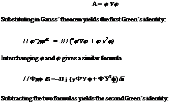
Panel methods are based on Green’s identities. The derivation starts with Gauss’ theorem (see Ref. [7])

General Wings in Subsonic and Supersonic Flows(6.140)

where S is the surface of the obstacle and £ is the outer boundary. The volume of fluid in between is denoted by P (the minus sign results from taking the unit normal outward from the solid surface).

Let ф and ф be two continuous functions with continuous first and second deriv­atives in the volume P, and let

Подпись: A = ф Уф Substituting in Gauss’ theorem yields the first Green’s identity: / / ф~дфdS = -// / (vф'Уф + ф У2ф) Interchanging ф and ф gives a similar formula / / Фдф dS =~JJ j {уФ'У ф + Ф У2ф) dїї Subtracting the two formulas yields the second Green’s identity: Подпись: (6.141)
General Wings in Subsonic and Supersonic Flows

J Js+sfydto “ "^l^dS = ///(Ф V 2ф – ф У2Ф) dїї (6.144)

If both ф and ф satisfy the Laplace equation, the right-hand-side vanishes and we have only surface integrals, in terms of ф and ф and their derivatives normal to the surface.

Now, let ф be the potential of a flow over a wing and ф be the potential due to a sink at a point P with coordinates (xP, yP, zP). The potential ф is given by

11

ф = (6.145)

4n rp

where rp = V(x – xp)2 + (y – yp)2 + (z – zp)2.

General Wings in Subsonic and Supersonic Flows General Wings in Subsonic and Supersonic Flows Подпись: ф da (6.146) a dn

To apply Green’s identity, the point p must be excluded by centering a sphere a around it with exterior normal, thus

Over the surface a,

Подпись: lim a^0 Подпись: дф d nПодпись: da = —ppGeneral Wings in Subsonic and Supersonic Flows(6.147)

and

lim da = 0 (6.148)

a^0 a dn

Подпись: фр Подпись: (6.149)
General Wings in Subsonic and Supersonic Flows General Wings in Subsonic and Supersonic Flows General Wings in Subsonic and Supersonic Flows

hence,

In the above formula, the sink term (4^) and the doublet Щ (4^) represent the Green’s functions of the integral equation if the point P is chosen to lie on the surface S, while the integral on S in the far field yields the potential of the uniform flow.

The potential panel methods are based on this integral equation, where = 0 on solid surfaces. After triangulation of the surface, the values of ф at the vertices are calculated from the algebraic equations approximating the integrals, assuming ф is linear over the triangles. other equivalent methods are available in literature.

The above formulation can be extended to subsonic flows via the Prandtl/Glauert transformation.

For lifting problems, special treatment of the vortex sheet is required, where the potential itself is discontinuous. In general, the vortex sheet is floating with the flow and the pressure is continuous across such a sheet. Away from the trailing edge, the sheet will roll up and the vortex core may be modeled in these calculations (the wake can be considered a contact discontinuity and associated jump conditions must be enforced).

Finally, For nonlinear subsonic flows, the governing equation can be rewritten as a Poisson’s equation since

V.(рЧф) = pV2 ф + Vp. V ф = 0 (6.150)

hence

Подпись:2 1

V 2ф = —V p. V ф = f
p

Iterative methods can be constructed to calculate these flows. The formulation must be extended since V2ф = 0, with an extra term involving volume integrals of the non homogeneous term of the Poisson’s equation. Panel methods become less attractive since three dimensional grids are needed and the convergence of the iterative methods become a problem as the local velocity becomes sonic.

Panel methods for transonic flows are available in literature, where the formulation is based on the unsteady flow equation and artificial viscosity is added in supersonic regions for numerical stability and to capture shock waves. The reader is referred to Refs. [12, 13], for example, for more details.

Rectangular Wings

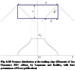
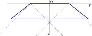
Consider supersonic flow over a rectangular wing, Fig. 6.38.

The pressure is constant along rays from the tips of the leading edge. From symme­try of pressure in the tip region, it may be shown that the average pressure coefficient is half the two-dimensional pressure coefficient. One finds the three-dimensional lift coefficient CL from (see Ref. [11]) [6] 2

Rectangular Wings

Подпись: Fig. 6.37 Superposition of elementary solutions
Подпись: Fig. 6.38 Pressure distribution at the trailing edge (Elements of Gas Dynamics 2001 edition, by Liepmann and Roshko, with kind permission of Dover publication)

Rectangular Wings Подпись: (6.139)
Подпись: PAR
Подпись: 2 Подпись: 3
Подпись: O

Fig. 6.39 Evolution of loss of lift coefficient with Mach number

The loss of lift due to tip effect is plotted in Fig. 6.39.

Wings with subsonic edges are more complicated, due to the singularity of thin airfoil theory there.

Lifting Problem

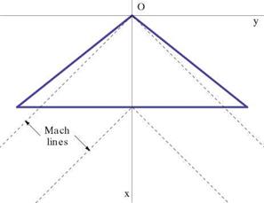
We will consider first planforms with supersonic leading and trailing edges. For such wings, there is no interaction between the flows on the upper and lower surfaces, see Fig. 6.35.

Jones and Cohen analyzed uncambered delta wings of sweep angles less than the sweep angle of the Mach lines. It is shown that ACp is constant along rays through the wing vertex, i. e. it is conical flow. The lift coefficient is independent of the sweep and it is the same as the two-dimensional result

4a

Cl = (6.137)

в

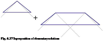
Other planforms can be also easily analyzed. For example non rectangular wings with supersonic edges, see Fig. 6.36.

Using superposition principle, the same results are readily obtained, as depicted in Fig. 6.37, see Ref. [1].

Lifting Problem

Lifting Problem

Fig. 6.35 Wing with supersonic leading and trailing edges


Lifting Problem

Fig. 6.36 Non rectangular wing with supersonic edges


Supersonic Flow Over Moderate Aspect Ratio Wings

6.10.1 Symmetric Problem

The fundamental solution is a supersonic source and the solution of the linearized small disturbance equation is given by [7]
where в = Jm0 – 1.

The source strength is determined by imposing the surface boundary condition. Hence

q(x, y) = U — (x, y) (6.134)

The domain of integration E is the part of the (x, y)-plane intercepted by the upstream Mach cone from the field point (x, y, z).

The pressure coefficient is, as before

Подпись:2 дф p U dx

It can be shown that, for an infinite wing, the surface pressure coefficient, accord­ing to the above formula, is

(x – O[5]

q(L n)_________

– в2[(y – n)2 + z2]

Подпись:

Подпись: 1 2n Подпись: d£d n
Подпись: ф(х, y, z) Подпись: (6.133)
Подпись: E

c = 2 dl = 1 де

p в dx в dx

which is consistent with the thin airfoil theory in Chap. 3.

Symmetric Problem in Subsonic Flow

Подпись: Ф(x, y, z) Подпись: 1 4n Symmetric Problem in Subsonic Flow Подпись: (6.120)

The fundamental solution is a three dimensional source/sink in subsonic flow. It is related to that in incompressible flow via the Prandtl-Glauert transformation. Hence the perturbation potential at any point in the field is obtained from the surface integral over the wing planform given by (see Ashley and Landhal [7])

where q is the density of source/sink and Lifting Problem in Subsonic Flow

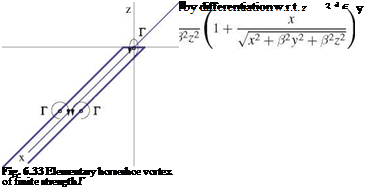
The fundamental solution for this problem is the horseshoe vortex. It consists of two infinitely long vortex filaments of same strength but opposite signs, joined together by an infinitesimal piece of the same strength, Fig. 6.33.

Symmetric Problem in Subsonic Flow Подпись: (6.131)

The potential for such arrangement can be obtained by integrating a distribution of doublets in the x-direction, with the axis of the doublet in the z-direction

Symmetric Problem in Subsonic Flow Подпись: (6.132)

Alternatively, the latter can be obtained directly from Biot-Savart law, as we did before, (see for example Batchelor [8] or Moran [9]).

6.9.1 Extended Lifting Line Theory

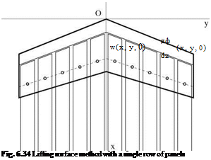
For compressible flows, swept wings are more efficient, since what counts is the velocity component normal to the leading edge. In this case, the lifting line must be modified to take into consideration the sweep angle. A simplified vortex lattice method was used successfully by Weissinger [10] with one row of panels along the loci of the quarter-chord line, as shown in Fig. 6.34. The control points, where the tangency condition is enforced, are located at the three-quarter chord line. Note that, with a single row of panels, one can only represent a flat wing, with zero camber.

Compressible Flow Over Moderate Aspect Ratio Wings

In this section, small disturbance theories for both subsonic and supersonic wings are discussed. As in two-dimensional cases, the symmetric and the lifting problems are treated separately, thanks to the linearity of the governing equations and boundary conditions, for thin wings with small relative camber and at small angles of attack. The linearized boundary condition on the plane z = 0 are

_ w(x, у, 0+) = d(x, у,0+) = U (Ш(x, у) +1 ш(x, у)- a)

w(x, y, 0-) = ^(x, y, 0-) = U Ц(x, y) – 1 ^(x, y) – a

where d(x, y) and e(x, y) represent the camber and thickness of the thin wing, respec­tively.

Notice that in the symmetric problem involving the wing thickness distribution only, the potential is symmetric with ф(x, y, – z) = ф(x, y, z), whereas for the lifting problem the potential is antisymmetric with ф(x, y, – z) = —ch(x, y, z). As in two­dimensional thin airfoil theory, across the wing surface, u is continuous and w jumps for the symmetric problem and u jumps and w is continuous for the lifting problem. The solution will be obtained as superposition of sources and their derivatives in three-dimensional flow, such that the boundary conditions are satisfied.

Incompressible Flow Over Moderate Aspect Ratio Wings: The Vortex Lattice Method

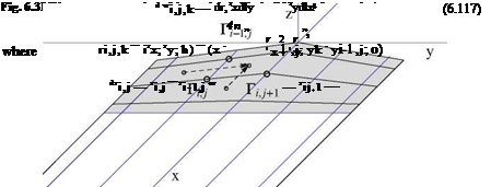
In incompressible, inviscid flow, for aspect ratio wings which are less than 7, the Prandtl lifting line theory is extended to a lifting surface theory, the vortex lattice method. For the lifting problem, consider an infinitely thin wing of equation z = f (x, y) at incidence a. The wing surface is covered with a mesh that conforms to the wing projected planform in the (x, y) plane. At the mesh node one defines the circulation Г, = r(xij, y,). Along the edges, the circulation is either zero, at leading edge and tips, or corresponds to the total bound vorticity for that cross­section inside the wing Г(у) = Г[xte(y), y], at the trailing edge. The distribution Г(y) is then carried, without alteration, along the vortex filaments to the Trefftz plane as trailed vorticity. To avoid difficulties with the singular integral, the vortices are placed between the control points as shown in Fig. 6.31.

Подпись: dVi—1 Jk Incompressible Flow Over Moderate Aspect Ratio Wings: The Vortex Lattice Method Подпись: (6.113)

The Biot-Savart law is used to calculate the components of the induced velocity at the interior control points due to the bound and trailed vorticity. For the bound vorticity, consider one of the two types of small, oriented elements of vorticity dli j = {dlx; dly; 0} = dli— 1 j between control points (i — 1, j) and (i, j) or dl, = dli;.+1 between points (i, j) and (i, j + 1). The induced velocity at point Mk = (xk, yk, 0) of the wing is given by

Vi, j,k — (xk – xh}+1; yk – yl ]+1; °)

Подпись: (6.116)

Подпись: or

Подпись:

Подпись: and

Подпись:

Incompressible Flow Over Moderate Aspect Ratio Wings: The Vortex Lattice Method

The contribution to the z-component reads

Подпись: wk Подпись: bound trailed У dwij,k + ^ dwj,k — U i,j j Подпись: (xk, yk) - a Подпись: (6.118)

The semi-infinite vortex filaments lj also contribute with the trailed vorticity to the z-component at all interior points as dwj, k. The tangency condition is enforced at the interior control points k

The Kutta-Joukowski condition is satisfied at the trailing edge by applying a parabolic extrapolation of the circulation that satisfies — 0, as was done in 2-D. Accounting for the boundary conditions mentioned above, there are as many equations as there are unknowns Г,. The linear system can be solved by relaxation. The result is the circulation at the trailing edge, r(y), that determine the lift and

induced drag of the thin wing, using the general formula derived earlier. More details on the vortex lattice method can be found in Chap. 10 on wind turbine simulation with the vortex method.

Nonlinear Lift Curve and Viscous Correction

A viscous correction can be added to the drag evaluation given by the lifting line method, by using a nonlinear viscous polar for the profiles. The viscous polar, from experiments or from the two-dimensional solution of the Navier-Stokes equations, typically displays a maximum lift coefficient at the incidence of stall a. cimax. The numerical solution of the lifting line problem becomes highly nonlinear in the vicinity of aClmax, due to the existence of two or more incidence values for a given lift coefficient Cl < Clmax. The method proposed by JJC [6], consists in adding an artificial viscosity term to the governing equation, whose role is to select the correct solution of the nonlinear problem. Lets consider the inviscid flow problem in which the lift curve presents a maximum at some value of incidence.

The governing equation for a nonlinear lift curve C; (a) reads

Подпись:Nonlinear Lift Curve and Viscous Correctiona – a0(y) + arctan

(6.104)

Nonlinear Lift Curve and Viscous Correction

Newton’s method is used to linearize locally, at control point j, the change in circulation

Nonlinear Lift Curve and Viscous Correction Подпись: (6.106)

where the change of effective incidence is expressed using the discrete formula for the downwash

Nonlinear Lift Curve and Viscous Correction Nonlinear Lift Curve and Viscous Correction

and

Nonlinear Lift Curve and Viscous Correction Подпись: (6.109)

where ш is the relaxation factor and Arj = Гп+1 – Гп. Note that aj < 0, so that, the second term in the bracket in the l. h.s. is positive as long as the lift slope is positive, and the solution can be over-relaxed. When stall has occurred on part or the whole wing, the term in the bracket changes sign and the algorithm for the circulation will no longer converge. The equation is modified with the addition of an artificial viscosity term in the r. h.s., which also contributes to the coefficient of Ar, to counterbalance the negative coefficient. The iterative algorithm now reads

Nonlinear Lift Curve and Viscous Correction Подпись: (6.110)

where the artificial viscosity coefficient vj is given by

Under-relaxation is necessary (w < 1) when separation occurs.

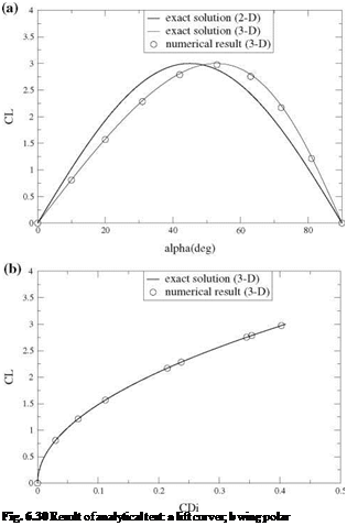
Подпись: Fig. 6.30 Result of analytical test: a lift curves; b wing polar

A simple test case, for which an exact solution of Prandtl lifting line theory can be obtained, corresponds to the elliptic loading. Consider a wing of elliptic planform and of aspect ratio AR = 7, that has no twist and no camber. The two-dimensional lift curve is given analytically by

Cl (a) = Cimax sin 2a (6.111)

The maximum lift is obtained at a = n/4. Only the first Fourier mode is present in the solution, and the downwash is constant ww/U = —A1. The governing equation reduces to

21 (y) ww

Cl(y) = = Cl = nARA1 = Cimax sin 2a + 2 arctan – , ^

Uc(y) V U )

A1 = Cimax sin (2a — 2arctanA1) (6.112)

nAR

This last equation is solved iteratively, using Newton’s method to give Ai = Ai(a). Hence the wing lift is obtained as CL(a) = nARA1(a). Here we have chosen Clmax = 3. The inviscid nonlinear lift curves and wing polar are shown in Fig. 6.30. The numerical solution matches the exact solution very well.