Category Theoretical and Applied Aerodynamics

Numerical Solution of Prandtl Integro-Differential Equation

6.7.8.1 Linear Model

Подпись: Г( y) Подпись: nUc(y) a — a.0(y) Подпись: JL ГМdn 4nU — b y — n Подпись: (6.94)

Given the wing geometry, wing span, chord, twist distributions and linear airfoil profile characteristics, C;(a) = 2n(a + 2d/c), the integro-differential equation of Prandtl allows to calculate the circulation Г(y) and subsequently the coefficients of lift CL and induced drag CDi, at a given geometric incidence a, in incompressible, inviscid flow. The equation reads

Подпись: yj Подпись: b — cos tj, 2 j ’ Подпись: tJ = (j Подпись: 1)At Подпись: J — 1 n, 0 < tj < n, J = 1,...,Jx (6.95) jx — 1

The span is discretized using a cosine distribution of points which enhances the accuracy

where Jx is the total number of control points along the span. In order to avoid the indefinite value of the integrand at n = y, the vortices of intensity 5Г(‘ф are located between the control points according to

b

Подпись: вк = (к — 1)A0 + — Подпись: 2k — 1 2(Jx — 1) ’ Подпись: 0 < вк < п, к = 1,...,Jx — 1 (6.96)

Пк = —2 cos’

The control points and vortex locations are shown in Fig. 6.26.

Подпись: У J-1 Подпись: <5Г=Г,-Г,_ 1 Подпись: *Г=І> 1-TJ Подпись: y

The geometry is discretized at the control points, i. e. the chord, Cj, the twist, tJ, and the camber, dJ. The principal value integral for wWJ is evaluated as

Fig. 6.26 Control points and vortices in the discrete representation of the lifting line

Numerical Solution of Prandtl Integro-Differential Equation

y1 rk+1 – rk 4n k—1 yj – Пк


(6.97)


wwj —


Substitution in the equation yields for the inner control points

1 у1 Гк+1 – Гк 4nU к—1 yj – Пк


Numerical Solution of Prandtl Integro-Differential Equation

rj — nUcj


j — 2,…,jx – 1 (6.98)


Numerical Solution of Prandtl Integro-Differential Equation

At the wing tips, the boundary conditions are Г1 — j — 0.

This is a linear system for the rj’s. The matrix is a full matrix with a strong term on the main diagonal which makes it amenable to point over-relaxation. Let drj — Г”+1 – j, where the upper index represents the iteration level. The domain is initialized with zero circulation by letting rj0 — 0, j — 1,… ,jx. The domain is swept in increasing values of j, j — 2,.. .jx – 1, and drj is calculated and the circulation updated immediately as Гп+1 — rj1 + АГ before moving to the next point. The contributions to АГ come from the left – and right-hand-sides upon introducing АГ in the equation

Here, a relaxation factor w has been introduced, which can be set between 1 and 2, and contributes to accelerating the convergence. Typically w — 1.5 has been used with the linear model above. The upper index (n, n + 1) term is updated with each j-equation, but some values of the circulation rk are new (n +1) and some are old (n), depending on whether к < j or к > j. Once converged, the circulation distribution provides the lift and induced drag coefficients as

2 jx – 1

SCL — U г (n – nj-1)

j—2

Numerical Solution of Prandtl Integro-Differential Equation

Numerical Solution of Prandtl Integro-Differential Equation

2y/b

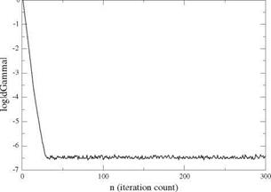
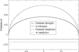
Fig. 6.27 Convergence and results for the elliptic planform wing

2 jx-1

SCot = -~2 Гwwj(nj – nj-1) (6.102)

j=2

The design of an ideal wing with elliptic planform of span b = 2.1 m and root chord c0 = 0.382 m, is carried out for a design lift coefficient CL = 0.2. The profiles are parabolic with relative camber d/c = 0.0159. The design incidence is found to be a = 0.521°. The numerical simulation is performed with jx = 101 points. The same wing is also analyzed at в = 2°. The results for the convergence, the circulation and the downwash are shown in Fig.6.27.

Note that the circulation remains elliptic and the downwash constant at off design condition. The design condition has been selected so that the wing will have an

Numerical Solution of Prandtl Integro-Differential Equation

Numerical Solution of Prandtl Integro-Differential Equation

2y/b

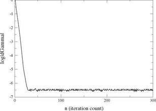
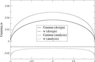
Fig. 6.28 Convergence and results for the rectangular wing

adapted leading edge. Indeed, at a = 0.521° and CL = 0.2, this wing of aspect ratio AR = 7 sees an induced incidence at = -0.521°, hence the effective incidence is aeff = 0° which is the incidence of adaptation for a parabolic profile. Each profile operates as in Fig. 6.16 (here t(y) = 0), with an incoming velocity parallel to the profile chord.

The rectangular wing with span b = 2.1m, chord c = 0.3 m of same aspect ratio as the previous one, is equipped with the same parabolic profile of relative camber d/c = 0.0159. The wing has a t(±|) = -0.0405 rad elliptical washout. At design CL = 0.2, the geometric incidence is a = 1.019°. The convergence history and the distributions of circulation and downwash are found in Fig. 6.28.

Although the analysis at off-design incidence в = 2°, shows a circulation that looks elliptic, the downwash indicates that this is not the case.

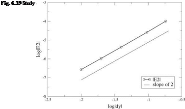
The method is second order accurate. The number of mesh points is varied from jx = 11 to jx = 201 and the numerical result compared with the analytical solution for the elliptical planform wing. The L2 error norm is used

Подпись: j=1 gj — 9 exact (yj )

Numerical Solution of Prandtl Integro-Differential Equation

1

2

(6.103)

and log |£2| is plotted versus log Ay, where the average mesh size is defined as Ay = 2/(jx – 1). The result is shown in Fig.6.29.

Extension of the Theory to Non-straight Lifting Lines

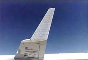
Prandtl lifting line theory has been used to analyze wing/winglet combinations and, in inverse mode, to help design wings and winglets for practical low-speed aircraft applications. The seminal work of Munk [4], a student of Prandtl in Gottingen, paved the way to understanding the contributions of these small elements placed at 90° to the main wing, which clearly do not contribute to lift, but are shown to improve the wing efficiency by decreasing the induced drag of the main wing. In Fig. 6.24, winglets are equipped with tufts to analyze the flow field during flight.

For large aspect ratio wings, the theory can be extended to lifting lines having kinks as in the case of winglets, or having a continuous curvature that turns its direction ±90°, for so-called “blended winglets”, or also being turned in the flow or against the flow direction for backward or forward sweep, as well as combinations of those. All cases have been considered by Munk, for single lifting line and multiple lifting lines. The vortex sheet takes the shape of the base surface, touching the lifting line, considered the base line. The rolling-up of the sheet edges is again neglected in the mathematical model.

JJC [5] has developed an optimization code that calculates the optimum circulation distribution along a lifting line that has a kink, for the design of winglets.

In order to find the wing/winglet combination that has the minimum induced drag for a given lift, the following objective function F(F) = CDi + ACL is defined. CDi is the induced drag coefficient. A is the Lagrange multiplier that governs the target lift. CL is the lift coefficient and is added to the objective function as a means of enforcing the lift constraint. Let a be the dimensionless winglet height normalized

Extension of the Theory to Non-straight Lifting Lines

Fig. 6.24 Research on winglet from http://www. nasa. gov/centers/dryden/about/Organizations/ Technology/Facts/TF – 2004-15- DFRC. html


with the semi-span, b/2. The lift and induced drag coefficients are

Extension of the Theory to Non-straight Lifting Lines

AR

~2


(6.89)


Cl


Extension of the Theory to Non-straight Lifting Lines

AR f1+a

Cot = — Г (a)qn(a)da (6.90)

2 -1-a

where a is the curvilinear abscissa along the dihedral shape, and qn is the induced velocity component perpendicular to the dihedral line in thex = 0 plane, with qn = w the usual downwash along the main part of the wing, qn = v on the left winglet and qn = —v on the right winglet. The “normalwash”, qn, depends linearly on Г as

l_ Г1+a Г, (y(s) — y(a)) % + (z(s) — z(a)) % da

4n — 1—a (y(s) — y(a))2 + (z(s) — z(a))2


qn(s)


(6.91)


All quantities have been made dimensionless with the half span, b/2, and the incoming flow velocity aligned with the x-axis, U. The area of reference is the projected wing area, S. The minimization equation is a function of Г only, in this inviscid model, and is obtained by taking the Frechet derivative of the objective function, which reads

dF d CDi dCL

(6Г) = — (6Г) + X L (6Г) = 0, V 6Г

дГ( ) дГ ( ) + дГ ( ) ’

Extension of the Theory to Non-straight Lifting Lines

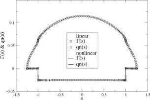
Fig. 6.25 Circulation and normalwash distributions for the optimum wing with 25 % winglet (analysis)

The boundary conditions are Г(-1 – a) = Г(1 + a) = 0. The Frechet derivative can be defined as

d

lim {F (Г + 96Г)} (6.93)

9^0 dd

and is termed “the derivative of F w. r.t. Г in the direction 5Г”. The result is linear in 5Г.

Since CDi is homogeneous of degree two in Г and CL of degree one, the min­imization equation is linear non-homogeneous in Г when X = 0. The solution is obtained in two steps: first the Lagrange multiplier is set to an arbitrary non-zero value, say X = 1 and the corresponding circulation and lift CL are calculated. Then, the final answer is obtained by multiplying the circulation by к = CLtarget/CL.

As a test case, a wing with 25% vertical winglets is designed and then analyzed for a lift coefficient Cuarget = 1. The results for the circulation and “normalwash” are shown as solid symbols in Fig. 6.25, for a selected geometry (zero twist, constant relative camber) corresponding to the optimum circulation and linear or nonlinear lift curves. The computation uses a fine mesh of jx = 101 points, including the winglets, with a cosine distributions of points on each element. This is required because the normal induced velocity is singular at the wing/winglet junction for the optimization equation, and small mesh steps are needed there. It can be noted that the winglets do not contribute to the induced drag as the normal induced velocity qn is zero at the winglets, which is in agreement with the theory [4]. The winglets are loaded, although much less than the wing. Their role is to redistribute the loads on the wing and decrease the induced drag by lowering the root circulation and by increasing it near the wing/winglet junction. The downwash on the wing is again constant, but of smaller absolute value compared to the elliptic loading. More details on the design of the geometry can be found in Chap. 11, Sect. 11.7.

Example of Wing Loading with Upwash

Подпись: WT (t) Example of Wing Loading with Upwash Подпись: (6.85)

When considering Fig. 6.16, one is tempted to design a wing loading with “upwash” on a part of the wing, to locally create a “thrust” or “negative drag” to mitigate the induced drag on the rest of the wing. This can be achieved by combining some odd modes of the Fourier series for the circulation. As seen previously, the downwash in the Trefftz plane is given by

For mode 1 this is a constant downwash

Подпись: (6.86)W1T = — 2UA1

Example of Wing Loading with Upwash Подпись: (6.87)
Example of Wing Loading with Upwash

For mode 3 this is a parabolic downwash

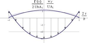
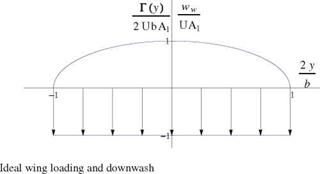
A combination for which A3 = —A1 /6, with all the other modes suppressed, gives the results for the circulation and the downwash of Fig. 6.23.

The thin lines are for the elliptic loading and constant downwash. The thicker lines show the combined 1 and 3 modes. The last 10 % of the wing span sees an upwash and a thrust. Nevertheless, since it was proved that the elliptic loading is the optimum solution, the induced drag of the wing is increased according to the formula

Example of Wing Loading with Upwash

Example of Wing Loading with Upwash

Fig. 6.23 Wing with upwash near the tips


Example of Wing Loading with Upwash

CDi


(6.88)


Example of Wing Loading with Upwash

a drag increase of 8 %.

Pitching Moment

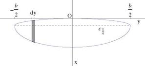
Consider a thin wing with unswept quarter-chord as shown in Fig. 6.22.

A small section of the wing of thickness dy contributes to the lift force according to

1 2

dL = pU Г( y )dy = 2 pU 2Cf (y)c( y )dy (6.78)

and to the pitching moment about the y-axis as

dM, o = dM, a.c. Xa. c.dL (6.79)

The term dM, a.c. is the contribution to the pitching moment at the aerodynamic center of the profile and is given by

dM, a.c. = 2 pU2 c2( y)Cm, a.c.( y)dy (6.80)

In thin airfoil theory the aerodynamic center pitching moment coefficient depends on the relative camber, as Cm, a.c. = —nd(y)/c(y). The negative sign is for a nose down moment. Combining the two results and integrating along the span yields

Pitching Moment

a. c.( y)c2( y )dy — 2 pU 2 Xa. c


Cl(y)c(y)dy (6.81)


Cm


Pitching Moment

Assuming for simplicity that the profile relative camber is constant along the span, the moment coefficient at the aerodynamic center is constant and the integration can be performed as

Подпись:12

M, o — 2pU ScCm, a.c

Here, we have introduced the average aerodynamic chord c. It is used, with the wing area S, to define the pitching moment coefficient

Подпись:xax.

CM, o = CM, a.c. = CL

c

Подпись: CM,a.c. Подпись: 1 Sc Pitching Moment Подпись: (6.84)

The wing aerodynamic center pitching moment coefficient is defined more gen­erally as

Local and Global Lift Coefficients

As seen earlier, the local lift coefficient is related to the local circulation by

Substitution of the circulation in the formula for the global lift coefficient and choosing Aref = S yields

Local and Global Lift Coefficients Local and Global Lift Coefficients Local and Global Lift Coefficients

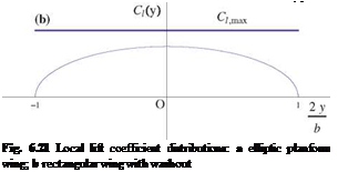
The global lift coefficient is the area weighted average of the local lift coefficient. In particular, if Ci (y) = const. the global lift is equal to the local lift coefficient, Cl = Ci. This is the case for the ideal wing with elliptic planform. For the ideal wing with rectangular planform, the local lift coefficient is elliptic and given by

These distributions are shown in Fig. 6.21 for the two wings having the same Cl.

Local and Global Lift Coefficients Подпись: 1 ll b

Here we have assumed that the wings are equipped with the same profile. If, at the operating Reynolds number, the profile lift curve has a maximum lift coefficient Ci, max, one can speculate that the elliptical wing will see stall occurring at once from tip to tip when the effective angle of incidence will reach the incidence of maximum Cl. On the other hand, the rectangular wing will stall first in the root section, where the maximum local lift coefficient is found. From the point of view of airplane design, it is desirable to have the wing stall in the root section first, because tip stall will send the plane into a spiral motion from which it is more difficult to escape. The delta wing of Fig. 6.3b is at higher risk of tip stall.

Local and Global Lift Coefficients

Local and Global Lift Coefficients

Fig. 6.22 Elementary contribution to pitching moment


. Design of an Ideal Wing

Подпись: Г( y) Подпись: (6.62)
. Design of an Ideal Wing

The ideal wing is a wing that has an elliptic circulation or loading.

where Г0 is the root circulation to be selected. The question at hand is the following: How to design the wing so that the elliptic circulation is obtained at a given CL? As we shall see, in inviscid flow, there is an infinite number of wings that will produce
the target circulation. They differ by chord, camber and twist. Consider the Prandtl integro-differential equation, specialized to the case of ideal wing loading

Г(y) = nUc(y) {a – a0(y) + at} (6.63)

where a is the geometric incidence and at the constant induced incidence corre­sponding to elliptic loading Г(у) = Г0л/1 – (2y/b)2. One recalls that a0(y) = – (t(y) + 2d(y)/c(y)).

Подпись: c0 Подпись: 2Г0 4b -, AR = UCL nc0 Подпись: a — a0 + Подпись: CL 2п Подпись: (6.64)

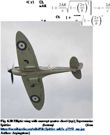
The simplest design is one in which the twist is zero, t(y) = 0, and the relative camber is constant, hence a0(y) = const. In this case, the bracket term is constant and the design is obtained with an elliptic chord distribution c(y) = с0л/1 – (2y/b)2. The root chord, aspect ratio and geometric incidence, can be found to be

Подпись: Г [ y(t)] Подпись: nUc0 sin t . Design of an Ideal Wing Подпись: TO 2U^2^An sin nt (6.65) n=1

Here we have made use of the area of an ellipse, S = | bc0. However, such a wing will develop an elliptic distribution of circulation at all incidences since it is easy to see that at a different incidence в

where we have used the Fourier expansion of the circulation and the identity sin t = л/1 – (2y/b)2. The two Fourier series will be equal if only if

2п(в – a0)

A1 = 2-, A2 = A3 = •••= An = 0, n > 2 (6.66)

пШ (1 + Ar)

proving that the circulation is elliptic at the new lift coefficient

Cl (в) = nARA1 = 2 (в – a0) (6.67)

l1 + AR)

Such a planform corresponds to the WWII Spitfire airplane unswept wing shown in Fig. 6.20.

Another design, which is attractive for ease of construction of small remote control airplanes, consists of a constant chord wing. The integro-differential equation of Prandtl now reads

Г(y) = nUc {a – a0(y) + at} (6.68)

where c is the wing chord and at the constant induced incidence corresponding to elliptic loading. Solving for a0(y) and letting AR = b/c yields

. Design of an Ideal Wing Подпись: (6.70)
Подпись: (6.69)

. Design of an Ideal WingFor simplicity, assume that the relative camber is constant and that the twist is a function of y. One finds
But, since without restriction, one can choose t(0) = 0, this determines the angle of incidence at design Cl

Подпись:. Design of an Ideal Wing

. Design of an Ideal Wing Подпись: 2AR 1 + п Подпись: 2d c
Подпись: (6.71)

(6.72)

The rectangular wing requires an elliptic washout with a tip twist of -2Cl/п2. If this twisted rectangular wing operates at an incidence в, different from the design incidence a, the circulation is no longer elliptic and is given by

2Cl ^ sin ив ^

Г[y(ff)] = nUc в — a + г sin в — nAn = 2Ub An sin ив

п2 sin в

n=1 n=1

(6.73)

A1 is equal to the new value Cl (в)/(nAR), unknown at this stage, and the other coefficients need to be calculated using the orthogonality property. For example, multiplying both hand-sides by sin в and integrating on [0, п] gives a first relation between the Fourier coefficients (note that we only consider the odd modes for reason of symmetry)

TO

y^A2p+1 = в — a (6.74)

p=1

It seems likely that the solution will involve the infinite series of coefficients. A numerical solution is the best way to obtain the value of Cl(в).

Clearly, other designs are possible with different distributions of twist, camber and chord.

Induced Drag for Non-ideal Wings

For non-ideal wings, let 6 be the relative drag increase compared to the ideal wing, i. e.

Подпись: 6 =Induced Drag for Non-ideal Wings(6.52)

With this notation, the induced drag reads

C2

CDl = nARA(1 + 6) = (Cdi)elliptic (1 + 6) = nR(1 + 6) (6.53)

The wing efficiency parameter is defined as e = 1/(1 + 6) so that, in terms of e the induced drag becomes

Подпись:Подпись: (6.54)

Подпись: Fig. 6.18
Induced Drag for Non-ideal Wings

C2

CL

neAR

6.7.1 Wing Lift Curve and Drag Polar

Подпись: ArefCL Подпись: 2 U Induced Drag for Non-ideal Wings Induced Drag for Non-ideal Wings Induced Drag for Non-ideal Wings Подпись: c(y)dy Подпись: (6.55)

The relation CL (a) is now derived for a non-ideal wing. Let a be the geometric incidence for short. Starting from the formula for the lift coefficient in which the circulation has been replaced by the right-hand-side of Prandtl integro-differential equation, one obtains

where

Подпись: 1 f 2 a0 = S a°( y)c( y)dy, Induced Drag for Non-ideal Wings Подпись: (6.57)

Now, define averaging quantities with the wing area S such as

Подпись: CL Подпись: 2n {a — a0 — A1 (1 + T)} = 2n Induced Drag for Non-ideal Wings Подпись: (6.58)

The value of t ranges between 0.05 and 0.25 according to Glauert [3], for non­ideal wings. Often t will be neglected. Upon elimination of A1 this leads to

Finally, solving for Cl

Подпись:Cl(a) = 2(1+t) (a — a0)

1 + AR~

This result is remarkable in that it gives the lift slope for a finite wing in terms of the aspect ratio

Подпись:(6.60)

Induced Drag for Non-ideal Wings Подпись: CD(O)
Подпись: (6.61)

In the limit of very large aspect ratio, the 2-D result of thin airfoil theory is recovered. Furthermore, a0 can be interpreted as the incidence of zero lift for the finite wing. Note that, as was the case for thin airfoil theory, this linear model does not provide a maximum lift coefficient as the full potential equation would. The lift curve is a straight line, but good agreement with real flow lift coefficient will be obtained for small angles of incidence. If a viscous drag coefficient is added to the induced drag, using, say, a flat plate formula based on the wing Reynolds number and the wetted area, an approximation to the wing polar can be constructed as

Assuming a constant Reynolds number, the polars are parabolas. The wing lift curves and polars are shown for different aspect ratios in Fig. 6.19.

Prandtl Lifting Line Theory (Incompressible Flow)

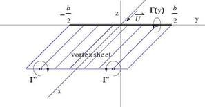
In incompressible flow, for large aspect ratio wings, i. e. AR > 7, Prandtl [2] imagined the following model for the flow, shown in Fig. 6.15.

The flow is described as a lifting line and a semi-infinite vortex sheet, made of vortex filaments which run from x = —ж to x = 0, turn abruptly along the y-axis and turn again to leave toward the Trefftz plane. The wing of Fig. 6.7b has been collapsed along the y-axis, between – b/2 and b/2. The circulation Г(y) fully describes the vorticity content of the flow, i. e. the bound vorticity inside the wing, as well as the trailed vorticity, Г'(y), of the vortex sheet. The circulation Г(y) is found by matching the local flow incidence with the profile characteristics at a given wing cross-section y, as if in isolation or part of an infinite wing. This is the so-called strip theory, which has proved useful for slender lifting elements such as large aspect ratio wings, helicopter and wind turbine blades. Mathematically, this corresponds to neglecting the derivatives along the span in comparison to the other derivatives, in other words, д/дy ^ d/dx, d/dz.

On a more historical note, Prandtl initially thought of representing the flow vor – ticity with a single horseshoe vortex of finite intensity corresponding approximately to the maximum circulation in the wing. However, he soon realized that the induced drag of a finite vortex is infinite because the azimuthal velocity component varies as 1 /r, where r is the distance from the vortex center, so that v2 + w2 a 1 /r2, which in the Trefftz plane integrates as ln r, a diverging integral over the vortex, yielding an infinite drag.

Lets assume that the profiles that equip the wing are characterized by their 2-D lift coefficients Ci(a), known from thin airfoil theory, say C;(a) = 2n(a — a0), where a0(y) = —2d(y)/c(y) represents the incidence of zero lift and d(y)/c(y) is the relative camber. The setting angle or twist of the wing, t(y), is an additional geometric parameter. Note, that, without restriction, one can set t(0) = 0 for a symmetric wing. Negative values of t(y) or nose down toward the wing tips is called washout, whereas positive values or nose up is called washin. Figure 6.16 depicts the local working condition of the profile in the y = const. plane.

Prandtl Lifting Line Theory (Incompressible Flow)

Fig. 6.15 Prandtl model for large aspect ratio wing

q

Fig. 6.16 Matching of local incidence and local lift coefficient

The profile setting angle with respect to the x-axis is given by ageo +t(y), where ageo corresponds to the geometric incidence given to the wing. The effective inci­dence of the profile is aef = ageo +1 + ai, where we have accounted for the induced incidence. The local lift coefficient is therefore

Ci(y) = 2n ^aeffiy) + 2 y^ = 2n ^ageo + t(y) + 2cy) + ai(y)^

Подпись: (6.39)

Подпись: U Подпись: x
Prandtl Lifting Line Theory (Incompressible Flow)
Подпись: geo

= 2n (ageo – a0(y) + ai(y))

For the wing with twist, a0 = -(t + 2d/c). The relation between the circulation and the local lift coefficient, as seen before, is

2Г( y)

Ci (y) = (6.40)

Uc(y)

Подпись: Г( y) Подпись: nUc( y) ageo - a0(y) Подпись: (6.41)

Here, we have replaced q with U since ai = ww /U is small. Substitution of the local lift coefficient in terms of the circulation and of the formula for the downwash at the lifting line, yields the integro-differential equation of Prandtl

Two types of problems are commonly considered: the analysis and the design problems. In the analysis problem, the wing geometry is given, that is c(y) and a0(y) are known. The objective is to find the circulation Г, the lift and the induced drag for different values of the geometric incidence ageo. In general, this problem does not have an analytical solution and can only be solved numerically. This is particularly true if the planform has kinks as in the case of the trapezoidal wing. The numerical approach will be described later.

As a designer, one can study the properties of a wing having a given loading, Г(y), and relate the loading with the induced drag in order to obtain the minimum drag for a given lift. It will remain to find how to build such a wing. In this inverse approach, as was done in thin airfoil theory, the circulation is represented as a Fourier series of sines, after a change of variables from y to t

An sin nt

Подпись:

Prandtl Lifting Line Theory (Incompressible Flow)

n=1

y(t) = —b cos t

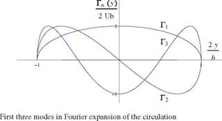
Note that, unlike in thin airfoil theory, the series contains only regular terms that satisfy the boundary conditions at the wing tips Г(0) = Г(п) = 0. Note also that the development is for Г not Г’. The first three modes Гп(y) are shown in Fig. 6.17.

It can be seen that the even modes are antisymmetrical and will induce a rolling motion to the wing. In symmetrical flight, only the odd modes are present in the solution.

Substitution of the Fourier series in the formula for the lift coefficient along with the change of variable yields

^ п b 2 Г 2 2

Are/Cb = 4b An sin nt sin tdt = 2b2A1 sin2 tdt = nb2A1 (6.43)

n=1 J° 2 J°

where we have exchanged integration and summation, and used the orthogonality of the Fourier modes. If we choose as reference area the wing area, i. e. Are/ = S, then the result is

Cl = nARA1 (6.44)

The lift depends on the first mode only.

Подпись: WT [ y(t)] Prandtl Lifting Line Theory (Incompressible Flow) Prandtl Lifting Line Theory (Incompressible Flow)

The induced drag is now considered. First, one evaluates the downwash in the Trefftz plane by substituting the Fourier expansion in the formula for wT to get with П = cos в

where again, integration and summation are switched, and the result, taken as prin­cipal value integral, can be found in books of integrals.

Prandtl Lifting Line Theory (Incompressible Flow) Подпись: (6.46)

The expression for wT can now be inserted in the formula for the induced drag as

where we have use orthogonality of the Fourier modes, term by term, from the product of the two series. Let Aref = S, then the result reads

O

CDi = nAR^ nA2n (6.47)

n= 1

Prandtl Lifting Line Theory (Incompressible Flow)

This result proves that the induced drag is zero only if all the coefficients are zero, that is if Г(y) = 0. This is the case with a flat plate wing at zero incidence. For a given, non-zero lift, A1 = 0, the minimum drag is obtained when A2 = A3 = ••• = An = ••• = 0, n > 2. Such an ideal wing has a circulation distribution given by

Drag

The drag is given by Viviand as

Подпись:u v w

d£, — 2 Hy +—- nz d^R

JsRUU y U V R

— ArefCDi + ArefCDw (6.20)

where n — {0; ny; nz} is the normal unit vector to SR. The two terms are interpreted, the former as the induced drag due to the vortex sheet, the latter as the wave drag due to shock waves in supersonic flow. The induced drag refers to the drag induced by lift or vortex drag. If the circulation is zero, there will be no vortex sheet and the first term will vanish.

Drag

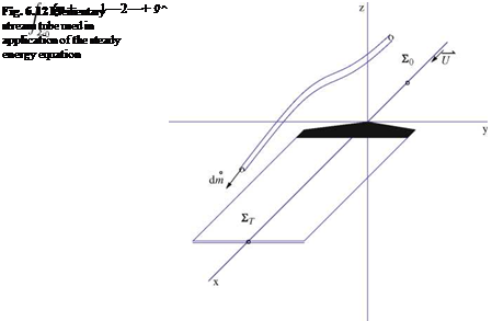
It is also possible to derive the formula for induced drag from the steady energy equation for small disturbance flow. Consider the small stream tube entering through the plane S0 and exiting at the Trefftz plane, Fig. 6.12. The steady energy equation applied to all such small stream tubes yields

The internal energy term u = Cv T, and the pressure/density term cancel out as the flow returns to its free stream temperature, pressure and density. The gravity term is neglected. Ws represents the shaft work done to the fluid. Upon simplification, this reads

One can see that the kinetic energy leaving the Trefftz plane is larger than the kinetic energy entering through the S0 plane. Work has been done to the fluid. The work is due to the thrust that is needed to balance the induced drag to maintain the steady motion of the wing in the frame where the fluid is at rest in front of the wing. The induced drag is present, even in inviscid flow. It can be written

1 3

Ws = – T. U = D. U = 2 P^U 3ArefCot (6.23)

Подпись: ArefCDi — ST Drag Подпись: (6.24)

Upon substitution of the definition of the induced drag coefficient, one finds

Подпись: v2

The surface integral can be transformed into a contour integral along the trace of the vortex sheet. Consider the identities

Drag Подпись: (6.26)

The induced drag now reads

The last integral vanishes since, in the Trefftz plane, the flow is two-dimensional with u = 0 hence д2ф/дх2 = 0 and the governing equation reduces to the Laplace equation in the (y, z)-plane. The divergence theorem is applied to the first integral where the vortex sheet is excluded in order to have a simply connected domain with a

Fig. 6.13

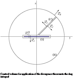
Подпись: Control volume for application of the divergence theorem to the drag integral

contour made of a large circle (R) of radius R in the far field, a contour (S) surrounding the sheet and a cut (C) to connect them, as shown in Fig. 6.13.

Подпись: ArefCDi Подпись: f ф дф_дф_ U2 JR+S+C ф d y ’ dz Подпись: .ndl Подпись: (6.27)

The integral now reads

Подпись: ArefCDi Подпись: f ф дф/дф_ U2 S ф d y ’ dz Drag
Drag

The contribution on (R) goes to zero as R since ф and Vф vanish far away from the vortex sheet. The integral on (C) is zero from continuity of the integrand and change of sign of the normal vectors. There remains

Подпись: ArefCDi Подпись: 1 U2 Drag Подпись: (6.29)

where we have accounted for ny = 0, n+ = — 1and nz = 1, and replaced the contour (S) by the segment [— |, |]. We have seen that the w-component is continuous across the vortex sheet, and the jump of the potential is the circulation, i. e. Г(y) = ф+ — ф— =< ф >. The result follows

where wT stands for the vertical component of the induced velocity in the Trefftz plane. It will be seen that the vortex sheet trailing a thin wing with positive lift induces a negative component w above and below the sheet, called the downwash. The downwash is responsible for the induced drag. According to the 2-D result of thin airfoil theory in incompressible flow, the contribution to the downwash at a point y of the vortex sheet due to an infinite vortex line of intensity dГ = Г’dn located at n is given by

Подпись:1 Г’

2n y – n

Подпись: WT (y) Подпись: 1 Ґ ГМ dn 2n — * y — n Подпись: (6.31)

and the resulting wT reads

In incompressible flow, one interpretation of the induced drag is obtained by revisiting the Kutta-Joukowski lift theorem applied to a section of the wing, but accounting now for the downwash. Lets assume that there is a downwash ww (y) induced by the vortex sheet in the neighborhood of the wing. The bound vortex sees an incoming flow that has been deflected down, as shown in Fig. 6.14.

The angle between the undisturbed velocity vector U and the velocity vector q seen by the profile is called induced incidence. The induced incidence a. t (y) = tan-1 (ww(y)/U) ~ ww(y)/U is negative, in general, for positive lift. The lift contribution is unchanged by the induced incidence since cos a. i ~ 1. The induced element of drag is given by

dDt = – dF sin at ~ – p^Ur(y)atdy = – p^r(y)ww(y)dy (6.32)

Подпись: ArefCDi Drag Подпись: (6.33)

The induced drag coefficient therefore becomes

Подпись: Fig. 6.14 Interpretation of induced drag in incompressible flow Подпись: w

This result is consistent with that derived earlier, because at the wing, application of the Biot-Savart formula in incompressible flow shows that the induced velocity is

Подпись: ww (y) Drag Подпись: 1 2 WT (y) Подпись: (6.34)

half that in the Trefftz plane, since the contribution of a semi-infinite line vortex is half that of an infinite one, i. e.

The formula for the induced drag can be manipulated upon substituting the down – wash as

b b,

1 Г2 [2 r'(n)

Подпись: b b '2 ° 2

Drag Подпись: Г '(n) Drag Подпись: (6.35)

f = 2nW_b/bГ( y^n

Using integration by parts for the integral in the bracket, yields

Подпись: ArefCDl - 2nU2^ Г'(n) [Г(y) ln |y – n|]-b – f b_ Г'(y) ln Iy – nldy I dn

Drag Drag

The integrated term in the bracket is zero since Г (±— 0, thus we are left with a symmetrical expression for the induced drag that reads

Interestingly, in slender body theory, a similar formula can be derived for the wave drag. Indeed, away from the body, the disturbance potential behaves as if the body is a body of revolution and the leading term in the expansion of the potential solution corresponds to a distribution of sources along the axis that depend on S'(x), where S(x) represents the cross-section area of the body of length l. If furthermore the body satisfies S'(0) — S'(l) — 0, that is if the body is finite or connects to a cylindrical part, the wave drag reads

ArefCDw –1 S"(x)S"(0 ln |x – eidxde (6.38)

2n 0 0

This analogy can be used to find the body of revolution with minimum wave drag in supersonic flow from the finite wing with minimum induced drag in incompressible flow.

Lift

Подпись: ArefCL Подпись: 2 U Lift Подпись: Ф ) dy Подпись: 2 Г2 и ьГ(y)d 2 Подпись: (6.17)

Viviand showed, after lengthy calculations, that the lift coefficient is given by

Here we substituted ф for єф1. This result is consistent with the Kutta-Joukowski lift theorem. Indeed, if one considers a section dy of the wing with bound vorticity Г(y), the element of lift is

Подпись: (6.18)dL — p^U Г (y)dy

Подпись: L — рж U Lift Подпись: (6.19)

and is perpendicular to the incoming flow. The total lift will be

and the lift coefficient based on the reference area Aref given by the above formula.