Category Theoretical and Applied Aerodynamics

Forces

The momentum theorem applied to a large control volume surrounding the wing and bounded by a surface £, yields the resulting force

F =-J (pV(V. n) + pn) d£ (6.13)

When the flow on the wing does not present singularities, such as a leading edge singularity, thanks to an adapted leading edge, the surface £ can be shrunk to the surface of the wing and the force reduces to

F =- pndA (6.14)

wing

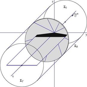
However, the flow is in general singular along the leading edge of the wing, even in supersonic flow if the leading edge sweep is large enough, and the integration of pressure will miss the contribution due to that singularity, the suction force. Hence it is best to integrate on a surface that stands away from the wing. Typically one uses a cylinder of large radius R, denoted £R, and two planes perpendicular to the x-axis to close the control volume, one far upstream where the flow is undisturbed, £0, and one far downstream treated as the Trefftz plane, £T, Fig. 6.11. The control volume surface is £ = £r U £0 U £T. On £0, the flow is uniform and V = {U, 0, 0}. Perturbations may be present on £R due to shock waves crossing the boundary in supersonic flow regime and u, v, w have jumps along the shock trace. In £T, far downstream, the flow will be perturbed in the vicinity of the vortex sheet. The pressure has returned to pro, i. e. u = 0, but v, w are different from zero, with v being discontinuous at the sheet and v, w tending to zero far from the x-axis.

The expression for F can be simplified by introducing a small perturbation assump­tion and expanding the dependent variables p, V and p with respect to a small para­meter є, where є can represent relative thickness, camber or incidence, as

p = Pro + єр1 (x, y, z) + є2р2(х, y, z) +–

V = U i + єV1 + e2V2 + ■■■ =

{U + ємл(х, y, z) + є2иа(х, y, z) +—— ;

єvl(x, y, z) + є2г02(х, y, z) +— ; .

єwl(x, y, z) + €2w2(x, y, z) +— }

. p = Pro + ProU2 {ep1(x, y, z) + Є2Р2(Х, y, z) +– )

It has been established by Viviand [1] that, to first order, the following relations hold

P1 = ~МГО u1

Подпись: (6.16)Vx = Уф, V2 = V Ф2
pi = U1

Подпись: Fig. 6.11 Control volume for the evaluation of forces. The shock surface is represented in grey
Forces

which indicate that the flow remains irrotational at the first two orders, even in presence of shock waves (assumed to be weak). Rotation and entropy appear at third order. To find the forces, the expansions need to be carried to second order, but the result can be expressed in terms of the first order perturbations only.

Two-Dimensional and Three-Dimensional Vorticity epresentations

The vorticity distributions in 2-D and 3-D have similarities and differences that can help explain the flow features and make connections between the two flow situations. First we look at the vortex filaments in a 2-D flow past an infinite wing and of the simplified 3-D model for a finite thin wing. In 2-D the vortex filaments are

Two-Dimensional and Three-Dimensional Vorticity epresentations

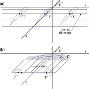
Fig. 6.7 Vortex filaments: a straight filaments in 2-D; b horseshoe filaments in 3-D

perpendicular to the plane of the profile and they carry a constant vorticity Г'(x). In 3-D, the vortex filaments have the shape of a horseshoe: they come from infinity downstream, enter the wing at the trailing edge, bend into the wing and exit at the trailing edge to trail to downstream infinity. The vorticity Г’ is constant along the filament. The part of the vortex filament inside the wing (or inside the profile) corresponds to the bound vorticity. Outside the wing, the filaments are parallel to the x-axis and the vorticity they carry is called trailed vorticity, all the way to the plane at downstream infinity called the Trefftz plane, Fig. 6.7.

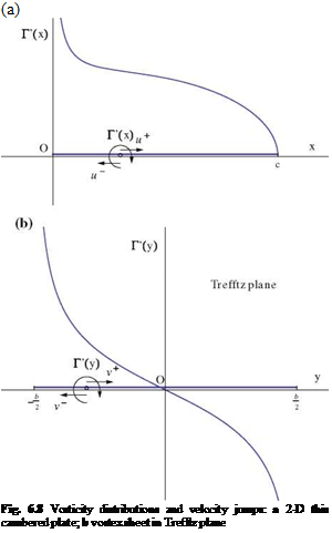
The bound vorticity inside a profile and the trailed vorticity in the vortex sheet give rise to a discontinuity in the velocity field. Consider for example a thin cambered plate in 2-D and the trace of the vortex sheet in the Trefftz plane in 3-D, Fig. 6.8.In 2-D, the vorticity along the x-axis is responsible for the jump in u across it, with u(x, 0+) = Г'(х)/2 and u(x, 0-) = —r'(x)/2. In the Trefftz plane, the situation is identical to that inside the profile in 2-D, with an infinite straight filament responsible for the jump in v across the vortex sheet, where v(<x>, y, 0+) = Г'(у)/2 and v(<x>, y, 0—) = — Г ‘(y)/2.

Note that, in general, Г'(±b/2) = ^сю, that is the flow at the edge of the vortex sheet behaves as at the leading edge of a thin plate. The velocity components v and w are infinite. Note also that the flow satisfies a Kutta-Joukowski condition at the trailing edge in 2-D and 3-D.

The circulation is the integral of the bound vorticity inside a profile according to dГ = Г’dx. At the trailing edge the value Г(с) obtained corresponds to the total vorticity inside that profile. Downstream of the trailing edge the circulation is a

Подпись: (a) Fig. 6.8 Vorticity distributions and velocity jumps: a 2-D thin cambered plate; b vortex sheet in Trefftz plane

function of y only, Г(y), and remains constant along the vortex filaments all the way to the Trefftz plane. This is a consequence of the pressure continuity across the vortex sheet. Indeed, < u >=< ^ >= < Ф > = ут = 0. In 2-D, for an infinite wing,

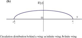
the circulation at the trailing edge, Г(y) = Г(с) is the same for all profiles, hence the velocity component v is continuous across the z = 0 plane downstream of the trailing edge. There is no trailed vorticity and no vortex sheet. Two such circulation distributions are shown in Fig. 6.9.

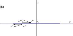
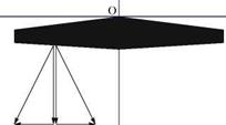
The velocity components at the trailing edge, above and below the vortex sheet of a finite wing, are depicted in Fig. 6.10. The components are continuous across the vortex sheet, except for the y-component. The same result holds at any point on the vortex sheet.

Two-Dimensional and Three-Dimensional Vorticity epresentations

(a)


F(y)


O y

Fig. 6.9


(a)


y


v


u u


v


x

Two-Dimensional and Three-Dimensional Vorticity epresentations

Fig. 6.10 Velocity vectorjump at trailing edge: a in wing plane; b cross flow plane


Two-Dimensional and Three-Dimensional Vorticity epresentationsTwo-Dimensional and Three-Dimensional Vorticity epresentations

Fundamental Feature of the Flow Past Finite Wings: The Vortex Sheet

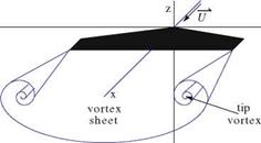
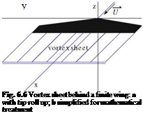
The small disturbance potential equation, governing the flow past thin wings and slender bodies, admits jump conditions which represent discontinuities in the flow. Shock waves in linearized supersonic flow are such discontinuities and correspond to jump of velocity, density and pressure across characteristic surfaces. In incom­pressible or low speed flow, shock waves do not occur. However, at all flow regimes, discontinuities of a different nature are admissible that are called vortex sheets. A vortex sheet occurs at the sharp trailing edge of a wing and trails behind it to down­stream infinity. To simplify the mathematical treatment, the vortex sheet rolling up at the edges into tip vortices is neglected. This will not affect the vorticity content of the vortex sheet, but only modify slightly its distribution in space. It has been found that this effect is of second or higher order, Fig. 6.6.

The study of the jump conditions associated with the perturbation potential equa­tion provides insight into the type of discontinuities that can be present with this flow model. First, the second order PDE is transformed into an equivalent first order system in (u, v, w) as

Подпись:Fundamental Feature of the Flow Past Finite Wings: The Vortex Sheet

Fundamental Feature of the Flow Past Finite Wings: The Vortex Sheet

y

(l _ M2 – і— dv і dw _ о

l1 M0) dx + dy + dz — 0

Подпись: (6.10)dw dv

d — d — 0

_ dw і du __ о

dx + dz — 0

Here we have used the governing equation and two components of the irrotation – ality condition. The third component is a consequence of the other two. The jump conditions for this system read

1 — Mq) < u > nx + < v > ny + < w > nz — 0

< w > ny — < v > nz — 0 (6.11)

— < w > nx + < u > nz — 0

This is a homogeneous system for the components (nx, ny, nz) of the normal vector to the jump surface. For a non-trivial solution, the determinant must vanish, i. e.

I ^1 — Mq^ < u >2 + < v >2 + < w >2J < w >— 0 (6.12)

Two cases are possible:

(i) < w >— 0. The equation reduces to (1 — M^) < u >2 + < v >2 +

< w >2— 0. A non trivial solution can only be found if 1 — Mq2 < 0, that is if the flow is supersonic. The surfaces that admit this jump condition are shock waves that coincide with characteristic surfaces of the PDE. Note that Prandtl-Meyer expansions will be represented by “expansion shocks” in this linear theory. The flow crosses the shock surface which is not a stream surface since < w > — 0. In general < v >— 0 (except in a plane of symmetry). The component u must have a jump for a non-trivial solution, i. e. < u > — 0, which indicates that the pressure is discontinuous.

(ii) < w >— 0. The jump condition is satisfied. In general < v >— 0 (except in a plane of symmetry). The fluid is tangent to the surface of discontinuity since

< w >— 0. It is called a vortex sheet. The vortex sheet is a stream surface, not a material surface, therefore it cannot withstand a pressure difference across it. This implies that < u >— 0. In consequence, the only velocity component that has a jump at a vortex sheet is the v-component.

Flow Past Thin Wings

Flow Past Thin Wings Подпись: (6.5)

The above assumptions result in the existence of a perturbation potential ф(х, y, z) that governs the disturbance flow field (u, v, w) = Уф and verifies

The full velocity is V = Ui + Уф. This linear partial differential equation is not valid near Mach one, as was seen in 2-D. Unless otherwise stated, we will consider planar wings, i. e. wings whose base surface is in the (x, y) plane. Such a wing can be described by the equation z = f ± (x, y) where the plus sign corresponds to the upper surface and the minus sign to the lower surface. f± is small and of order e/c, d/c. Setting the wing at small incidence a amounts to adding to f± the shearing term a(cr – x), as was done in 2-D.

Flow Past Thin Wings Flow Past Thin Wings

The tangency condition requires that the flow be tangent to the thin wing, V. nlwing = 0. A vector, normal to the wing, has components

The transfer of the tangency condition from the actual wing surface to the nearby base surface yields, to first-order accuracy, the following result

w±(x, y, 0±) = U ^-d———- a^ (6.8)

The Bernoulli equation for a small perturbation yields the same result for pressure as was derived in 2-D, i. e. p = рж – p^Uu, hence the pressure coefficient is

u

Cp = —2 u (6.9)

Small Disturbance Theories

Подпись: V = (U + u) i + vj + wk, s.t. Small Disturbance Theories Подпись: (6.3)

Assume inviscid, steady flow past a thin wing that disturbs only slightly the incom­ing uniform flow of velocity U, parallel to the x-axis. Let (u, v, w) be the small perturbation components. The velocity vector is given by

Since the flow is tangent to the obstacle, the condition for small disturbance is that the wing or the body makes a small angle with the x-axis. In other words, the obstacle must be close to a cylindrical surface, the base surface, generated by straight lines parallel to the x-axis and touching an arbitrary curve called the base line. In the case when the curve reduces to a point, the base surface degenerates to a line parallel to Ox called the axis of the body. In the first case, the obstacle is called a thin wing. In the second case, the obstacle is called a slender body, Fig. 6.5. Slender bodies and low aspect ratio wings are the object of Chap. 7, where slender body theory will be discussed. For the rest of this chapter, we will develop the theory for thin wings of large and moderate aspect ratios.

Note that the base line can be curved. For example, it can be an arc of a circle in the (y, z) plane, centered on the z-axis and tangent to the y-axis at the origin. If a wing geometry is drawn on such a cylindrical surface, an infinitely thin wing will be defined and the wing will have curved up tips, but as such will not disturb the incoming flow.

Small Disturbance Theories

Thickness, camber and incidence can be added to the thin wing geometry as defined above, and the same restrictions for thin airfoils apply, i. e.

Small Disturbance Theories Small Disturbance Theories

The addition of thickness, camber or incidence is expected to create a small

. Wing Geometric Parameters

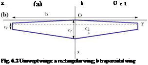
The wing planform geometry can be described with several parameters. Unswept

wings are shown in Fig. 6.2. The quarter chord c 1 is parallel to the у-axis. In the

4

case of the trapezoidal wing, the root chord, cr or c0, and the tip chord, ct, are two parameters that define the planform geometry.

. Wing Geometric Parameters Подпись: y

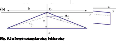
The quarter-chord sweep angle, Л c is another geometric parameter for swept wings such as the rectangular swept wing and the delta wing, Fig. 6.3.

. Wing Geometric Parameters

The delta wing is usually the preferred design for low aspect ratio supersonic aircraft wings.

Подпись: 1 S . Wing Geometric Parameters Подпись: (6.2)

One defines the mean aerodynamic chord as

The mean aerodynamic chord plays a role in the wing pitching moment.

When facing the wing and the fuselage, the angle of the wing with the horizontal plane is called the dihedral angle. The dihedral angle can be positive or negative, see Fig. 6.4. A positive dihedral angle introduces rolling stability, known as dihedral effect, but this and other unsymmetrical flow conditions such as yaw, are outside the scope of this book.

Подпись: Г. Wing Geometric Parameters(a)

Подпись: Fig. 6.4 Dihedral angles: a Г > 0; b Г < 0

(b)

Flow Past Large and Moderate Aspect Ratio Wings

In this chapter we will study 3-D steady flows past finite wings of large and moderate aspect ratios. The wing geometrical parameters have been defined in Chap. 1 with wing aspect ratio given by AR = b2/S, where b is the wing span from tip to tip and S is the projected surface area of the wing onto the x, y plane, the x-axis being aligned and in the direction of the incoming flow in the plane of symmetry of the wing, the y-axis being along the right wing and the z-axis completing the direct orthonormal coordinate system. For a rectangular wing, this reduces to AR = b/c, where c is the constant chord. The assumption of a large aspect ratio wing will contribute to a major simplification which consists in neglecting geometric influence in the y-direction compared to the other directions, in other words

д д d

« , (6.1) dy dx dz

which corresponds to the so-called strip theory. Large aspect ratio lifting elements make for the wings of commercial aircraft, glider, helicopter and wind turbine blades. Such a fundamental geometrical aspect has ramifications not only for aerodynamics, but also for structures with the beam theory. Aspect ratio varies widely:

• AR ~ 35 for high performance sailplanes

• AR = 7 — 2 for commercial airplanes

• AR = 4 — 5 for transport jets

• AR ~ 2 for supersonic jets

Note that AR > 7 will be considered high aspect ratio and AR < 4 low aspect ratio (Fig. 6.1).

© Springer Science+Business Media Dordrecht 2015

J. J. Chattot and M. M. Hafez, Theoretical and Applied Aerodynamics,

DOI 10.1007/978-94-017-9825-9_6

Falling Plate over Flat Surface

Consider the 2-D unsteady motion of a plate of width 2L falling on a flat surface a very small distance h apart where h/L ^ 1. The gap is occupied by air. The air viscosity is neglected and the flow is assumed incompressible, see Fig. 5.12.

Apply conservation of mass theorem to the control volume and show that the flow field corresponds to a stagnation point flow with a time dependent multiplication constant

u = K(t) x, w = – K(t) z

Find the relationship between K(t) and h(t).

Find the pressure in the gap by integrating the x – and z-momentum equations, and find the pressure on the lower side of the plate by enforcing the condition that the pressure should be continuous and equal to patm at the edge x = L, z = h(t).

Let M’ be the mass per unit span of the plate and assume that M’ ^ pL3/h(0), where p is the air density. Show that the plate motion is described by

h(t) _ 1

Подпись: where Подпись: C Подпись: 3 M' g 2 PL3

h(0) = cosh VCt

Fig. 5.12 Falling plate

Problems

5.4.1 Motion of a Vortex Pair Above Ground

Подпись: Fig. 5.11 Vortex pair
Problems

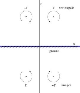
Consider to counter-rotating vortices of strength ±Г, such as trailing the wings of an aircraft. Let the z-axis be the meridian plane and the x-axis be the ground, Fig. 5.11.

The two vortices are initially located at (a, b) and (-a, b). Show, by using images of the vortices below the ground, that the trajectory of the vortices is described by

1 1 _ 1 1

x2 + z2 a2 + b2

Show that the pair of vortices does not hit the ground, but gets as close as zmin = c = ab/J a2 + b2.

Show also that, far from the ground, the vortex pair moves parallel to the z-axis with velocity w = —Г/(4пс).

Summary of Chapter 5

In this chapter, unsteady incompressible and compressible flows are discussed within the framework of thin airfoil and small disturbance approximations.

The fundamental aspect of unsteady, inviscid flow is the shedding of vorticity from the trailing edge of the thin profile. A Kutta-Joukowski condition still applies at the trailing edge to render the solution unique. The steady linear models of subsonic compressible and supersonic potential flows require a cut across which the potential has a jump equal to the circulation around the profile, Г =< ф >. In steady flow, the cut could be placed anywhere to make the domain simply-connected. However, in unsteadys flow, the cut represents the inviscid “wake” or slip line, downstream from the trailing edge, along the x-axis, where the potential function is discontinuous and the jump in potential is a function of time and space. The unsteady Bernoulli’s law (or generalized Bernoulli’s law in compressible flow) provides the condition along the slip line by specifying the continuity of pressure.

The example of the plunging plate in incompressible flow is simulated numerically and the results are compared with the exact solution. Care must be exerted to include

the suction force at the leading edge of the plate in order to obtain zero drag when the flow returns to steady-state. Noteworthy is the first instant in the simulation when the circulation in the plate is still close to zero and the vorticity distribution similar to that of an elliptic wing. The lift and drag are equal, resulting in a force perpendicular to the plate and their magnitude is inversely proportional to the time step.

Another example is the pitching NACA0012 at low speeds and low frequency.

Extension to the unsteady full potential equation is discussed. The unsteady tran­sonic small disturbance equation (unsteady TSD) is derived and the magnitude of the coefficients of the time derivatives analyzed in relation to the reduced frequency. The low-frequency TSD is highlighted as it is of great importance to the study of transonic unsteady flows. Key papers are referenced for the reader interested in more in depth exposure.