Category Theoretical and Applied Aerodynamics

The Transonic Small Disturbance Equation

The unsteady, transonic small disturbance equation (TSD) in Cartesian coordinates is given by

Подпись:(5.54)

Подпись: дфПодпись: дф

Подпись: к2M02 kM02 1 - M02 A =—И1, B =, с = ^^ є 3 є 3 є 3
Подпись: ^ +1} M дХ = K - +1} M дХ (5.55)

where

K is the transonic similarity parameter. For an airfoil of chord length c, traveling with speed U with an oscillating frequency w, the reduced frequency is defined as

к = (5.56)

U

2

The perturbation potential in the above equation is scaled by є 3, where є is the small parameter representing the profile thickness, camber or incidence, while x, y

1

and t are scaled with c, с/є 3 and 1 /w, respectively.

2

For low reduced frequencies, when к = O(є3), the equation becomes

Подпись:д2ф д2ф д2ф

2 p __ с

dt дх д x2 д у2

The Transonic Small Disturbance Equation

The pressure coefficient is

where the profile is given by у = є f (х, t).

The far field non-reflecting downstream boundary condition becomes

Подпись: (5.61)дф дф

дХ + k д =0

Notice, this condition is consistent with the treatment of the cut.

The Transonic Small Disturbance Equation Подпись: (5.62)

The shock jump condition for the unsteady TSD, low frequency approximation, is obtained from the conservation form of the equation [4]

The Transonic Small Disturbance Equation The Transonic Small Disturbance Equation

and from the irrotationality condition д2ф/дхдy = д2ф/дудх

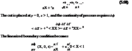
Here, we made use of < u2 >= 2u < u >, where U = (u1 + u2)/2, is the average of u across the shock. Also, nt/пх = —йхя/dt is the speed of the shock in the х-direction. With this, the shock equation becomes

2B (dt), < дф >> + (К — <Y + 1)M2 дф) < дф >2 + < д >2= 0

(5.65)

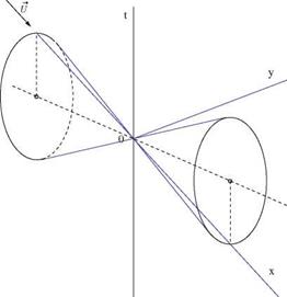
The equation is always of hyperbolic type. One family of characteristic surfaces through the origin comprises the plane t = 0 that corresponds to an infinite speed of propagation of the perturbations. The other family are planes that envelop a cone of equation

2 Bxt + Ct2 = (By)2 (5.66)

The cross section of the cone by a plane t = const is a parabola having the х-axis as axis of symmetry, Fig. 5.10. The origin is inside the parabola when M0 < 1, and outside when M0 > 1. The tangents to the parabola from the origin represent the characteristic lines of the steady flow.

Next, the sources of material of this section are summarized.

First, the linear theory for high frequency transonic flow is discussed by Landhal [5]. The more recent, nonlinear small disturbance theory is discussed by Cole and Cook [6]. The numerical treatment and numerical results can be found in the articles of Ballhaus and Lomax [7], Bailey and Ballhaus [4], Goorjian [8] and van der Vooren
Подпись: Fig. 5.10 Characteristic cone for the TSD equation
The Transonic Small Disturbance Equation

and Schippers [9]. Engquist and Majda covered the mathematics and numerics of ab­sorbing boundary conditions in [3] and [10]. Applications of non-reflecting boundary conditions to unsteady transonic flow computations were reported by Kwak in Ref. [11]. Many others contributed to NASA codes for low frequency transonic flows and flutter analysis.

Unsteady Compressible Flows

1.2.1 The Full Potential Equation

The Euler equations represent conservation of mass, momentum and energy, assum­ing inviscid and adiabatic flow. Furthermore, for isentropic and irrotational unsteady flows, the governing equations become

Подпись: = + У.(рУ Ф) = 0(5.40)dp д ( дФ д ( дФ д ( дФ dp

Unsteady Compressible Flows Подпись: (5.41)

dt + дх P дх + д y P д y + ді P ді дї

Подпись: The written boundary condition on a solid surface defined by F(x, y, z, t) = 0, can be as

dF д F

= + УФУF = 0, on F = 0 (5.42)

dt дї

where the velocity field of the surface points displacements has been replaced by the fluid velocity field, as both fields should be tangential to the surface.

To guarantee the continuity of the density and pressure across the vortex sheet, which is a slip line allowing for discontinuous tangential velocity only, the following condition must be imposed

= + V. У Г = 0 (5.43)

dt дї

where Г is the jump in the potential, Г = Ф + — Ф — and V is the mean tangential velocity. Note that the normal velocity component on the vortex sheet is continuous.

Unsteady Compressible Flows

where Vn is the normal component to the boundary and a0 is the speed fo sound of the undisturbed flow.

Unsteady Compressible Flows Unsteady Compressible Flows

Next, the governing equations are rewritten in non-conservative form and the discussion is limited to 2-D flows

The shock jump conditions of the potential formulation is given by

Подпись:дФ дФ

< P > nt + < Рдх > Пх + < Рду > Пу = 0

Unsteady Compressible Flows Подпись: (5.49)

On the shock, a normal vector is VS, where S&, у, t) is the surface of disconti­nuity. One finds

together with the condition of continuity of the potential

< Ф >= 0 (5.50)

The characteristics are obtained from the non-conservative form of the full po­tential equation as follows. Let, u = дФ/дх, v = дФ/ду and w = дФ/dt, hence

where we have made use of du/dt = dw/dx and dv/dt = dw/дy.

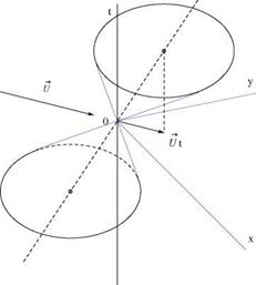
The eigenvalues of the two associated matrices are A = 0 and A = u ± a, and A = 0 and A = v ± a, respectively. The geometric interpretation of this result is that there exist two families of characteristic surfaces. Consider a point in the flow field and let it be the origin of the coordinate system. With respect to that point, one family, corresponding to A = 0, are planes that contain the t-axis. The other family are planes through the origin, that make an angle with the t-axis and envelop a cone of equation (see Fig. 5.9),

(x – ut)2 + (y – vt)2 = (at)2 (5.53)

The cross section of the cone by a plane t = const is a circle, centered at (ut, vt) and of radius r = at.

The origin is inside the circle when M0 < 1, and outside when M0 > 1. In the latter case, the tangents to the circle from the origin are the characteristic lines of the steady flow.

The zero eigenvalues can cause problems in the numerical solutions of the system of first order equations.

Unsteady Compressible Flows

Подпись: dv dw
Подпись: du

Fig. 5.9 Characteristic cone for the full potential equation

Example: Pitching NACA0012

We consider now a pitching motion. Thanks to the linearity of the problem, the combined plunging and pitching motion can be obtained by superposition of the solutions of the two motions. The following pitching motion is considered:

a(t) = a0 + Sa sin(wt) (5.39)

where a0 = 4°, Sa = 8.3°, f = 30Hz, U = 98.8 m/s and the profile chord is c = 0.1° m. This corresponds to the reduced frequency k = fc/U = 0.03. Results of the numerical simulation are compared with experimental results of Wood [2] in Fig. 5.8. The normal force coefficient is defined as Cn = Cl cos a + Cd sin a and represents the component of the force perpendicular to the profile chord. The agreement is good for the lower incidences, a < 2.5° but differences occur at high incidences due to viscous effects.

Fig. 5.8 Normal force coefficient comparison

Example: Plunging Plate

This classical test case represents a flat plate aligned with the incoming flow that is accelerated impulsively to a uniform velocity W < 0 parallel to the z-axis, | W | ^ 1. This is equivalent to setting the plate abruptly at incidence a = —W, which is the option implemented here. Although the incidence a is expected to be small in absolute value, it is possible to set it arbitrarily to the value a = 1 rad since the problem is fully linear. For any small value of incidence, the solution obtained needs to be multiplied by a. This problem has been solved numerically and the solution Г(х, t) has been compared with the numerical evaluation of the integral equation that corresponds to the solution past a thin airfoil. The integral equation reads, see JJC [1]:

Подпись: (5.34)™ , d fl+t Г(1 +1 — t)(£ + Vt(t — 1))dt na = 1 (t) + — —

dtj 1 ^£(£ — 1)(2£ — 1 + 2^t(£ — 1))

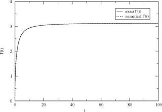
Here r(t) represents the total bound circulation Г(с, t) formulated with dimen­sionless variables or equivalently setting U = c = 1. The tangency condition is treated as indicated in Chap. 3, in the case of steady flow, but accounting now for the induced velocity contribution of the shed vortices. The results for the circulation are shown in Fig. 5.4 for At = 0.01.

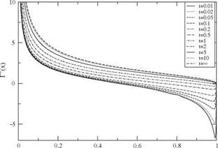
The vorticity distribution on the flat plate is displayed in Fig. 5.5. The initial low value of circulation is obtained with an almost perfectly anti symmetrical distribution of vorticity, except for the Kutta-Joukowsky condition which breaks the symmetry. The initial pressure distribution is very different from that at steady-state and the use of a steady profile polar to study unsteady flow (quasi-steady approach) would not give a realistic representation of the pressure nor of the pitching moment at the same lift in this rapidly changing flow.

Example: Plunging Plate

Fig. 5.4 Comparison of circulation r(t) obtained with thin airfoil theory and integral equation, a = 1 rad

Example: Plunging Plate

x

Fig. 5.5 Time evolution of the vorticity distribution on the plate, a = 1 rad

One notable feature of the method is the scheme and the mesh for solving the convection equation along the vortex sheet. The exact solution to the convection of vorticity is

Г(х, t) = F(x — Ut), x > c, x — Ut < c (5.35)

where F is a function of a single argument £ = x — Ut, that satisfies F(c — Ut) =

Г(с, t)

hence the exact solution is

x — c

Г(х, t) = Г c, t – , x > c, x – Ut < c (5.36)

This represents a time shift without distortion of the trailing edge circulation along the x-axis. It is possible numerically to achieve the same result with a scheme that has the “perfect shift” property. This is the case with a two-point scheme, at Courant-Friedrich-Lewy (CFL) number one

U At

CFL = = 1 (5.37)

Ax

Подпись:Подпись: в)

Example: Plunging Plate Подпись: (5.38)

and with parameter в set to в = 2. A uniform mesh is constructed with Ax = UAt to the far field point, say x = 100c. The scheme reads

This is a combined implicit/explicit scheme, which reduces to Crank-Nicolson scheme for в = 1 and is unconditionally stable for в > 2. The upper index n represents the time step and v is the inner iteration counter used to converge the circulation so that the tangency condition on the plate as well as the convection equation in the wake are satisfied to a prescribed accuracy at time tn+1.

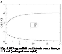
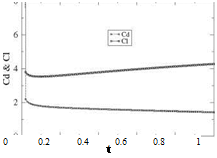
Results for the lift and drag coefficients are shown in Fig. 5.6.

Подпись: о Fig. 5.6 Drag and lift coefficients versus time, a = 1 rad (enlarged view right) Подпись: 0 0.2 0.4 0.6 0.8 1 t

The lift and drag coefficients tend to infinity near t = 0. Numerically, the common value at the first time step t = At is of order A, specifically, with At = 0.01 one

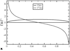
Fig. 5.7 Circulation and vorticity at time t = At

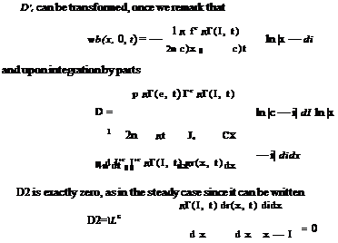
Подпись: x finds Ci = 160.5 and Cd = 158.9. Then drag decreases monotonically to zero as steady-state is approached, whereas lift decreases then increases to its final value of n. If the term D’2 had been included, the result for drag would have been Cd (t) = Cl (t) since w(x, 0, t) = —Ua =—U and (xQ — x)da + d = 0. Enlarging the scale near t = 0 provides a better look at the early evolution of those coefficients, Fig. 5.6. One can see from the numerical results that, at the first time step, the suction force is not present, but with the second time step the suction force already cancels half of the drag.
It is also possible to look at the circulation and vorticity distributions at t = At, Fig. 5.7. It is clear that at a very early time t = є > 0, the circulation must be elliptic since this gives a constant w(x, є) = a.

Unsteady Flow Past Thin Airfoils: Far Field Condition for Potential

Подпись: Ф(x, z, t) Подпись: 1 2n Unsteady Flow Past Thin Airfoils: Far Field Condition for Potential Подпись: (5.30)
Unsteady Flow Past Thin Airfoils: Far Field Condition for Potential

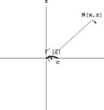
The far field value of the potential is important as boundary condition when solving the unsteady flow potential equation, using finite differences, finite volumes or finite element methods. The leading term of the perturbation potential in the far field is due to the distribution of circulation Г along the x-axis. It is the only term for thin cambered plates (zero thickness). It reads

where (x, z) are the coordinates of a point where the potential is evaluated. See Fig. 5.3.

Unsteady Flow Past Thin Airfoils: Far Field Condition for PotentialFig. 5.3 Far field evaluation of potential
Unsteady Flow Past Thin Airfoils: Far Field Condition for Potential Подпись: -( ) Подпись: 0 Подпись: 0 Unsteady Flow Past Thin Airfoils: Far Field Condition for Potential

The vorticity, dr, is in general singular at the leading edge x = 0 of the airfoil. Hence, in the numerical evaluation of the integral, it may be better to transform the expression by integrating by parts, to obtain

(5.31)

The first term vanishes at both limits, hence there remains

Подпись:1 z

ф(х, z, t) = Г(£, t) 2 2

Unsteady Flow Past Thin Airfoils: Far Field Condition for Potential Подпись: (5.33)

2n J0 (x — t)2 + z2

Unsteady Flow Past Thin Cambered Plates: Forces and Moment

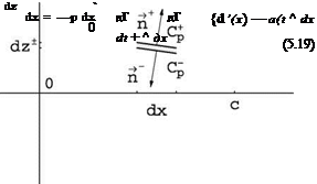
The lift and pitching moment are easily obtained from the pressure contributions in the z-direction, see Fig. 5.2.

From the figure, the elementary lift and moment contributions per unit span are dL’= (p– p+)dx, dM’, o = —(p– p+)xdx (5.13)

Unsteady Flow Past Thin Cambered Plates: Forces and Moment Unsteady Flow Past Thin Cambered Plates: Forces and Moment Unsteady Flow Past Thin Cambered Plates: Forces and Moment Подпись: (5.14) (5.15)

Hence, the global results

Подпись: дГ дГ c дГ дГ — + U dx, Mo = -p — + U дt д x 0 ді д x Подпись: xdx (5.16)Подпись: cПодпись: 0Подпись:or

L ‘ = p

Here we have made use of the linearized Bernoulli equation and of the relationship between Г and the jump in ф as

Г = ф(х, 0+, t) — ф(х, 0 , t) =< ф(х, t) >

= u(x, 0+, t) – u(x, 0 , t) =< u(x, t) > (5.17)

d x

The elementary drag contribution is seen to be

— dz ^

p ) dx
dx

Подпись: (5.18)

Unsteady Flow Past Thin Cambered Plates: Forces and Moment Unsteady Flow Past Thin Cambered Plates: Forces and Moment

Upon integrating, one obtains

It was indicated in Sect.3.5.4 that the result of pressure integration does not include the suction force that exists at the singular leading edge of a thin plate in steady flow. The same situation exists here, in unsteady flow, and can be handled in the same manner by replacing the slope of the profile, d'(x) — a(t), from the tangency condition as

pc

дГ дГ

d a

dh

D’ = —-

+ U

w(x, 0, t) — (xn — x)

U J0

д-t дx

dt

dt

dx (5.20)

Unsteady Flow Past Thin Cambered Plates: Forces and Moment

where w(x, 0, t) is made of two parts:


, 0 ^ 1 Г д г(і, t) d і, 0 „ 1 д г(і, t) d і

wb(x, 0, t) = — , ww(x, 0, t) = —

2n 0 dx x — і 2n c dx x — і

(5.21)

the first part, wb, which is to be taken in the “principal value” sense, is due to the bound vorticity and the second part, ww, is the contribution of the “wake” or shed vorticity. Substitution of these contributions in the drag evaluation yields


дГ(л, t) дr(x, t)


Unsteady Flow Past Thin Cambered Plates: Forces and Moment

д t


д x


d a dh

Wb (x, 0, t) + Ww(x, 0, t) — (xQ — x) —

dt dt


(5.22)


dx


Unsteady Flow Past Thin Cambered Plates: Forces and Moment

(5.23)

(5.24)


Unsteady Flow Past Thin Cambered Plates: Forces and Moment

d3 = —


dx


(5.25)


Unsteady Flow Past Thin Cambered Plates: Forces and Moment

(5.26)


(5.27)


(5.28)


showing the antisymmetry of the kernel.

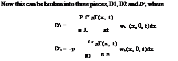
D’3 cannot be simplified much further. In summary, the drag reduces to D’ = D[ + D3, that is

Подпись: p fc д Г(х, t) Wb (x, 0, t)dx U 0 dt Подпись: dh dt Подпись:

Подпись: p Ґ дГ(х, t) U дГ(х, t) U 0 dt дх
Подпись: Ww(x, 0, t) - (XQ - x) dt

D

(5.29)

We note that, in the limit of steady flow, D1 = D’3 = 0 and D = 0.

Inviscid, Unsteady Flows Past Airfoils

In this chapter we will study 2-D unsteady incompressible flows such as flow past oscillating profiles or impulsively accelerated airfoils. The flow is assumed to be uni­form and potential in the far field. In such cases, the profile contains time dependent bound vorticity and the wake contains shed vorticity that is convected downstream and influences the profile flow conditions. An example of wake shedding vorticity is shown in Fig. 5.1. Unsteady compressible flows are also covered.

5.1 Unsteady Incompressible Flows

5.1.1 Unsteady Flow Past Thin Cambered Plates: Governing Equations

This section is the extension of thin airfoil theory to unsteady flow. Thickness is not considered here as it does not contribute to forces and moment. Consider a uniform incoming flow of velocity U parallel to the x-axis. The total velocity is V = (U + u, w), where (u, w) represent the perturbation velocity components. The governing equations are still conservation of mass and irrotationality for the perturbation velocity

Fig. 5.1 Vortex shedding from a slat trailing edge (courtesy M. Asai, Fluid Dynamics Laboratory, Tokyo Metropolitan University)


Inviscid, Unsteady Flows Past Airfoils

© Springer Science+Business Media Dordrecht 2015

J. J. Chattot and M. M. Hafez, Theoretical and Applied Aerodynamics,

DOI 10.1007/978-94-017-9825-9_5

Inviscid, Unsteady Flows Past Airfoils
Подпись: (5.1)

Note that this system is identical to that at steady-state. This is because we assume incompressible potential flow = 0). The unsteady effects will appear through the boundary conditions. Lets assume that the cambered plate can rotate by a small angle a(t) about an axis located at xQ along the x-axis and can translate parallel to the z-axis with a small amplitude h (t). The equation of the thin cambered plate at time t is given by

z±(x, t) = d(x) + (xq — x)a(t) + h(t) (5.2)

The tangency condition reads

(v’r – П = 0

profile

where V r = V — V e is the velocity of the fluid in a frame attached to the profile (relative velocity) and V e is the entrainment velocity due to the motion of the profile. The entrainment velocity for a point on the profile is given to first order by

d a dh

V‘ = (°-(xq —x)d + si) (5-4)

Hence the relative velocity is

d a dh

Vr = U + u, w — (xq — x) — (5.5)

dt dt

A unit normal vector to the profile is to first order it = (d'(x) — a(t), —1).

Подпись: w(x, 0, t) Inviscid, Unsteady Flows Past Airfoils Подпись: (5.6)

The tangency condition can be simplified by keeping the first order contributions only and, as was done in steady flow, by transferring the condition to the x-axis between 0 and c as

Such a flow can be modeled by a distribution of bound vorticity Г'(x, t) along the chord [0, c] representing the vorticity inside the profile (bound vorticity) as well as shed vorticity along the x-axis, x > c. The equation governing the shed vorticity is the linear convection equation for the circulation

Подпись:дГ д Г

Ж + U dx = 0

The solution is made unique by requiring the Kutta-Joukowski condition to hold at the trailing edge, i. e.

(c, t) = 0 (5.8)

d x

In the far field the perturbation velocity decays, except near the x-axis, when shed vorticity is present

u, w ^ 0, x2 + z2 ^ro, almost every where (5.9)

The linearization of the mathematical model will be complete with that of the Bernoulli equation. For unsteady, potential flow, Bernoulli equation reads

Подпись:дф V2 U2

p~rn + p + PT = pro + p T

Expanding the velocity term with the small disturbance assumption yields

Подпись: (5.11)дф

P + p + pUu = pro at

Inviscid, Unsteady Flows Past Airfoils Подпись: (5.12)

To first order, pressure is given by

Problems

4.9.1

A thin profile with parabolic camber d = 0-02 is set at an angle of incidence a = 5°. Find the lift coefficient Cl in compressible flow at Mach M0 = 0.7. What is the corresponding drag coefficient Cd. If the profile is attached to a vertical axis located at x = 0 (nose of profile), write the equation of equilibrium that will give the equilibrium angle of incidence aeq at M0 = 0.7. Solve for aeq, and sketch the profile at equilibrium. Is the equilibrium stable? At which axis position along the chord would the equilibrium be neutral?

4.9.2

Consider a thin parabolic plate z = 4d| (1 – x) (zero thickness) in supersonic flow M0 > 1. Give the expressions of C+(x) and Cp (x) for this profile at a = 0. Make a plot of the pressure distributions and deduct from the graph the value of the lift coefficient. Give the formula for Cl (a). Compute the drag coefficient of the thin parabolic plate for arbitrary incidence a. Make a graph of the profile polar Cl (a) vs. Cd (a). Find on the polar the value a = a f of maximum “finesse”, i. e. corresponding to maximum f = Cl(a)/Cd(a). Calculate fmax. Does the value depend on M0? If it is considered desirable to fly the airfoil at maximum finesse at M0 = 2, give the optimum value of camber d. of the parabolic profile which should be used for a given design lift coefficient Ci, design = 0-1.

4.9.3

Consider the thin cambered plate z = 71 – § (|)2 + | (|)3^ (zero thickness),

where S is a small positive number, in a supersonic flow Mo > 1. Give the expressions of C + (x) and C – (x) for this profile at a = 0. Make a plot of the pressure distributions

and deduct from the graph the value of the lift coefficient. Calculate (Cm, o) 0. If

an axis is located at f = 2 and the thin cambered plate can rotate about it and is released at zero incidence with zero initial velocity, will it rotate with nose up, nose down or stay indifferent (neglect weight)?

4.9.4

The double wedge of Fig.4.6 of half-angle в is set at incidence a in an incoming uniform supersonic flow at Mach Mo > 1. Give the expressions of C + (x) and C~ (x) for this profile at incidence a. Make a plot of the pressure distributions. Give the expression of the lift coefficient C;(a). Compute the drag and moment coefficients, Cd (a) and Cm, o(a). Make a graph of the profile polar Ci (a) vs. Cd (a). Find on the polar the value a = a f of maximum “finesse”, i. e. corresponding to maximum f = Ci(a)/Cd(a). Sketch the waves as is done in Fig.4.6, indicating shock waves and expansion fans, when the double wedge is at the incidence of maximum finesse a f.

4.9.5

Consider a flat plate at incidence a in a uniform supersonic flow at Mach Mo > 1. Sketch the shock waves and expansion “fans”, the latter being represented by expansion shocks (zero thickness). Using the jump conditions derived in this chapter, find the two components of the perturbation velocity on the upper and lower surface of the plate that satisfy the tangency condition. From these results, find the pressure coefficients and the lift coefficient for the flat plate at incidence.

4.9.6

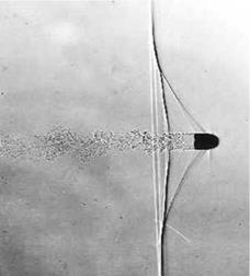
Describe and interpret what you see in Fig. 4.22 of a bullet cruising at Mach one. In particular discuss briefly: – the absence (out-of-frame?) of the bow shock, – the origin

ProblemsFig. 4.22 Problem 4.9.6: Shadowgraph of bullet at Mach = 1 (from https://en. wikipedia. org/wiki/File: Shockwave. jpg Author: Dpbsmith (Daniel P. B. Smith))
of the wave at the 50 % location from the nose of the bullet, – the lambda shock, – the base flow and how you would handle it in an approximate manner, within the small disturbance theory.

Summary of Chapter 4

In this chapter, the effects of compressibility, associated with the changing Mach number in inviscid flow, are reviewed. Thin airfoil and small disturbance assumptions are retained.

At low Mach numbers, 0 < M0 < 0.3, the flow is treated as incompressible flow.

Compressibility effects in the range 0.3 < M0 < 0.7 correspond to subsonic compressible flow and the Prandtl-Glauert rule can be applied, in the absence of shock wave, to evaluate forces and moments by solving the incompressible flow past the thin profile, then the resulting aerodynamic coefficients, Cp, Ci and Cm, o,

are magnified by the multiplying factor 1 /^J1 – M2 The drag coefficient remains Cd = 0.

Above M0 = 1.3, the flow is expected to be essentially supersonic and the linear supersonic theory and Ackeret results, are applicable and yield closed form expres­sions for the coefficients Cp, Cl and Cm, o.An inviscid wave drag is generally present with Cd > 0. The aerodynamic coefficients depend on Mach number via the multi­plication factor 1 /УМ2-!

NearMachone, intherange0.7 < M0 < 1.3, mixed-type flow is experienced with regions of subsonic and supersonic flows coexisting within the flow field. This is the transonic flow regime and the subsonic compressible and linear supersonic theories

are not applicable and yield unphysical results at M0 = 1. The nonlinear transonic small disturbance (TSD) equation bridges the gap between the two linear theories. The derivation of the TSD equation is carried out and characteristic lines and jump conditions associated with a hyperbolic equation are studied. Numerical solution of the TSD equation was needed and the breakthrough came with the Murman-Cole four-operator mixed-type scheme, which is discussed in some detail. The pressure coefficient is obtained from the numerical solution and provide the lift and pitching moment coefficients. The wave drag is shown to reduce to an integral over the shock lines impinging on the profile and hence vanishes in their absence. A rare exact solution of the TSD equation, which represents the near-sonic throat flow in a nozzle, is used to construct numerically subsonic-to-supersonic nozzles producing a uniform supersonic exit flow.

The final part of the chapter is devoted to the discussion of simple wave regions of supersonic flow adjacent to a uniform flow region.

Supersonic Flow Adjacent to Uniform Flow Region

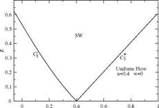
We consider the subdomain SW delimited by the C+ which bounds the uniform flow region where the perturbation velocity is (u1, 0) and the C— characteristic through the point of intersection of the former with the Ox-axis, Fig. 4.21.

Plane Flow

Подпись: CR+ Подпись: d dx Supersonic Flow Adjacent to Uniform Flow Region

In the case of plane, near sonic flow (M0 = 1), the compatibility relations given earlier are

Подпись: — |VY + 1 u2 — w ^ = 0 along C : (j^)C — = —Подпись: CR— : d1

(Y+1)u

(4.136)

We consider the change of independent variables from (x, z) to (£, Z) where £ = const along C + characteristics and Z = const along C— characteristics. One such transformation is given by

d £ — dx — /(y + 1)udz — dx + didz

/______ dZ (4.137)

d Z = dx + V (y + 1)udz = dxdx + f^dz

Let u(x, z) = U(£, Z) and w(x, z) = W(£, Z). Using the chain rule, the total derivative along the C + characteristic can be written

Supersonic Flow Adjacent to Uniform Flow RegionFig. 4.21 Subdomain SW adjacent to uniform flow region

Supersonic Flow Adjacent to Uniform Flow Region Supersonic Flow Adjacent to Uniform Flow Region

The CR+ now reads

This PDE can be integrated to give

Подпись: (4.140)2 3

– 3>/7+Тu3 + w = /(Z), Vz, Zin sw

where / is an arbitrary function of a single argument. Similarly, with CR one finds 2 3

Y + 1U2 + W = h(Z), V Z, Z in SW (4.141)

This last relation can be fully resolved by taking into account that all C – charac­teristics in SW emanate from the uniform flow region, therefore [2]

Axisymmetric Flow

The compatibility relations now read

2 / 3

— ~2 y + 1u2 + w

— 2 —y + 1u 2 —

Supersonic Flow Adjacent to Uniform Flow Region

CR+ ■ A.

CR ‘ dx


C+


CR-: d


C-


(4.145)

We will use the same change of independent variables and verify that a simple wave solution exists in SW by assuming that u(x, z) = U(Z), V Z, Z in SW. The C R+ now reads

2 3

-jVT+l U [3] [4] + W

Подпись:d W d w

= 2 = [w]c+ =——–

dZ dx z

This relation holds on a C + characteristic of equation Z = x — zV (Y + 1)U (Z) = const, hence one can write

d w dx

= — (Y + 1)U (Z) (4.147)

w x — Z

Upon integration one obtains ln |w| = —(t + 1)U(Z) ln |x — ZI + f (Z), where f is an arbitrary function of a single argument. Lets define the C— character­istic with parametric representation (xi(Z), zi(Z)) and characteristic Cauchy data (U(Z), W1(Z)) on C—. One finds

Подпись: (4.148)/zi(Z) (Y+1)U (Z)

W(Z, z) = W1(Z) ^ , along C+

-3 yytt u (Z)2 — W1(Z^

Supersonic Flow Adjacent to Uniform Flow Region

d

dx


Supersonic Flow Adjacent to Uniform Flow Region

The left-hand-side term can be expanded as

2 3

—3^гП и (Z)3 — w (Z, z)

Supersonic Flow Adjacent to Uniform Flow Region

Supersonic Flow Adjacent to Uniform Flow Region

d

dZ


which, upon integration, yields

– 3VYГГU(03 – W1 (0 ^ = h(Z) (4.152)

along the C – characteristic. Note that along a C-, z is only a function of £, not of Z. Making use of the fact that the C – originate in the uniform flow region, one concludes that h(() = const., and the relation becomes

2 3 3 z,(n Тїт+ЇЖО

дл/т+ї u 12 – U(03 – wm ^ = 0 (4.153)

Along the C – , the characteristic initial data cannot be chosen arbitrarily since

Подпись:|Vy + 1 ( u2 – U(02 ) – Wi(0 = 0 there. This completes the verification that

a simple wave solution exists in the SW subdomain. Although w(x, z) varies along C + characteristics, u(x, z) = U(£) is constant on a C+, implying that they are straight lines of slope. In this axisymmetric transonic small disturbance

approximation, a region adjacent to a uniform flow region is also a simple wave region.