Category Theoretical and Applied Aerodynamics

A Useful Nozzle Flow Solution

A Useful Nozzle Flow Solution A Useful Nozzle Flow Solution

The design of transonic nozzles can benefit from an exact solution of the TSD equa­tion that represents near-sonic flow conditions with a linear acceleration along the plane or axis of symmetry. Consider the two disturbance potential functions:

The reference Mach number has been set to M0 = 1. The first function satisfies the above TSD 4.78 (see also Cole and Cook [7]), whereas the second is a solution of the TSD equation for axisymmetric flow

Подпись:дф d2ф d2 ф 1 дф

– (1 + 1) 2 + 2 + = 0

dx dx 2 дz2 z дz

where z represents the distance from the axis of revolution. These solutions are similar and it will suffice to describe the flow features of one of them. The axisym – metric solution is more relevant to the design of a transonic nozzle for aerospace applications. The perturbation velocity field is given by

A Useful Nozzle Flow Solution

(4.123)


A Useful Nozzle Flow Solution

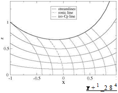
Some remarkable lines are the streamlines and the iso-Cp (or iso-u) lines. The first are obtained by numerical integration of the ODE

Подпись:dz Y + 1 . (Y + 1)2 3

= w = xz + z3

dX 2 16

using a fourth-order Runge-Kutta algorithm. This is an approximation, consistent with the small disturbance tangency condition. It is also possible to introduce a perturbation stream-function that satisfies

Подпись:дф дф дф y + 1

A Useful Nozzle Flow Solution

dx = ~pwz = “zdZ ’ dZ = puz = ~—z

Подпись:, , , Y + 12 (Y + 1) 3 (Y + 1)3 5

ф(х, z) = — X2z – xz3 – z5

2 6 40

Then, the streamlines of the solution can be more accurately obtained by solving Ф=p*a* ^z2 + ф(x, z)) =const. or for planar, 2-D flow Ф=p*a* (z + ф(x, z)) = const. The stream-function can be integrated simultaneously with the potential The Mach number is given by the linear relation

Подпись: (4.128)Y + 1

M (u) = 1 + u

The iso-Cp (or iso-Mach) lines are simply u = const. lines of equation

Y + 1 2

x = u – z2 (4.129)

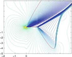
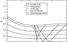
which are parabolae with axis along the x-axis where the tangent is vertical. The sonic line corresponds to u = 0 and passes through the origin. Note that the sonic line does not correspond to the nozzle throat. One streamline has been selected to represent the nozzle wall (thicker line), Fig. 4.15.

In the supersonic subdomain one can also calculate the characteristic lines. As mentioned, they admit a cusp on the sonic line. Note also that the “line of throats” corresponds to the minimum of each streamline and is given by w = 0, i. e.

Fig. 4.15 Streamlines and iso-Cp lines near a nozzle throat
Подпись: Y + 1 _2 8 4 (4.130)

A Useful Nozzle Flow Solution A Useful Nozzle Flow Solution Подпись: Y + 1 „ Zthroat Подпись: (4.131)

The radius of curvature R at the throat is an important design parameter. It varies with the streamline that is used as a nozzle wall and is found to be

Also, the C – characteristic that touches the sonic line on the x-axis is some­times called the “frontier of transonic flow” because any small perturbation made downstream of it does not affect the incoming flow. This is depicted in Fig. 4.16.

This solution is very accurate near the sonic line since the perturbation is vanish­ingly small there. It can be used to design a supersonic nozzle producing a uniform flow at Mach number M1. If the Mach number is too large to use the TSD equation, the solution can be matched and continued downstream of the frontier of transonic flow with the full potential equation to achieve an accurate design. For a low super­sonic Mach number, say Mi = 1.48, the small disturbance model is acceptable and the calculation can proceed readily as described below.
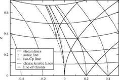
A Useful Nozzle Flow SolutionFig. 4.16 Characteristic lines and line of throats near a nozzle throat

Fig. 4.17 Characteristic initial value problem for a nozzle design providing a uniform flow u = u 1, w = 0
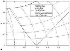
Подпись: x The following initial value problem will provide the design of a uniform super­sonic flow. Given M1 the corresponding value of u 1 is determined. With the choice M1 = 1.48 one finds u1 = 0.4. From the point (x1 = u1, 0) one draws the left­running C – characteristic along which the potential ф(х, z) as well as (u, v) are known from the exact solution, and the desired right-running straight C+ character­istic line of slope dz/dx = 1 /^J(j + 1)u1 that is bounding the uniform flow region of pertubation velocity (ui, 0) on its right side. On Fig.4.17, these characteristics have been superposed to the analytic solution developed earlier. The potential is also known along the C+ to be, by continuity, ф(х, z) = u1 x – u^/2. In the triangular region between these two characteristics, the characteristic initial value problem is well posed and a solution exists that will replace the analytical solution there. Note that the solution is integrated by marching perpendicular to the flow direction, for example using the method of characteristics.

The design is finalized by integrating the equation for the nozzle wall, starting from the point on the line of throats that provides the desired throat radius of curvature and marching in the flow direction until the C+ characteristic is reached.

Подпись: ф(x, 0) A Useful Nozzle Flow Solution A Useful Nozzle Flow Solution

Another approach consists in integrating the TSD directly, marching it away from the axis. This will be possible only in the supersonic subdomain. The first step will consist in setting up a Cartesian mesh system (for simplicity) with mesh points Xi = (i – 1)Ax, i = 1, ix, Zj = (j – 1)Az, j = 1, jx with for example Ax = 0.02, ix = 51 and Az = Ax/^J(j + 1)u 1. Initial and boundary conditions are specified on 3 sides of the domain, i. e.

Fig. 4.18 Initial-boundary value problem for a nozzle design providing a uniform flow u = U1, w = 0 and superimposed C+ and C – characteristics
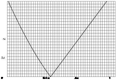
Подпись: 0 0.4 x Ax 1 See Fig.4.18.

A Useful Nozzle Flow Solution

The numerical scheme is an explicit, second-order accurate, centered scheme for фі, j+1 that reads

In order to initiate the marching procedure, two lines of data are needed. For j = 1 the values of the potential are given by фі,1 = xf /2, 0 < хі < x1 or

U2

фі,1 = u1 xi —2, x1 < xi < 1. The symmetry condition can be implemented simply by accounting for фі,2 = фі,0, where the index 0 corresponds to a fictitious lineat z = – Az, and for the limiting value of 1 фф (x, 0), which leads to the particular form of the scheme that can be solved for фі,2

, , .,фі+1,1 – фі-1,1 фі+1,1 – 2фі,1 + фі-1,1,

Подпись: 2 фі,2 - фі,1 , Az2 + Подпись: xi, 0 < xi < x1 0, x1 < xi < 1 Подпись: = 0 Подпись: (4.134)

-(7 + 1) +

The scheme is explicit and as such must satisfy a stability condition (CFL). How­ever, in contrast to the analysis of transonic flow in a given nozzle, the inverse problem of designing a transonic nozzle is much easier. This is due to the fact that the solution is marched in the direction normal to the flow. Stability is ensured because the most restrictive marching step Az corresponds to the highest value of the axial component of perturbation, here u = u 1, and the choice Az = Ax Д/(7 + 1)u1 is the maximum allowable value for the whole domain, according to the CFL criterion.

Before solving the design problem, the scheme was used to integrate that particular exact solution of the TSD equation to validate the scheme’s accuracy. The boundary conditions are in this case

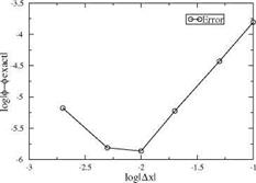
Fig. 4.19 Convergence of numerical scheme using exact solution
A Useful Nozzle Flow Solutionф(0, z) = z4, z > 0

ф(х, 0) = £, w(x, 0) = Щ(x, 0) = 0, 0 < x < 1 (4.135)

. ф(1, z) = 1 + z2 + z4, z > 0

corresponding to x1 = 1. The solution was calculated on several mesh systems with ix = 11, 21, 51 and 101 and compared with the exact solution, using as error norm є = maxi ф(і, jx) – фeXact(i, jx) where zjx = 1. On finer meshes such as ix = 201 or higher, round-off errors were dominating and the convergence test became meaningless. A convergence rate of approximately R = 2.0 was found. This is expected for a second-order accurate centered scheme. A convergence rate of 2.0 was also found for the planar solution. See Fig. 4.19.

The design of a nozzle producing a uniform supersonic flow at Mach number Mi = 1.48, i. e. corresponding to u = 0.4 is shown in Fig. 4.20. The initial-boundary value problem is discretized with a mesh of ix = 51 points. The slope of the C+ characteristic that bounds the uniform flow region is {dx)C + = = 1.02.

Hence Az = 1.02 Ax. The solution is marched 97 steps in z to approximately z = 1. The wall streamline passes through the throat at zthroat = 0.553, which gives the throat a radius of curvature Rthroat = 1.5 and an exit radius z1 = 0.608. The area
A Useful Nozzle Flow SolutionFig. 4.20 Design of a nozzle providing a uniform flow

U1 = 0.4, w = 0

ratio A1 = Z1 = 1.21, which is 4% larger than the value -4 = 1.16

Athroat Zthroat A

found in isentropic tables. This discrepancy is probably due to the small perturbation assumption, not the two-dimensional effect that places the sonic line in a larger cross section, upstream of the throat.

Murman-Cole Scheme

Murman-Cole Scheme Подпись: (4.115)

Murman and Cole introduced in 1970 a “type-dependent” scheme and a line relax­ation algorithm to solve the TSD equation. It was the first time that such a scheme was employed, in which different discretizations are used at subsonic points (centered) and supersonic points (upwind). Although they started from the conservative form of the PDE (Eq. 4.78), the first scheme did not conserve mass across a shock wave, resulting in jump conditions not being satisfied. The reason was that in the switching back of the scheme from an upwind – to a centered-scheme, a loss of conservation occurred. This was later corrected by Murman with a fully conservative four-operator scheme [3]. The sonic-point operator of Murman was revisited by Chattot [4] along with extension of the scheme to the solution of the equations of gas dynamics, a sys­tem of three first order PDEs. The four-operator scheme with the modified sonic point treatment is presented here. Lets assume for simplicity that the solution is sought on a Cartesian mesh system with uniform mesh steps Ax and Az. In this type-dependent scheme, one defines the local flow regime by comparing the x-component of the perturbation Ui, j with the sonic perturbation u *, where the “switches” are defined as

and the most recent values of the potential ф is used in the evaluation. (i) ui-i, j > u* and ui, j > u*, (supersonic point)

A few comments about the scheme: the shock-point operator is not consistent with the PDE but is conservative, which is more important (consistency is not defined when the solution is discontinuous). In the fully conservative scheme of Murman, the sonic-point scheme sets the x-derivative term to zero. Here the sonic point operator is consistent but not conservative, although the conservation error can be shown to be of order O (Ax). Note that the sonic-point operator is implicit via the coefficient

of the second derivative in x, not the second derivative in x itself (ФП+1 is in the

liJ

Murman-Cole Scheme Murman-Cole Scheme

bracket not in the second partial derivative). The latter can be written

The flow accelerates, hence, the coefficient of Ф+1 from the x-derivative term has the right sign and contributes to reinforcing the diagonal of the tridiagonal matrix.

Results are shown in Fig. 4.14 of the flow past a 10% thick Quasi-Joukowski airfoil of unit chord with leading edge at the origin of the coordinate system, at incidence a = 10 °, near sonic conditions. The mesh system uses stretching and extends from x = —2 to x = 5 and from z = -10 to z = 50. Red lines represent

Подпись: 5 4 3 2 1 Подпись: ^0Murman-Cole SchemeFig. 4.14 Iso-Mach lines of the near sonic flows: Top,
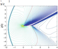
M0 = 0.9; Bottom,

Подпись: 1 2 x/c

Mq = 1.1

x/c

sonic lines. The pressure distributions on the profile for the two cases are very similar, as can be seen from the Mach lines near the airfoil. This is associated with sonic freezing. Indeed, behind the bow shock in the M0 = 1.1 flow case, the Mach number will be close to M1 = 0.9, which explains why the flow features near the profile are very similar.

Commercial jet aircrafts cruise at Mach number in the vicinity of M = 0.85. In such condition, the profile will see a fairly large supersonic bubble on the upper surface terminated, in general, by a shock wave. In order to mitigate the wave drag, supercritical airfoil sections have been developed by Whitcomb and Clark [5]. Super­critical profiles, also called “peaky” profiles, tend to have a blunt nose followed by a rapid change of slope and a fairly flat upper surface to achieve a moderate shock strength by limiting the maximum value of the Mach number in the supersonic region. Shock-free airfoils have also been developed with inviscid codes for which the super­sonic region is terminated by a smooth recompression. In practice, however, these shock-free airfoils may see a weak shock occur in place of the smooth transition from supersonic to subsonic, due to viscous/inviscid interaction as well as off-design flight conditions. For more details, see Boerstoel [6].

Forces and Moment

The nonlinearity of the governing equation does not allow for superposition of ele­mentary solutions nor the decomposition of the problem into a symmetric and lifting problems. However, the symmetric problem still has zero lift and moment, but wave drag may occur when supersonic regions are present in the flow.

The lift is given by the integral seen earlier

Q = j (c~p (x) — C+ (x)) ddx = J {2u+(x) — 2u — (x)) ddx =

Forces and Moment Forces and Moment
Подпись: 2

This result is consistent with the Kutta-Joukowski lift theorem. The drag is also calculated as before

Подпись: to obtain Forces and Moment Forces and Moment

One can substitute the following expressions from the tangency conditions

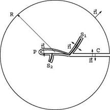
Another approach to evaluating the drag is based on the x-momentum theorem applied to a control volume with exterior unit normal, whose boundary Sfi is made of a large circle of radius R, connected by a cut C to the profile P and shock(s) Sk that are excluded, see Fig.4.13. Inside the domain bounded by Sfi, the flow is smooth. Application of the divergence theorem to the x-momentum Euler equation leads to the contour integral

Forces and MomentFig. 4.13 Contour for evaluation of the drag integral

On the circle R, the perturbation velocity (u, w) decays as R resulting in

no contribution. Along the profile P the contribution is precisely the drag force D’. Along the cut C the flow is continuous and again no contribution will occur, but along the shock(s) Sk the flow is discontinuous. For the full Euler equations, though, there would be no net result from the shocks, because the jump conditions would be satisfied there and more precisely

< p(V. Vt) >= 0, < pU(1 + u)(VV) + pnx >= 0 (4.97)

from conservation of mass and x-momentum. This is no longer true when the solution is approximated by its leading terms (u(1),w(1)). The only two non zero contributions are therefore along the profile and along the shock(s).

4

Mass and momentum are conserved to second order (O (e 3)), but to third order this is no longer the case. Indeed, expanding the conservation of mass and x-momentum to third order gives

e2 {!(Ku(2) + p(3) + u(1)p(2) + p(1)u(2)) + !(w(2) + p(1)w(1))} = 0 e2 {! (Ku(2) + p(3) + 2u(3) + p(3) + 2u(1)p(2) +

2p(1)u(2) + 2u (1)u(2) + p(1)u(1) 2)

+ д (w(2) + p(1)w(1) + u (1)w(1))} = 0

(4.98)

Subtracting the first equation from the second yields a combined mass-momentum equation

Подпись: 2

Forces and Moment Forces and Moment Подпись: (4.99)
Подпись: dxdz =
Подпись: (4.96)

_(u(3) + p(3) + u(1)p(2) + p(1)u(2) + 2u(1)u(2) + p(1)u(1) 2)

Подпись: 2 Forces and Moment

Upon replacing p(1) and p(2) from previous results, this reduces to

Forces and Moment

The last term in the ^-derivative is of higher order and can be removed, while the

Forces and Moment Подпись: =0 Подпись: (4.105)

This equation is equivalent to the previously derived governing equation for smooth flow, since it can be written as

However, when the flow is discontinuous, such as at a shock, the solution (u(1), w(1)) to the low order governing equations does not satisfy the jump conditions associated with this new conservation equation. In fact, the mass and x-momentum are not conserved at third order. This is consistent with the fact that the flow is irrota – tional to the first two orders but not to third order. Hence drag appears at third order (O (e2)). If we revert to the physical variables, the drag reads

D = pU2 < (1 – m0) – Y + m+ 3 – nx + uw nz > dl (4.106)

Jsk 23 2

where Sk represents the shock line(s) with arc length l and + is the normal unit vector to Sk oriented in the flow direction. This determines how the jump is calculated, i. e. downstream values minus upstream ones. Here we have used the combined mass – momentum equation. The reason for using this equation is that mass is not conserved
to third order, therefore, this imbalance will add momentum in the flow direction in the amount corresponding to < pU(V. it) > which must be subtracted from the x-momentum given by < pU(1 + u)( V. it) + pnx >.

The above expression for D’ can be simplified further by using the shock con­ditions derived earlier. As a first step, one eliminates the nz component from the irrotationality condition

< w >

nz = nx (4.107)

<u>

Подпись: (1 Forces and Moment

we also make use of the identities < a2 >= 2a < a > where a = a1+a2 is the average value across the discontinuity, < ab >= a < b > +b < a > and < a3 >= (a2 + 2a2) < a >. The jump term in D’ now reads

Forces and Moment Подпись: nx = 0 Подпись: (4.109)

The final step consists in using the shock polar relation multiplied by <— nx and subtract it from the above equation

One finds the following result

Подпись: (4.110)Подпись:Y + 1 2 2 2_ 2

M2(u2 + 2u ) < u > + (y + 1)M^u < u >

This can be rearranged to read

— YITM2 < u >3 nx (4.111)

The drag is thus

D = — MlpU2 < u >3 nxdl

12 Jsk

or the drag coefficient

Y + 1 2 3 dl

Cd — – м2 < u >3 nx— (4.112)

6 4 c

This makes it clear that if there are no shock waves in the flow, the wave drag is zero.

Forces and Moment Подпись: Cp (x))xdx Подпись: pU2 Forces and Moment Подпись: u (x))xdx, ^
Forces and Moment

The moment is obtained from

Подпись: (4.113)M, o = – pU2 ^ xdx

Forces and Moment Подпись: 2 U Подпись: fc г'x) id~x 0 c c Подпись: (4.114)

and the moment coefficient

Boundary Conditions

Подпись:The boundary conditions associated with the TSD equation the linear models:
= U (f ‘±(x) – a)

Vф(x, z) ^ 0, x2 + z2

Note that the tangency condition is applied on the x-axis, which is consistent with the small disturbance assumption. For a lifting airfoil, the Kutta-Joukowski condition reads

Г'(с) = U < u(c, 0) >= U(u(c, 0+) – u(c, 0-)) = 0 (4.83)

where r(x) = U < ф(x, 0) >= U(ф(x, 0+) – ф(x, 0 )) represents the circulation distribution inside the profile.

4.1.2 Jump Conditions

The TSD is written as a system of two first-order PDEs in conservation form.

The jump conditions are given by

Подпись:

Boundary Conditions

< (1 — M^)u — m02u2 > nx + < w > nz = 0

< w > nx — < u > nz = О

Подпись: < (1 — M2)M Boundary Conditions Подпись: О Подпись: (4.86)

Upon elimination of n = (nx, nz), the unit vector normal to the jump line, the shock polar is obtained

The term in the first bracket can be written differently by using the identity < u2 >= 2u < u > where U = (u1 + u2)/2 represents the average value of u across the shock. This results in

^1 — M^ – (y + 1)M2u) < u >2 + < w >2= 0 (4.87)

Given the upstream state (u1,w1), if u < u*, the term in the bracket is positive and the only solution is the trivial solution < u >=< w >= 0. No jump is allowed and (u2, w2) = (u1; w1). The flow is locally subsonic. If u = u*, < w >= 0. This corresponds to a smooth transition through the sonic line if < u >= 0, or to the normal shock which does not deviate the flow since w2 = w1, if < u > = 0.

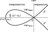
If u > u*, two solutions exist < w >= ±J(y + 1)M^yu1 – u* + < u >

Подпись: I < w > max Подпись: 4 3V3 Подпись: (Y + 1) M2(u 1 Подпись: u*) 2 Подпись: (4.88)

corresponding to the two branches J + and J – of the polar. The maximum flow deviation through a shock occurs when < u >= 4(u* – u1)/3 and is given by

The shock polar is depicted in Fig.4.11.

The slopes of the shock waves in the physical plane are given by

Подпись:(dz ___________ 1___________

dx’J + ,J(y + 1)М2ум1 – u* +

Подпись:dz 1___________

dx’J – J(y + 1)M0yu 1 – u* + <2>

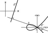
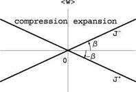
Note that the slopes of the lines that connect the downstream states to the double point O on the shock polar are perpendicular to the images of the shocks in the physical plane. In the limit of infinitely weak shocks, the tangents to the double point O are perpendicular to the characteristic lines representing them, Fig. 4.12.

Подпись: <u>Boundary ConditionsFig.4.11 TSD polar

Boundary Conditions

Boundary Conditions

Fig. 4.12 Polar in hodograph plane and shock in physical plane

Transonic Small Disturbance Theory

4.1.1 Governing Equation

Assuming inviscid, steady, 2-D flow of perfect gas, the Euler equations are perturbed about a uniform flow near Mach one. In this section for practical reasons, we will use dimensionless perturbation velocity components (u, w) defined as

Vx = и (1 + u), Vz = U w (4.55)

where ~V is the total velocity. With this notation, the Euler equations read

dpU(1+u) , dpUw 0

Transonic Small Disturbance Theory Подпись: (4.56)
Подпись: dpU 2(1+u)2+p , dpU 2(1+u)w 0 d x + dz = 0

dx + dz = 0

Note that the energy equation has been replaced by the constant enthalpy condi­tion, valid for isoenergetic flows, even when shocks are present. For a thin airfoil of vanishing camber, thickness or incidence of order є ^ 1, the flow dependent variables are expanded as

p = P0 (1 + є3 p(1) + є3 p(2) +—— )

U (1 + u) = U (1 + є3 u(1) + є 3 u(2) + •••) (4 57)

U w = U (єж(1) + є 3 w(2) + ■■■)

. p = P0 + P0U 2(є3 p(1) + є3 p(2) +——– )

In order to obtain a mixed-type equation in a transformed plane (£ = x, ( = є 3 z), it has been shown that one needs to assume that, as є ^ 0, the Mach number approaches unity, i. e. 1 – M2 = O (є3).

One starts with evaluating the following groupings:

pU(1 + u) = p0U ^1 + є3(p(1) + u(1)) + є3(p(1)u(1) + p(2) + u(2)) + ■■■ ^
pUw = p0U ^w(1) + є3 (p(1)w(1) + w(2)) + ■■■
pU 2(1 + u)2 = p0U2

x (1 + є3 (p(1) + 2u(1)) + є4 (2p(1)u(1) + u(1)2 + p(2) + 2u(2)) + ■■■) pU2(1 + u)w = p0U2 ^w(1) + є3(p(1)w(1) + u(1)w(1) + w(2)) + ■■■ ^ pU2w2 = p0U2 (є2w(1)2 + ■■■)

When these expressions are substituted in the Euler equations, at the lowest order one finds the following results.

Подпись: 2 є 3 Подпись: d p1+u'1) dZ Подпись: = 0 Подпись: (4.59)

For conservation of mass:

Transonic Small Disturbance Theory Transonic Small Disturbance Theory Подпись: =0 Transonic Small Disturbance Theory

For the x-momentum:

The first two PDEs can be integrated as

p(1> + u(1> = F (Z >, p(1> + 2u (1> + p(1> = G (Z > (4.62)

where F and G are arbitrary functions of Z. However, since the perturbations vanish at infinity for all values of Z, F = G = 0. Hence p(1> = —u(1> and p(1> = – u(1>. The z-momentum equation yields a first PDE for (u(1>, w(1>), so that we now have

‘ dw(1> du(1> _ n

Щ—– ЇЇТ = 0

p(1> = —u (1> (4.63)

p(1> = —u(1>

The PDE states that the flow is irrotational at order one, i. e. there exists ф(1> (Z, Z> such that Vф(1> = (u(1>, w(1>). In order to find a second PDE for (u(1>, w(1>), we need to carry out the expansions to the next order for the PDEs and for the equation of constant enthalpy. Consider first the enthalpy equation. To lowest orders one finds

Подпись: 7 P0 Y — 1 P0Подпись: (4.64) (4.65) U 2

+ ^ = Я0

є2 – y—ї (y m02 p(1> — p(1> + (y —1> m2 u (1>}

Transonic Small Disturbance Theory Подпись: 4 O (Є -3 >
Transonic Small Disturbance Theory

where we have made use of a2 = yp0/p0 and M0 = U/a0. When p(1> and p(1> are eliminated in terms of u(1>, the terms do not balance to zero, but there remains

since, by hypothesis, (1 in the expansion. Let


m2) = O (e 3). This remainder is added to the next term


Transonic Small Disturbance Theory

(4.67)


Transonic Small Disturbance Theory

K is of order unity and is called the transonic similarity parameter. It is defined up to a multiplicative factor Mg, к > 0. Two definitions are commonly used:

K = 1—M0, (Cole)

1-M23 (4.68)

K =——- 0, (Spreiter)

M2 e3

Transonic Small Disturbance Theory Подпись: (4.69)

At the next order we now obtain

The right-hand-side must be O(e2) or higher. Again, eliminating p(1) and p(1) in terms of u(1) yields for the unknowns of the level 2 approximation:

Ym2p(2) – p(2) + (y – 1)M2u(2) + Ku(1) + (1 – YM2)u(1) 2 + —1 M2u(1) 2 = O(e3)

(4.70)

Returning now to the conservation of mass and x-momentum

‘ e4 (d(p"u"> + p(2> + u(2)) + ) = 0 (471)

e q | (2p(1)u(1) + u(1) 2 + p(2) + 2u(2) + p(2)) + = 0 )

Подпись: d (u(2) + p(2)) Подпись: =0 Подпись: (4.72)

Subtracting one from the other and substituting p(1) = – u(1) yields

which can be integrated to give p(2) = —u(2). Now, solving the energy equation for p(2) in terms of u(2) and first-order terms provides the following result:

p(2) = – M^u{T) + Ku(1) + ^1 – M02) u(1)2 + O(e2) (4.73)

Подпись: 4 є 3 Подпись: (1 Подпись: M2)u(2) + Ku(1) Подпись: Y+1 M2u(1) 2 + O (є 2) Transonic Small Disturbance Theory Подпись: = 0

Final substitution of these expressions in the first PDE above, reduces it to

(4.74)

Note that the first and last terms in the inner bracket are of higher order and can

4

Подпись: 4 Є 3 Transonic Small Disturbance Theory Transonic Small Disturbance Theory Подпись: dw(1) + =0 Подпись: (4.75)

be dropped to give at O (є 3):

In the second-order approximation, the level-2 unknowns p(2), u(2), w(2) and p(2) do not appear, but the nonlinear contribution involving level-1 unknowns remains.

Reverting to the physical variables (x, z), with Cole’s definition of the tran­sonic similarity parameter, the results are the following for the velocity, density and pressure:

U (1 + є2 u(1)) = U (1 + u)

U єю(Г) = U w

2 m (4.76)

P = po(1 + є3p(1)) = po(1 – u)

. p = Po + PoU2є3 p(1) = po – poU2u

Transonic Small Disturbance Theory

Note that now Cp = —2u. The governing equations for (u, w) read

Подпись: (1 — Mo2) Transonic Small Disturbance Theory Подпись: д2 ф д2ф 9X 2 + 9Z2 ^ Подпись: (4.79)

called the Transonic Small Disturbance equation (TSD). In non-conservative form, it reads

Let u* = (дф/дx)* = (1 — m2)/ ((j + 1)M2) represent the critical pertur­bation velocity. The TSD equation is a nonlinear equation of mixed-type. When u = дф/дx < u*, the equation is of elliptic type, which corresponds to subsonic
flow. When u = дф/д x > u*, the equation is of hyperbolic type, which corresponds to supersonic flow. The sonic line is given by u = дф/дx = u*.

The linearized Mach number-u relation is given by

u Y + 1 2

M(u) = M0 + (1 – M0)— = M0 + ^—M^u (4.80)

u* 1 + M0

In the supersonic subdomain, characteristic lines exist. The rigorous full theory of characteristics is beyond the scope of this book (see Appendix C2 for a brief introduction). For further information the reader is referred to Courant and Hilbert, Ref. [1], or also to JJC, [2].

The slopes of the C + and C – characteristics can be found to be:

/ dz_ ________ 1_______ / dz __________________ 1_______

dx’C+ У (y + 1)M02 ju-v*’ dx)c – J(y + 1)

(4.81)

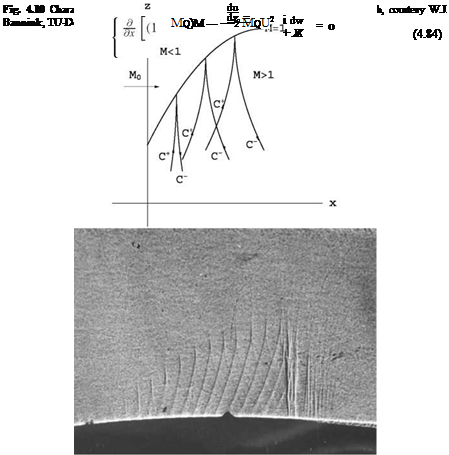
The slopes of the characteristic lines vary with the local value of u and their shapes depend on the solution. Note that their slopes are infinite at the sonic line, Fig.4.10. In the lower part of the figure, a visualization of the characteristic lines was obtained fortuitously when pieces of tape were placed on the profile to cover the pressure taps.

Limit of Validity of Linearized Theories

The above linear theories all fail when the incoming Mach number approaches unity. Indeed, the Prandtl-Glauert correction shows a dependency of the local and global coefficients with incoming Mach number through the multiplication factor

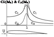
1 /^J1 – m2, whereas, the linearized supersonic flow theory shows the correspond­ing dependency through the factor 1ЦM2 – 1. In both cases, the solution becomes infinite at M0 = 1. This is in contradiction with experiments that indicate, for exam­ple, that the lift and drag coefficients are finite and reach a maximum near M0 = 1. In graphic form, this is shown in Fig.4.9.

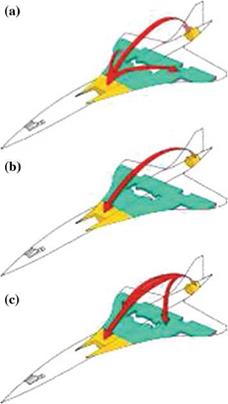
Fig. 4.8 Fuel pitch trim. a trimming fuel during transonic acceleration b trimming fuel during supersonic cruise c trimming fuel during transonic deceleration (from https://en. wikipedia. org/wiki/File: Concorde_fuel_trim. svg Author: steal88)

Limit of Validity of Linearized TheoriesПодпись:Fig. 4.9 Linear theories and nonlinear transonic results near M0 = 1
The linearized potential equation does not allow for continuous description of flow fields from subsonic to supersonic flow regimes. In particular, it cannot represent flow fields in which regions of supersonic flow coexist with regions of subsonic flow, called mixed-type flows. Such complex flow fields, which may include sonic line, expansion wave and shock wave, require a mixed-type equation, one that is elliptic in regions of subsonic flow and hyperbolic where the flow is supersonic. In order to change type, such an equation has to be nonlinear. It will be presented in the next section. Note that near Mach one, the aerodynamic coefficients, as given by the nonlinear theory, reach an extremum. This is called “sonic freezing.”

Center of Pressure

Let D be an arbitrary point along the chord, the moment at D reads

Подпись:xd / a

Cm, D — Cm, o + Cl — (Cm, o)^_0 – 2 + 4

Setting the result to zero gives the location of the center of pressure, i. e.

xc. p. = 1 _ в (Cm, o)a=0 = 1 + 1 fC <m dx (4 53)

c 2 4a 2 a 0 c c

In general, the center of pressure will go to when a goes to zero, and will be close to the mid-chord for large incidences.

Application:

• location of the center of pressure for a flat plate and symmetric profiles: Xcc~ = 1

• location of the center of pressure for a parabolic plate of camber <: = 1 _

2 d 1

3 c a’

4.5.1 Aerodynamic Center

Taking the partial derivative da of Cm, D and setting the result to zero, gives the location of the aerodynamic center, that is

Подпись:xa. c.

c

this is in sharp contrast to subsonic flow, where the aerodynamic center is located at the quarter-chord. This phenomena has been responsible for many accidents in the early days of supersonic flights. The Franco-British Concorde transport aircraft was handling the change of location of the aerodynamic center, during the transonic acceleration, by moving fuel from a tank located in the front fuselage area to a tank located in the tail area of the fuselage and doing the reverse for return to subsonic and landing, Fig.4.8.

Moment

The moment about the leading edge is given by

Подпись: dM o — -x

xdFz — -1 pU2 (cp (x) – C + (xxdx

Moment

(4.49)


Using again Ackeret results, the moment coefficient can be written

2 c /_ /, x dx

Подпись: ccCm, o — (f (x) – a + f +(x) – a)-

0

c / / x dx

(f (x) + f +(x))

0 c c


a2 – 2- + –

в в


(4.50)


Let (Cm, o) 0 be the integral term. Introducing camber and thickness reduces the


equation to


Moment

4 c d (x) dx в 0 c c


4

в


(4.51)


Moment

Moment

where we have performed an integration by parts and used d(0) — d(c) — 0. The integral represents the dimensionless area under the camberline. It is worth noting that, although lift does not depend on camber, the aerodynamic moment in general does.

Application:

• moment coefficient of a flat plate or symmetric profile: Cm, o — -2^

• moment coefficient of aparabolic plate of camber d; Cm, o — -2 ^-35 d.

Forces

The force contribution per unit span is given by

Подпись:d~F’ = -2pU2 (c-(x)(rtdl)- + C+ (x)(tdl}+) (4.43)

Подпись: Fig. 4.7 Schematic for calculation of forces Forces Forces Подпись: c

where (itdl) = (dz, – dx) and (itdl)+= (-dz+, dx), see Fig. 4.7.

The lift corresponds to the z-component of the force, i. e. dL’ = 1 pU2 (c~ (x) – C+ (x}) dx ^ dCi = (c~ (x) – C+ (x)) у (4.44)

With the help of Ackeret formulae, one finds

2 c, !, dx a

Ci = (a – f -(x) + f + (x) – a)— = 4- (4.45)

P 0 c P

where we accounted for f ±(0) = f ±(c) = 0. The result is remarkable in that, contrary to what happens in subsonic flow, camber does not contribute to lift.

The drag is the x – component with

dD’ = -2pU2 (є-(x)dz – – C+ (x)dz+) ^

dz, dz+ dx

dCd = – C-(x)— – C + (x)— – (4.46)

Again, using Ackeret formulae, one can evaluate an inviscid drag which is called the “wave drag” with coefficient given by

Cd = 2 ^ ((f ‘-(x) – a)2 + (f’+ (x) – a)2) ^2

= 4 + (f -(x))2 + (f +(x))2 (4.47)

в в 0 c

Let (Cd)a=0 be the integral term in the above equation. Introducing camber and thickness, it can be rewritten as

Подпись: 4Подпись: (Cd )a=0Подпись: вForces(4.48)

The result shows that in supersonic flow, camber, thickness and incidence, all contribute to wave drag.

Application:

2

• drag coefficient for a flat plate: Cd = 4 5

• drag coefficient for a biconvex profile of thickness |: Cd = 45+35 (§)2

• drag coefficient for a parabolic plate of camber d: Cd = 4 5+35 (4- )2

Note, that in linearized supersonic flow theory, the flow at the leading edge of the profile is still governed by a wave-type hyperbolic equation and the upper and lower surfaces do not communicate. Hence, the flow does not go around the leading edge as it does in subsonic flow, and there does not exist a suction force.

Jump Conditions: Shock and Expansion Waves

The jump conditions associated with the system of first-order PDEs

Подпись: (4.39)I a – m?) du + dw =0

dw ди

Подпись: are found to be Подпись: (1 — M?) < и > nx + < w > nz = 0 < w > nx — < и > nz = 0 Подпись: (4.40)

dX — д = 0

where n = (nx, nz) is a unit vector normal to the jump line. Upon elimination of the normal vector, the shock polar is obtained:

(M? — 1) < и >? — < w >?=

— 1 < и > + < w >^ — 1 < и > — <w>^ = 0 (4.41)

The shock polar is made of two straight branches in the hodograph plane (< и >, < w >), J+:@ < и > + < w >= 0 and J—:в < и > — < w >= 0, see Fig.4.5. The origin of the hodograph plane corresponds to infinitely weak waves, i. e. characteristic lines, the half-plane < и >< 0 represents shock waves and the half-plane < и > 0 represents expansion waves.

The slope of the jump lines J+ and J— in the physical plane are obtained by selecting a root and using one of the jump relations

dz nx < и >

dx nz < w >

(dz) = 1 = (dz) , (dz) =—1 = (dz) (4.4?)

dx J+ p dx C+ dx J — p dx C—

Подпись: <u>Jump Conditions: Shock and Expansion WavesFig. 4.5 Shock polar for linearized supersonic flow
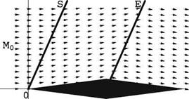
Fig. 4.6 Supersonic flow past a double wedge. S is a shock, E is an expansion “fan”

Подпись: zПодпись: XJump Conditions: Shock and Expansion WavesNote that in linear theory the jump lines coincide with the C + and C – characteris­tics, Fig.4.4, and are perpendicular to their images J+ and J – in the hodograph plane, respectively. Shockwaves as well as expansion fans are represented by characteristics lines across which the velocity vector is discontinuous. Shocks can be differentiated from expansion waves by the fact that the u -component decreases (pressure increases) across them when following a particle, whereas the u-component increases (pressure decreases) as a particle crosses an expansion line. Figure4.6 depicts the flow past a double wedge profile at zero incidence. Note also, that in linear theory, an expansion fan collapses on a single characteristic line which acts as an “expansion shock.”