Category Theoretical and Applied Aerodynamics

Linearized Supersonic Flow

Let в — M2 – 1, when M0 > 1. The potential equation for linearized supersonic

flow is of hyperbolic type and models wave propagation. It is analogous to the wave equation that models the vibrations of a string. The PDE and boundary conditions read:

Подпись: -вПодпись: 2д2Ф , д2Ф dx2 + dz2

Linearized Supersonic Flow Подпись: (4.22)

—0

ф(х, z) ^ 0, x2 + z2 ^ to, almost everywhere

The general solution of the PDE, the d’Alembert solution, is given by

ф(х, z) — F(x – ez) + G(x + ez) (4.23)

where F(ф) and G(Z) are arbitrary functions of a single argument. These unknown functions are uniquely determined by the boundary conditions. It is easy to verify

Linearized Supersonic Flow

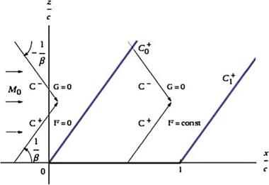
Fig. 4.4 D Alembert solution for the upper surface

that such a solution satisfies the PDE with any functions F and G. The families of straight lines, £ = x – pz = const. and Z = x + pz = const. are the characteristic lines of the PDE. They represent, in this approximation, wave fronts of infinitesimal perturbations as well as shocks and expansion waves of finite strength. They have slopes dz/dx = ±1/p.

Consider a profile placed along the x-axis, 0 < x < c. The supersonic flow is from left to right. Upstream of the profile leading edge the flow is undisturbed. Perturbations will occur downstream of the two characteristics passing through the origin. Consider first the upper surface. The C+ characteristic through O and C+ through the trailing edge delimit a semi-infinite strip where the perturbation due to the profile affects the flow solution, see Fig.4.4.

The solution will be obtained once the expressions for F and G are found. In the undisturbed flow region, upstream of the C0+ characteristic, the solution for the perturbation potential is ф = const. = 0 (the potential is defined up to an arbitrary constant). In other words:

F(x – вz) + G(x + pz) = 0, Vx, z, z > 0, £ = x – pz < 0 (4.24)

which implies that F = G = 0. Furthermore, since G remains constant along the Z = x + pz = const., G = 0 in the semi-infinite strip 0 < £ = x — pz < c. The solution there reduces to ф(x, z) = F (x — pz). In order to apply the tangency condition, one needs to calculate the ш-component along the x-axis. It is

дф(x, z) , дф(x, 0+) , /,

= F (£)(—p) ^ =-pF'(x) = U(f +(x) – a) (4.25)

dz dz

Подпись: F (x) Подпись: U , в(f+(X) Подпись: ax) + const. Подпись: (4.26)

The last equation can be readily integrated as an ODE to give

Finally, the constant is found by enforcing continuity of the potential at x = 0, hence the constant is zero. The above equation defines the functional form of F. Replacing x with £ extends the definition of ф from the axis to the semi-infinite strip as

ф(x, z) = – U (f + (x – вz) – a(x – вz) , z > 0, 0 < £ = x – вz < c (4.27)

Linearized Supersonic Flow Linearized Supersonic Flow

Note that, above the airfoil, the solution is only a function of £ = x – вz. It is also easy to see that the tangency condition for w(x, 0+) is satisfied. There remains to calculate the u-component on the profile and the pressure coefficient. The former is now obtained:

Proceeding in a similar way, one would find that, below the profile, the potential is ф(x, z) = G(x + pz) (i. e. F = 0 for z < 0, 0 < Z = x + вz < c) so that, upon satisfying the tangency condition w(x, 0-) = U(f -(x) – a), the perturbation potential is found to be

U

Linearized Supersonic Flow Linearized Supersonic Flow

ф(x, z) = в (f (x + вz) – a(x + вz)), z < 0, 0 < Z = x + вz < c (4.30) The u-component of velocity on the profile is now

The expressions for C± (x) are known as Ackeret formulae.

Note that there was no reference to a Kutta-Joukowski condition, even when there is circulation and lift. Indeed, due to the wave character of supersonic flow, the

solution, hence the forces and moment on the profile, do not depend on the solution downstream of the trailing edge. It is interesting, however, to discuss the solution downstream of the profile. At the trailing edge the potential is discontinuous. Indeed, the solution in the two semi-infinite strips above and below the profile reads:

Г ф(х, z) = – Ц (f +(x ~ вz) – a(x – f3z)), z > 0, 0 < £ = x – f3z < c

ф(х, z) = Ц (f -(x + вz) – a(x + вz)), z < 0, 0 < Z = x + ez < c

(4.33)

At the trailing edge the jump of potential is < ф(с, 0) > = ф(с, 0+) – ф(с, 0-) = Г (с) = 2вас. The potential function for a lifting problem is multi-valued and a cut is introduced to regularize it. Although it could be any line £ > с, я > с, originating at the trailing edge, it is convenient to align the cut with the x-axis. The cut does not represent a physical surface, streamline or wall, therefore pressure and velocity are continuous across it. The continuity of pressure or u(x, z) is simply r'(x) =< u(x, 0) >= u(x, 0+) – u(x, 0-) = 0, x > с. This condition can be integrated along the x-axis from x = с to give < ф(x, 0) >= ф(x, 0+) – ф(x, 0-) = Г (с).

The same result can be obtained when the cut is an arbitrary line. Above the cut the solution is still of the form ф(x, z) = F(x – ez), whereas below the cut it is of the form ф(x, z) = G(x + вz). The condition along the cut is therefore

F (x) – G(x) = Г (с) (4.34)

The continuity of the ш-component leads to

дф(x, 0+) , дф(x, 0-)

= – вF (x) = = вG (x), ^ F (x) + G'(x) = 0 (4.35)

dz dz

This last ODE can be integrated to give

F (x) + G(x) = соті. = 0 (4.36)

where the constant is obtained for x = с. From these conditions the solution for F and G is obtained:

Подпись:F = сон8і. = Цсї G = wnsi. = – r2f)

The solution reads

ф(x, z) = Цвас, z > 0, с < £ = x – вz
ф(x, z) = —Цвас, z < 0, с < Z = x + вz

The flow field, downstream of the profile is the uniform, undisturbed flow V =

(U, 0).

Prandtl-Glauert Transformation

In subsonic flow, M0 < 1, the linearized potential flow equation is elliptic and the Prandtl-Glauert transformation reduces it to Laplace equation. Let в = – J 1 – m2 and define new dependent and

transformation and the solution to this problem is equivalent to solving for the incompressible flow past the same airfoil. For this reason, except for a finite number of singular points such as leading edge and other sharp edges, the subsonic compressible flow solution past a profile is smooth and does not admit lines of discontinuity.

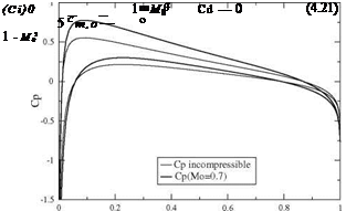
Prandtl-Glauert Transformation Подпись: ^1 дф(х, 0) 1 C U в дх в 0 Подпись: (CP) 0 V1 - M02 Подпись: (4.20)

Let the subscript 0 represent the incompressible solution, i. e. at Mach M0 = 0. The pressure coefficient is modified as follows

Prandtl-Glauert Transformation Prandtl-Glauert Transformation

where (Cp)0 = -2j, see Fig.4.3. The forces and moments at Mach number M0 will also be divided by 1 – M2, which is the Prandtl-Glauert rule

Note that the drag is still zero. To be complete, one can add that the center of pressure and the aerodynamic center coincide with their incompressible counterparts.

Linearized Compressible Flow Potential Equation

Подпись: P_ P0 Linearized Compressible Flow Potential Equation Подпись: (4.6)

As before, we will assume that the uniform flow is only slightly disturbed by a thin airfoil at incidence, where the incidence is also a small parameter, a ^ 1. The above density-velocity relation can be expanded for small values of u and w to read

Linearized Compressible Flow Potential Equation Linearized Compressible Flow Potential Equation Подпись: (4.7)

The relative change in density is a more meaningful number and takes the form

which states that the Mach number is an amplification factor of the compressibility effects: the larger the Mach number, the larger the relative changes in density for a given longitudinal perturbation in velocity. Note that the incompressible limit is recovered for M0 = 0. The changes in density are considered negligible when M0 < 0.3. On the other hand, when M0 > 0.3, compressibility effects are expected.

The linearized Cp can also be derived from the density-velocity relation. Fist notice that the pressure ratio of local pressure to the undisturbed pressure is to first order

Подпись: P_ P0 Linearized Compressible Flow Potential Equation(4.8)

Linearized Compressible Flow Potential Equation Подпись: (4.9) Подпись: Cp = -2

and using the identity ip0M^ = p0U2, simplifies the pressure coefficient to read, as before

in compressible, 2-D flow.

The tangency condition is also unaffected by the changes in density and remains

w(x, 0±) = U (f ‘±{х) – a) (4.10)

The equation of conservation of mass is nonlinear. The last step is to linearize it using the result just obtained for the density. The mass flux components are expanded as

p(U + u) = P0 (1 – M2U) U (1 + u) = poU (1 + (1 – M2)U + …) pw = P0U (w + )

(4.11)

where the second and higher order terms have been omitted. Substitution in the mass conservation yields a linear system of two first order PDEs

2 du dw

M0 Ш + dz = 0

(4.12)

dw du dx dz 0

(4.13)

Подпись: (1 Подпись: 2 d2ф д2ф dZX + a? =0 Подпись: (4.14)

The irrotationality condition allows to introduce a velocity potential for the per­turbation velocity such that u = ^ and w = ддф. The conservation of mass is transformed into a second order PDE

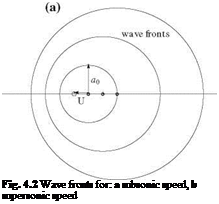
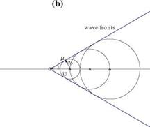
Подпись: Fig. 4.2 Wave fronts for: a subsonic speed, b supersonic speed
Linearized Compressible Flow Potential Equation

called the subsonic linearized compressible flow potential equation when M0 < 1 and the potential equation for linearized supersonic flow when M0 > 1. The change of sign of the coefficient 1 – M0 is significant in associating different physical phenomena with different equation types, elliptic for subsonic flow with perturbation decay in all directions, and hyperbolic for supersonic flow with subdomains separated by wave fronts. This can be illustrated by a moving source emitting sound waves at equal intervals and examining the development of the wave fronts for Mach number aU < 1 and aU > 1, Fig.4.2. In subsonic flow, the waves move away from the source and the source influence is felt everywhere. The perturbations of the supersonic source are confined within a wedge (a cone in 3-D).

In supersonic flow, the wave fronts admit envelopes which make an angle j, called the Mach angle, with the flow direction. It is easy to see from Fig.4.2 that the Mach angle is given by

Подпись:Подпись:(4.15)

Governing Equations

Assuming 2-D, steady, inviscid and irrotational compressible flow with uniform con­ditions at infinity, the governing equations of conservation of mass, the irrotationality condition and energy equation (generalized Bernoulli) read in terms of the perturba­tion velocity components (u, w) © Springer Science+Business Media Dordrecht 2015

J. J. Chattot and M. M. Hafez, Theoretical and Applied Aerodynamics,

DOI 10.1007/978-94-017-9825-9_4

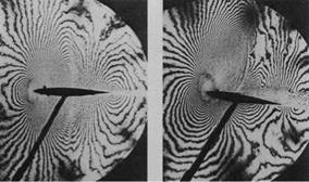
Fig. 4.1 Holographic interferometry of transonic flow fields, (from history. nasa. gov)


dp(U + u) | dpw 0 dx + dz

(4.1)

dw du dx dz ^

(4.2)

Y p V 2

+ = H0 = const. (Y – 1)P 2 0

(4.3)

where y = cr is the ratio of specific heats, ~V = (U + u, w) the total velocity and

cv

Ho is the uniform stagnation enthalpy for isoenergetic flow. The entropy for such flows is uniform and can be written

p p o

= Y = const.

p1 pY

(4.4)

For air, the gas index is y = 1.4. The subscript “0”

stands for undisturbed,

incoming flow quantities.

Elimination of pressure between the energy equation and the entropy condition yields a density-velocity relation


P_

P0


(4.5)


where the incoming Mach number and speed of sound are M0 respectively.


a0and a0


Governing EquationsGoverning EquationsGoverning Equations

Inviscid, Compressible Flow Past Thin Airfoils

4.1 Introduction

Compressibility effects are significant when the incoming Mach numbers or the local Mach numbers take values that are no longer small compared to unity. Indeed, one often considers that if the Mach number is larger than 0.3 the flow can no longer be treated as incompressible. Such a situation can occur at very low incoming Mach number, if the geometry is such that the incompressible solution reaches infinite velocities at some point. This is the case, as we have seen in Chap. 3, at a sharp leading edge, Fig.3.12a. This would also be the case at the shoulder of a double wedge profile, Fig. 3.30, even at zero incidence. In both cases, the incompressible flow solution admits an infinite velocity. If an inviscid, compressible flow model were used, the velocity would not be infinite, but the flow would accelerate beyond sonic speeds and a supersonic bubble terminated by a shock would appear in the midst of the overall subsonic flow field. Although these are interesting theoretical problems, we will not focus our attention on this type of compressibility effects induced by discontinuities in the geometry, that can be eliminated by introducing a blunt nose or a rounded shoulder. In the framework of thin airfoil theory, compressibility effects will be the result of a combination of thickness, camber, angle of incidence and Mach number such that, as the Mach number is progressively increased from low subsonic to supersonic values, all the other parameters being held fixed, the solution deviates progressively more and more from the incompressible flow solution, exhibiting in general shock waves, such as the detached shock in Fig.4.1.

Problems

3.9.1

Calculate the horizontal perturbation velocity u(x, 0) due to an ellipse at zero inci­dence. The thickness distribution of the ellipse is given by e(x) = 2^/| (1 – |). Hint: use Glauert change of variable. Why was this thickness distribution not included in the family of profiles with minimum pressure gradient?

3.9.2

Calculate the horizontal perturbation velocity u(x, 0) due to a biconvex airfoil at zero incidence. The thickness distribution of the biconvex profile is given by e(x) = 4e| (1 – D. Hint: use Glauert change of variable. Sketch the pressure coefficient – Cp.

3.9.3

Calculate the horizontal perturbation velocity u (x, 0) due to a double wedge airfoil at zero incidence. The thickness distribution of the double wedge profile is given by e(x) = §Ox, 0 < x < § and e(x) = 26(c – x), § < x < c. Hint: no change of variable is necessary. Sketch the pressure coefficient – Cp.

3.9.4

Consider a thin flat plate with a break in slope at x = §. The equation of each piece is given by d(x) = Ox, 0 < x < § and d(x) = 6(c – x), § < x < c. Calculate the horizontal perturbation velocity u (x, 0) and C± . Hint: Use the integral formulae given for the Fourier coefficients. Find the angle of adaptation aadapt. Give the values for Ci(a) and Cm, o(a). Sketch – C± at aadapt.

3.9.5

A double wedge airfoil at zero incidence (a = 0) is moving with velocity U in a uniform atmosphere. The geometry of the airfoil is sketched in Fig.3.30. The half­angle is 0 << 1rd. The equation of the upper surface is z+(x) = Ox, 0 < x < c/§, z+(x) = O(c – x), c/§ < x < c. Find the perturbation velocity (u, w) on the upper surface, given that u(x, 0) = U z x(-d^. Give the Cp distribution at a = 0 and make a sketch of it. Will there be a lift force? A drag force? The incidence is changed to a > 0. Give the new Cp distribution and make a sketch of it. What will the lift coefficient be? The drag coefficient?

3.9.6

A thin airfoil problem is characterized by small, dimensionless parameters of order O ^ 1. Give the definition of these small parameters. Give the definition of the Center of Pressure. In inviscid, incompressible flow, give the formulae for the lift coefficient Ci, drag coefficient Cd and moment coefficient Cm, o of a thin parabolic

Fig. 3.30 Problem 3.9.5: Double wedge airfoil

ProblemsПодпись:Fig. 3.31 Problem 3.9.7: Flat plate with flap
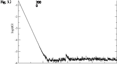
plate in terms of the small, dimensionless parameters. If thickness is added to the plate, how do these coefficients vary?

If this thin profile is allowed to rotate freely about an axis placed at the leading edge, find the equilibrium incidence. Hint: the moment of the aerodynamic forces is zero (neglect weight). Is the equilibrium statically stable?

3.9.7

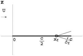
A thin flat plate has a hinge located at (xf, 0), 0 < Xf < c, about which the end of the plate can rotate by an angle Sf (positive down) and that plays the role of a flap. The equation of the thin plate is given by:

Подпись:0, 0 < x < Xf
Sf (xf — x), xf < x < c

Calculate the slope d’ (x) of the plate (check your algebra as other results depend on this). See Fig. 3.31. Let tf be the value of the parameter t corresponding to the flap hinge in the classical parametric representation of the thin plate as x f = x(tf) = 2(1 — cos tf), 0 < tf < n. Using the formula derived in class A0 = а — П jn d'[x(t)]dt, calculate A0. Check your result for tf = n (xf = c). Conclude. Check your result for tf = 0 (xf = 0). Conclude.

What is the angle of adaptation aadapt(tf, Sf)? Check your result for tf = n (xf = c). Conclude. Check your result for tf = 0 (xf = 0). Conclude. Calculate the incidence of adaptation for xf = 3c/4 and Sf = 10°.

Sketch the plate and, qualitatively, the flow at the calculated incidence of adaptation, in particular the streamlines near the leading edge and the trailing edge.

Calculate A1 in terms of the average camber d, tf and Sf. Check your result for tf = n (xf = c). Conclude. Give the value of the aerodynamic coefficients C; and Cd in terms of a, tf and S f. If thickness is added to the thin plate, how will these coefficients be affected?

References

1. Glauert, H.: The Elements of Aerofoil and Airscrew Theory, 2nd edn. Cambridge University Press, Cambridge (1948)

2. Chattot, J.-J.: Optimization in applied aerodynamics. Comput. Fluid Dyn. J. 9(3), 306-311 (2000)

3. Drela, M.: MSES—Multi-element airfoil design/analysis software. http://raphael. mit. edu/ research. html (1994)

4. Chattot, J.-J.: Computational Aerodynamics and Fluid Dynamics: An Introduction. Scientific Computation. Springer, Berlin (2004)

Summary of Chapter 3

In this chapter, small disturbance theory associated with thin airfoils is used to simplify and obtain linearized formulations of the tangency condition and pressure field. The general problem of inviscid, incompressible potential flow past thin airfoils is now fully linear and can be decomposed into symmetric and lifting problems that are handled by a distribution of sources/sinks for the former, and of vortices for the latter.

The symmetric problem does not contribute to lift or moment, however, thick­ness affects the pressure distribution. The lifting problem leads to the fundamental integral equation of thin airfoil theory, which relates the vorticity distribution Г’ to the induced velocity component w along the profile, via the tangency condition. The solution of the fundamental integral equation is worked out using a singular term plus a Fourier series of regular terms for the vorticity along the cut [0, c]. It is shown how the singular term and the Fourier coefficients can be obtained for a given thin cambered plate at incidence. The interpretation of the singular term coefficient as A0 = a — o. adapt points to the existence, for each thin airfoil of an angle of adapta­tion, that depends purely on the airfoil geometry, such that the leading edge satisfies also a Kutta-Joukowski condition. This has a practical interest since separation at a sharp leading edge is likely to occur in real fluid when a = aadapt. The positive role of thick leading edge is also emphasized in this regard.

The forces and moments are obtained for arbitrary airfoils and from these, the center of pressure can be found. In all cases, the drag is zero (d’Alembert paradox). In general, as the incidence varies from large negative to large positive values, the center of pressure will travel from —^ to +ro. At very high or low incidences, the center of pressure moves to the quarter chord, pp = 1. The aerodynamic center for all thin airfoils is found to be at the quarter chord, p – = 4.

Application of the theory to the design of a thin airfoil exemplifies the practical aspects and usefulness of the results derived in this chapter. It is also shown that some particular thickness and camber distributions can be related to the concept of minimum pressure gradient field surrounding the airfoil. This idea has been applied to the design of double element airfoils, which have proved to perform well in practice.

Finally, numerical aspects of the solution of the fundamental integral equation of thin airfoil theory are given, which, properly implemented, contribute to fast and accurate analysis tools for the designer.

Numerical Solution of the Fundamental Integral Equation

Numerical solution of the fundamental integral equation can be obtained cheaply and accurately for arbitrary geometries. Such simulation tools replace advantageously the analytical method and allow to spend more time analyzing the results and understand­ing the physics, than computing integrals. The benefit of the theory is undeniable in demonstrating the dependency of lift and moment on solely a few modes and in helping understand the suction force and the notion of ideal angle of attack. The fundamental integral equation of thin airfoil theory

w(x, 0) = — —Цd£ = U(d'(x) – a (3.117)

2W0 x – £

is solved using finite differences. One important feature in the discretization of the problem is the use of the Glauert transformation, which allows for rapid convergence and high accuracy. Let the distribution of control points be given by

This very large, practically full matrix, can be solved efficiently by relaxation as

ІХ

Подпись: n, n+1ai, i АГ = U (f’ – a) – £ ai, j Гп, п+1, i = 2, 3,…,ix – 1 (3.124)

j =2

Numerical Solution of the Fundamental Integral Equation(3.125)

and Г”+1 = Г" +шАГі. n represent the iteration index and the upper index (n, n +1) indicates that the value may be “old” or “new”. The relaxation factor [4], 0 < w < 2, can be chosen as high as w = 1.8.

The convergence history with a fine mesh of ix = 101 points is shown in Fig. 3.27. It takes about 500 iterations to converge to machine accuracy.

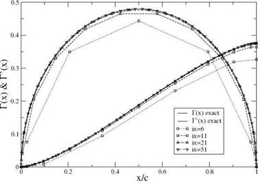
Results for the parabolic plate at zero incidence are presented in Fig.3.28 and compared with the analytic solution for mesh systems of ix = 6, 11, 21 and 51 points. As can be seen, results are sufficiently accurate with ix > 21.

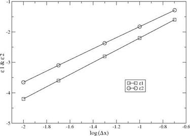
The convergence with mesh refinement is shown in Fig. 3.29, where the following error norms have been used

Numerical Solution of the Fundamental Integral Equation

Numerical Solution of the Fundamental Integral Equation

(3.126)

Numerical Solution of the Fundamental Integral Equation

Fig. 3.28 Comparison with analytic solution of Г and Г’

Numerical Solution of the Fundamental Integral Equation

Fig. 3.29 Rate of convergence of Г and Г

Подпись: ix-1
Numerical Solution of the Fundamental Integral Equation
Подпись: (3.127)

The circulation Г converges with a slope of 2. The rate of convergence of 1.8 for Г’ is slightly less, probably due to the singularity in slope at x = 0 and x = c.

A Family of Profiles with Minimum Pressure Gradient

The Society of Automotive Engineering (SAE) organizes every year a collegiate design competition which encourages the students to design, build and fly a remote controlled model airplane, capable of carrying a maximum payload, and that can take­off within 200 ft from a start line, make four-900 turns, touch down and roll within 400 ft from a prescribed line. Besides these take-off and landing constraints, other requirements are imposed such as not losing parts at any time during the run, using an unmodified specified gas engine with provided fuel, as well as some geometric constraints that vary from year to year (imposed maximum span or maximum surface area of the lifting elements, etc.)

From these rules, it is clear that one would like to use a wing profile having high lift capabilities Cimax. Indeed, assuming that the best propeller has been chosen for the engine during the acceleration phase on the ground, the velocity is primarily governed by the total airplane weight. In order for the airplane to rotate and take-off with a maximum payload, a high lift coefficient is needed.

From the thin airfoil theory and inviscid flow view point, all airfoils are equivalent in the sense of being capable of giving a Ci value

A Family of Profiles with Minimum Pressure Gradient(3.94)

by a combination of interchangeable incidence and camber. Of course, in reality, viscous effects at a given Reynolds number, will limit the maximum lift coefficient to a value that depends on the airfoil camber and thickness distributions. The problem of optimization seems therefore irrelevant, unless one accounts for viscous effects. One idea is to try to minimize the negative impact of viscosity by searching for the profile that will create the “least disturbance” to an inviscid flow.

A Family of Profiles with Minimum Pressure Gradient Подпись: (3.95)

Potential flows have been shown to minimize the integral of pressure over the domain surrounding the profile (Bateman principle), i. e. to minimize

where Q represents the domain of the flow.

Here we propose to minimize the integral of the pressure gradient

Подпись: I =A Family of Profiles with Minimum Pressure Gradient(3.96)

with the understanding, as will be seen in a later chapter, that very large negative pressure gradients increase shear stress and friction drag, whereas very large positive pressure gradients trigger boundary-layer separation and pressure drag. Using the small perturbation assumption p(x, z) = рж — pUu, the integral can be written as

A Family of Profiles with Minimum Pressure Gradient(3.97)

The square of the first derivatives can be replaced by the equivalent expression, say for the x-derivative

Подпись:/du 2 d ( du d2u

dx dx dx U dx2

A Family of Profiles with Minimum Pressure Gradient Подпись: (3.99)
A Family of Profiles with Minimum Pressure Gradient

and similarly for the z-derivative, so that the integral becomes

The last term vanishes because u, like w, ф and ф are solution of Laplace equation. The divergence theorem is applied to the first term and results in a contour integral that vanishes at infinity, but contributes on the profile contour to the term

A Family of Profiles with Minimum Pressure Gradient(3.100)

дії is the profile boundary. dl = (dx, dz) represents an element tangent to the profile surface in the clockwise contour integral and the normal element ndl = (dz, —dx) points into the profile. Making use of the two governing PDEs, the integral can be written as

Подпись: dw dw 1 —, — -ndl = —U2 A Family of Profiles with Minimum Pressure GradientПодпись: (3.101)dw

u dx

on dx

Now, we can use the following expressions for u and w on the upper and lower surfaces

Подпись: (3.108), Г'(х) Г'(х)

u+(x) = ue(x) + 2 , u (x) = ue(x) – 2 (3.102)

і e'(x) e'(x)

w+(x) = wd(x) + U, w (x) = wd(x) – U (3.103)

dx — [1]e + Id

A Family of Profiles with Minimum Pressure Gradient Подпись: dx Подпись: (3.104)

where ue (x) represents the horizontal component of velocity induced by the distrib­ution of sources and sinks (thickness problem) and wd (x) is the vertical component induced by the vorticity distribution (lifting problem). Replacing the contour integral by a simple integral from zero to c, substituting the above expressions and after some simplification, one gets

This result indicates that the minimization problem can also be decomposed into symmetric (Ie) and lifting (Id) problems.

A Family of Profiles with Minimum Pressure Gradient Подпись: 1 U2 Подпись: Uuee"dx, ue (x) 0 Подпись: U fc e'(Q 2n 0 x — £ Подпись: (3.105)

The symmetric problem reads

We will proceed as was done for the lifting problem. Let

e'[x(t)] = 2{£01^ +£1 En sinnt] 0 < t < n x (t) = 2 (1 — cos t) ’

Подпись: e'[x(t)] Подпись: 4 E0 sin t Подпись: (3.107)
A Family of Profiles with Minimum Pressure Gradient

Note that we have kept a singular term which tends to infinity as t ^ 0 (i. e. x ^ 0). The behavior near the leading edge is

which corresponds to a parabolic blunt nose. The trailing edge is cusped. The hori­zontal velocity component is

which is the Quasi-Joukowski thickness distribution, with E0

e'[x (t )] = 2E0 – 2sint

sin t

Upon integration, the thickness distribution is obtained

e[x(t)] = E0c sin t (1 + cos t) = 4E0c^^ ^1 – ^ 2

Подпись: 4 e 3+3 c .

A Family of Profiles with Minimum Pressure Gradient

Adding an extra term, mode 2, with E2 = — | E0 produces a profile with a far – forward maximum thickness

which is the third thickness distribution introduced earlier, with E0 = f.

With the lifting problem, we will assume that the leading edge is adapted, since we remarked that a singular leading edge will not behave well in presence of viscous effects and will probably trigger separation, Chattot [2]. Proceeding as was done earlier in the chapter, we let

O

Гr[x(t)] = 2^ 22 An sin nt (3.114)

n=1

using only regular terms in the series, which means that the flat plate is not an element of this family. Hence we have

to

wd (x) = U^^An cos nt (3.115)

n=1

After some algebra one gets in this case

TO

Id = nAl (3.116)

n=1

Keeping, for example, only the first mode results in the parabolic cambered plate at zero incidence, Fig. 3.17.

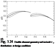
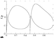
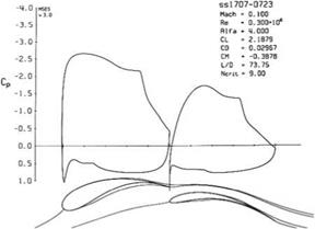
More interesting results have been obtained with this approach in the design of multiple element airfoil camberlines. For instance, a double element airfoil can be designed for minimum pressure gradient and a given high lift coefficient, say Ci = 2.3. A number of design parameters have to be chosen: the relative length of each element, the gap width between the two elements. Here we used a 50-50 chord percentage for each element as overlap was not advantageous with the SAE rules. The inviscid result indicates that the first element has Cl1 = 1.145 and the second element C12 = 1.155. See Fig. 3.24 for the profile geometry where 12% thickness distributions have been added to the camberline design. The inviscid Cp distributions are also shown. The gap width was set by analyzing several designs with a viscous code, MSES for multiple element airfoils by Drela [3] and selecting the best result. The final design geometry and Cp distributions are shown in Fig. 3.25. Note that the second element thickness was reduced to 7 % as it was found that the stagnation point was not moving with incidence, whereas the thickness of the first element was increased to 17 % to allow for large displacements of the leading element stagnation point. The maximum lift coefficient was found to be Cl = 3.1, (see Fig. 11.6).

Подпись: x/c Fig. 3.24 Double element geometry and inviscid C p distributions at design conditions Подпись: x/c

A wind tunnel model of a low aspect ratio half-wing has been built with foam core and carbon fiber skin which validated the high lift capabilities of the design by comparison with the numerical model, Fig. 3.26.

Подпись: Fig. 3.25 Double element geometry and viscous Cp distribution at design conditions
A Family of Profiles with Minimum Pressure Gradient

Fig. 3.26 Double element wind tunnel test model

Example of Design Problem

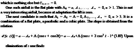
Design the simplest airfoil (thin cambered plate) such that the center of pressure stays at the quarter-chord at all incidences (small a’s) and the design lift (Cl)des > 0 is obtained at the angle of adaptation aadapt. By simplest airfoil, we mean one that has the smallest number of non zero Fourier coefficients. This has a practical interest for a “flying wing” configuration, where the long fuselage providing a moment from the tail is not available to balance the pitching moment at different incidences.

Example of Design Problem

The condition reads


Xc. p. A0 + A1 — “2r 1

C 4 (A0 + 4


(3.87)


Upon multiplying by the denominator (not zero, since C; = 0), one finds


A2 = A1


(3.88)


Example of Design Problem

x x 2

d (x) = a — A0 + A 2 — 10 + 8 2


(3.90)


Integrating from 0 to x gives


Example of Design Problem

(3.91)


The condition that d (c) = 0 determines A0 = a — A. Substitution of this result in the expression of the lift coefficient results in Ci = 2n (a + – A). Finally, the equation of the camberline can be factorized as

d(x) = Ax (7 — 80 (l — 0 (3.92)

From the previous result, the ideal angle of attack is aadapt = A and the associated lift (Ci)adapt = nA = (Ci)des. This determines the unknown coefficient A:


A (Cl)des

n


(3.93)


A sketch of the thin cambered plate at incidence of adaptation is shown in Fig. 3.23.


Fig. 3.23 Thin cambered plate at design conditions


z


L’


U


x


c_

4


a


c


0


Example of Design Problem

Example of Design Problem