In the following, the streamfunction will be chosen as an intermediate function to solve for the flow velocity field. Similar results would be obtained with the velocity potential.
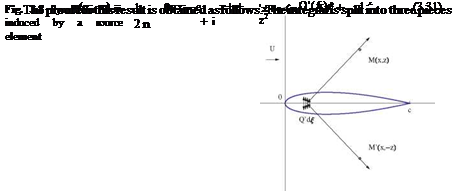
We consider a small element along the x-axis of length d£ with a distribution of source/sink dQ = Q'(£)d£. The contribution of this element to the perturbation streamfunction at a point M (x, z) is given in Cartesian coordinates by

 , , Q(£)d£ t
d ф = arctan l
2n x – £,
The perturbation velocity components are obtained by taking derivatives with respect to x and z. Note that the derivatives will be carried out under the integral sign, which requires some regularity of the integrand and convergence of the integral. We shall assume that these conditions are fulfilled.
Note that u is even and w is odd in z. This is consistent with the symmetry of the flow about the x-axis. For that reason, u will be continuous across the cut [0, c], whereas w will be allowed to jump. Let < a >= a+ – a~ represent the jump of a across the cut, then < u >= 0 and < w >= 0. Since the pressure is related to u, the pressure will be continuous across the cut, and w will have a jump corresponding to the change of sign of the profile slope (± ) between the upper and lower surfaces.
See Fig. 3.8.
The tangency condition on the upper surface is applied by letting z ^ 0+ while
0 < x < c and
w(x, 0+) = Uf’+(x) = 1 Ue'(x) (3.29)
which will also, by symmetry, enforce the tangency condition on the lower surface. In the process, the integral goes to zero, almost everywhere, except at £ = x, where the integrand is of the form 0. One can show that the limit is finite and equal to
lim w(x, z) = Q'(x)

z^0+ 2
where e > 0 is a small number. The first and last integrands are regular and
z2 2 ^ 0 as z ^ 0, in other words
(x — £)2+z2
In the middle integral, the dummy variable £ is replaced by t s. t. £ = x + zt. The integral becomes

 We(x, z)
Now, if Q ’ is a smooth function, it can be expanded in Taylor series as Q (x+zt) = Q(x) + ztQ"(x) + O(e2). Note that — e < zt < e. Substitution of this last result into the integral yields
Q ‘(x) z dt Q'(x) –
We(x, z) = 2 + O(e) = [arctan t] 1 e + O(e) (3.34)
2n e 1 +12 2n z
z
Letting z ^ 0+, followed by e ^ 0, gives the anticipated result.
By identification with the previous equation, the source/sink strength is found to be Q'(x) = Ue'(x). When the thickness increases, sources are used and when it decreases, sinks are used. For a closed profile the net sum of sources and sinks is zero, a consequence of e(0) = e(c) = 0.
Fig. 3.9 Limiting process e ‘ (x)
for principal value integral x – f
Now that the singularity distribution is known, the perturbation velocity field can be calculated using the above equations for u(x, z) and w(x, z). We are especially interested by the velocity on the obstacle. We know w already and u is given by
U Ґ e’ (i)
u(x, 0) = di (3.35)
2n J0 x – І
Note that the integrand is singular at І = x. The singularity is a “simple pole”. A finite value can be obtained according to the limiting process

 Г-e e'(£) c e'(0 ^
——d e + – – d Є
0 x e x+e x e
In this process, the two diverging contributions cancel out because the areas, as depicted in Fig.3.9, are equal and opposite. Such integrals are called “principal value” integrals.
The proof is easily obtained by studying the following limit for the remainder

 x – e e£) *+e e’(£)
r = lim d e +
e^° x-e x – e x+e2 x – І
and making use of e2 ^ e and of the Taylor expansion
(i x )2
e£) = £(x) + (І – x)e"(x) + 2 e"x) + O(e3) (3.38)
where e has been written as e = x + (e – x).
The first term in R integrates as
 X — Є2 P (£)
—-d£ = e'(x) ln є — ln є2 — e"(x) є — є2 + O(є3)
which vanishes in the limit є ^ 0.
Consider as example, the flow past the symmetric wedge of semi-angle в at zero incidence. The thickness distribution is e(x) = 2вх for small values of в. This results in Q'(x) = 2Uв = const. The velocity along the wedge is


 , n, Uв rc d£ u(x, 0) =
n 0 x — £
Going through the limiting process in detail, let
 Uв ( Г—є d£ + fc d£
= (ln x — ln є + ln є — ln(c — x))
Note that the terms in ln є cancel out and the limit for є ^ 0 is simply
U в x
и (x, 0) = — ln———-
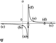
The pressure coefficient, Cp = — 2u (x, 0)/U is shown in Fig.3.10. Note that the areas under the curve are equal and of opposite signs. For this reason, the resulting pressure force in the x-direction (drag) is zero.
To close this section, it is worth mentioning that, although thickness does not contribute to forces and moments, it will be beneficial in mitigating adverse viscous effects due to sharp leading edges.
Fig. 3.10 Pressure coefficient along the wedge


![]()
![]() (d)
(d)


 Application:
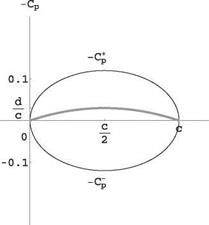
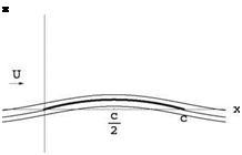 Fig. 3.17 Streamlines of the flow past a parabolic plate at zero incidence


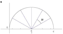


 etc.. .If the profile camber is not a polynomial, or is defined by piecewise continuous functions, the Fourier coefficients have to be calculated using the general method of integration, using orthogonality of the modes as


 Uв ( Г—є d£ + fc d£