Category Theoretical and Applied Aerodynamics

Supersonic Linearized Theory (Mo > 1)

The wave drag coefficient (Cd)a=0 is given by

dx 16 ґв[8]

c 3в Vc/

(Cd )a=0 = (f’+(X )f + (f ‘-(X ))"

as seen in class.

Hence the lift and wave drag coefficients are:

4a

Cl (a) = — = 0.0403

P

16 /e2 4a2

Cd(a) = 3в U + IT = a0315

3в c) в

The lift and wave drag upper bounds for the fin are

12

L = 2 pV[9] 2bc Cl = 106 N

D = 2pV2bc Cd = 82.9 N

15.3.1 Lifting Line Theory (3-D Inviscid Flow)

15.3.2.1 Induced Drag in Cruise The induced drag Di in (N) is given by

1 2 c2l

Di = – pV 2 5—– —

i Г neAR

1 1 pV2neb2

Подпись: Elimination of CL yields: Подпись: Di Подпись: W2

The equilibrium equation along the vertical axis during horizontal cruise in dimen­sional form (neglecting the lift of the tail) reads:
Supersonic Linearized Theory (Mo > 1)
Подпись: 2

The drag penalty is = 0.21, i. e. a 21 % increase in induced drag.

Thin Airfoil Theory (2-D Inviscid Flow)

15.3.1.1 Incompressible Flow (M0 = 0)

As seen in class, the coefficients for a parabolic camberline are

Thin Airfoil Theory (2-D Inviscid Flow)

A2 = ••• = An = 0, n > 2

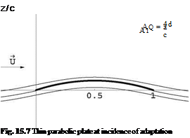
The angle of adaptation or ideal angle of attack is a = 0 since A0 = a. The flow satisfies two Kutta-Joukowski conditions. The leading edge flow has finite velocities. See Fig. 15.7.

The lift coefficient is given by Cl = 2n(A0 + A1/2) = 2n(a + 2d). The incidence of zero lift is thus a0 = -2 = -0.172 rd = -9.85°.

The moment Cm, ac is given by Cm, ac = Cm, o + X~Ci = Cm, o in this case. Indeed: Cm, o = —§ (A0 + A1 – A2/2) = —П – which is the value of Cm, ac for this profile.

The upper limit of the weight (in N) that a wing of chord c = 0.368 m and span b = 4.877 m could lift at Cl = 2 corresponds to the 2-D solution. The lift per unit span is given by

12

L’ = 2pV2c Ci

hence the total lift would be

L = pV2bc Cl = 242.4 N

The corresponding mass at take-off would be M = 24.7 kg.

Airplane Longitudinal Equilibrium

15.2.3.1 Global Coefficients

Aerobrick 2003 has the following lift and moment coefficients in terms of the geo­metric angle of attack a (rd) and tail setting angle tt (rd):

CL(a, tt) = 3.88a + 0.5 + 0.481tt
CM, o(a, tt) = -1.31a – 0.124 – 0.452tt

dCM, o

The aerodynamic center is given by ^ Щ = 0.338.

re ~da ‘

To satisfy the 4 % static margin, the center of gravity must be located in front of the aerodynamic center with

Tcg = ^ – 0,04 = 0,298

lref lref

Definition: the aerodynamic center is the point about which the moment is inde­pendent of the incidence angle.

It is clear from the above calculation of that CM o (a) + racCL (a) is indepen-

lref ’ lref

dent of a and reads

Cm, ac(tt) = 0.045 – 0.289ft

15.2.3.2 Take-Off Conditions

The moment at the center of gravity is given by

Cm, cg(a, tt) = См, о(а, tt) + Cl (a, tt) = —0.154a + 0.025 — 0.309tt

lref

At equilibrium the moment is zero, hence, solving for the equilibrium incidence:

aeq (tt) — 0.162 2.0tt

The equilibrium lift is then

CLeq(tt) = 1.129 — 7.28tt

At take-off, the airplane lift coefficient is CL = 1.44 = 1.129 — 7.28(tt)t—o, which can be solved to give

(tt )t—o = -0.0427 = -2.45°

At take-off the angle of attack will be

(aeq)t—o = 0.2474 = 14.17°

15.3 Solution to Problem 3

Lifting Line Theory (3-D Inviscid Flow)

15.2.2.1 Flow Model

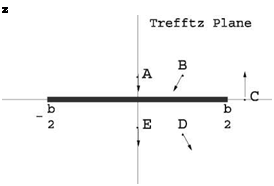
The vortex sheet is a stream surface, wetted on both sides by the fluid, hence the tangency condition imposes that the ш-component of the perturbation be continuous. Across the vortex sheet the pressure is continuous, hence the u-component of the perturbation is continuous (Cp = —2u/U).

Velocity vectors near the vortex sheet: see Fig. 15.4.

Fig. 15.4 Induced velocities near the vortex sheet

15.2.2.2 Подпись: z Improved Lift of a Rectangular Wing

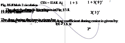
The combination of modes 1 and 3 is represented in Fig. 15.5.

The total lift of a wing is given solely in terms of A1 and can be written as CL = n AR A1. The maximum circulation is obtained for t = | and is rmax = 16 UbA1. Hence A1 = 1тиъ and the corresponding lift is Cl = n AR jU = 8 (cl )eUiptic, a

12.5 % increase for the high lift rectangular wing.

Подпись: sin 3t sin t

Lifting Line Theory (3-D Inviscid Flow) Lifting Line Theory (3-D Inviscid Flow)
Подпись: UA1(1 + 2 cos21)

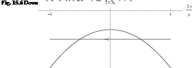
As seen in class, the downwash for the high lift wing is given by

The distribution of downwash is parabolic and is compared with that of the elliptic wing WT[y(t^elliptic = –Ir. See Fig. 15.6.

15.2.2.3 Drag Penalty

The induced drag of the wing is given by

Подпись: 28Подпись: 27 (CDi)ellipticLifting Line Theory (3-D Inviscid Flow)

Lifting Line Theory (3-D Inviscid Flow)

CDi = nAR a2^1 + ‘"+nAl + ••• ^ = nAR a2 The drag penalty is a 3.7 % increase in induced drag.
. Thin Airfoil Theory (2-D Inviscid Flow)

As seen in class

Ci — 2n(a + 2, Cm, o — _2 (“ + 4

For a given value of camber and Cl, the lift coefficient relation can be solved for the angle of incidence as

Ci d

(a)Ci —0.5 — – – 2- — —0.0924rd — -5.3° 2n c

Ci d

(a) Ci —2.0 — – — 2 — 0.1463 rd — 8.4°

2n c

The corresponding moments are

(Cm, o)Ci —0.5 — -0.395 (Cm, o )Cl —2.0 — -0.77

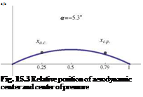
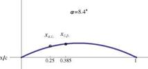
The center of pressure is found from Xf — , that is

(—)q —0.5 — 0.79

ci

(—)Cl —2.0 — 0.385

ci

See Fig. 15.3.

15.2.1.2

Подпись: z/c z/c Fig. 15.3 Relative position of aerodynamic center and center of pressure
. Thin Airfoil Theory (2-D Inviscid Flow)

Supersonic Linearized Flow (Mo > 1)

The lift coefficient Ci in supersonic flow is given by

Ci (a) = 4 a, where в = ^M — 1.

Подпись: Cm,o (a) . Thin Airfoil Theory (2-D Inviscid Flow)

The moment coefficient is

where (Cm, o)a=0 = | q(f’+(X) + f’ (X))cit.

. Thin Airfoil Theory (2-D Inviscid Flow) Подпись: 16 d в c . Thin Airfoil Theory (2-D Inviscid Flow) Подпись: 8 d 3в c

The thickness distribution has no effect on the moment which reduces to the camber contribution

The moment reads Cm, o(a) = — d. — 2a. The center of pressure is given by

xcp 1 e(Cm, o)a=0 1 + 2 d 1

c 2 4a 2 3 c a

Equilibrium of the Glider (3-D Incompressible Flow)

15.1.3.1 Glider Effective Aspect Ratio

As a glider (engine off), the glider has the following lift and moment coefficients in terms of the geometric angle of attack a (rd) and tail setting angle tt (rd):

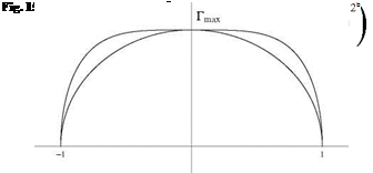
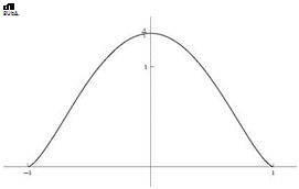
Подпись: r(0 2UbA, Fig. 15.2 Distribution of circulation

Cl (a, tt) — 5.3a + 1.56 + 0.5tt
Cm, o (a, tt) — —1.7a — 0.43 — 0.45tt

The effective aspect ratio AR of the glider (wing+tail), assuming ideal loading is given by the lift slope

Подпись: dCL d a Подпись: 2n 1 + -21 + AR

Подпись: Solving for AR gives Equilibrium of the Glider (3-D Incompressible Flow) Подпись: 10.8.

— 5.3

15.1.3.2 Equilibrium Angle of Attack

The equilibrium of the moment corresponds to

xcg

CM, o(aeq, tt) + 7—- CL (aeq, tt) — 0

lref

Equilibrium of the Glider (3-D Incompressible Flow)

When the lift and moment coefficients functions are replaced in the above equa­tion, taking into account ^ — 0.29, the solution for aeq(tt) reads

Plugging this result in the lift coefficient gives

Cl (tt) — 5.3(0.137 — 1.87tt) + 1.56 + 0.5tt — 2.286 — 9.411tt

which for CL — 1.9 results in tt — 0.041 rd — 2.35°.

The corresponding angle of attack is aeq — 0.06 rd — 3.46°.

15.1.3.3 Landing Speed

Подпись: ueq — Подпись: 2mg pAref (CL ) max Подпись: 13.8 m/s

At sea level, p — 1.2kg/m3, g — 9.81 ms—2, given that the total mass m — 15kg, the maximum lift coefficient (CL)max — 1.9 corresponding to the reference area Aref — 0.68 m2, the landing speed corresponds to the equilibrium equation for the force in the direction normal to the trajectory. i. e.

15.2 Solution to Problem 2

Lifting Line Theory

15.1.2.1 Flow Model

The vortex sheet that is shed by the finite wing is composed of vortex filaments parallel to the x-axis, that induce two velocity components, v and w in its proximity, that vanish at infinity upstream, but not at infinity downstream (Trefftz plane). The kinetic energy of the flow increases along a stream tube. An energy balance indicates that work must be done, for the kinetic energy to increase. This work corresponds to the work of the thrust that is needed to balance the induced drag, in order to maintain the motion. The vortex sheets is a trace of the passage of the wing, that does not disappear in inviscid flow.

The lift and induced drag coefficients are given by

Cl = n ARAi

Cdi = nAR (A2 + 2A2 + •••+ nA’2 + •••)

15.1.2.2 Non Singular Lift Distribution

The combination of modes 1 and 3 reads

Подпись: Г [y (t)]= 2Ub (A1 sin t + A3 sin 3t) y (t) = — cos t

Taking the derivative with respect to y gives

dГ dГ dt d A1cost + 3A3cos3t

dy dt dy it sin t

A necessary condition is that the numerator go to zero when t ^ 0. This will be satisfied if A3 = – A1. It is possible to verify that, with this condition, the derivative will go to zero, dry & 16UA1t, as t ^ 0.

See Fig. 15.2.

15.1.2.3 Drag Penalty

Lifting Line Theory Подпись: 4 LL 3 nAR

For a given CL (at take-off), the coefficient A1 is fixed since A1 = Ar. The induced drag of the wing is given by

The induced drag has been increased by 33 %, which is not negligible. The efficiency factor e = (1 + £)-1 = 4 = 0.75.

Equilibrium About an Axis

Equilibrium About an Axis

The aerodynamic moment coefficient Cm, o is defined as

If the profile is attached to a vertical axis located at x — 0 (nose of profile), the equation of equilibrium that will give the equilibrium angle of attack aeq is given by the equation of the moment coefficient

n d

Cm, o (aeq) = 0 —— 2 aeq + 4^

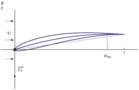
Fig. 15.1 Equilibrium position for the profile

Подпись: z c aeq is found to be

d

aeq = —4 = —0.08

c

See Fig. 15.1.

The equilibrium is stable because ‘ЩОг < 0.

Solutions to Problems

15.1 Solution to Problem 1

15.1.1 Thin Airfoil Theory (2-D Inviscid Flow)

15.1.1.1 Quiz

In subsonic flow, the aerodynamic coefficient dependency upon the small parameters is given in Table 15.1. In supersonic flow, the aerodynamic coefficient dependency upon the small parameters is given in Table 15.2.

15.1.1.2 Lift Coefficient

The lift coefficient Ci in incompressible flow (low speed) is given by

Solutions to Problems

6.28(0.0873 + .04) — 0.8


At M0 — 0.7, using Prandtl-Glauert correction one finds

Solutions to Problems

15.1.1.3 Drag Coefficient

If the drag coefficient of the same profile at a — 0 and M0 — 1.4 is (Cd)M0—1.4 — 0.02, the drag at M0 — 2. is given by © Springer Science+Business Media Dordrecht 2015

J. J. Chattot and M. M. Hafez, Theoretical and Applied Aerodynamics,

DOI 10.1007/978-94-017-9825-9_15

Aerodynamic coefficient

e/c

d/c

a

Ci

n

y

y

Cm, o

n

y

y

C

m, ac

n

y

n

Cd

n

n

n

Table 15.1 Subsonic flow

Подпись: 0.02 = 0.0113
Solutions to Problems
Подпись: 0.9798 1.732
Подпись: (Cd )M0=2

Aerodynamic coefficient

e/c

d/c

a

Ci

n

n

y

Cm, o

n

y

y

Cm, ac

n

y

n

Cd

y

y

y

Table 15.2 Supersonic flow

Подпись: Cd (a) Solutions to Problems Подпись: 0.289

At M0 = 2. if a — 5° then

The drag coefficient at M0 = 0.7 is

(Cd )M0=0.7 = 0

since this is a 2-D, inviscid, subsonic flow.

Equilibrium of the Glider

The AMAT12 has a rectangular main wing with span bm = 2.1m and constant chord cxm = 0.3 m. The tail is also rectangular with span bt = 1.0 m and chord cxt = 0.338 m. The equilibrium code provides the aircraft aerodynamic characteristics and a maximum take-off mass M = 18 kg. The reference area is Aref = Am + At. The reference length is lref = 2.12 m. The engine is turned off. The global aerodynamic lift and nose pitching moment coefficients are found to be

CL(a, tt) = 3.853a + 0.902tt + 0.716
См, о(а, tt) = -1.336a – 0.894tt – 0.06

where a represents the geometric incidence and tt the tail setting angle in rd.

14.10.3.1 Equilibrium About the Center of Gravity

Calculate the pitching moment about the center of gravity CM, c.g. (a), given that the center of gravity is located at xc. g./lref = 0.2868. (Hint: use the change of moment formula). Verify your result as the rest depends on it.

Is the airplane statically stable?

If the aerodynamic center of the glider is at xa. c. = 0.735 m, give the static margin SM in %.

14.10.3.2 Equilibrium Incidence

Write the equilibrium condition and solve the equation for aeq (tt). Check your algebra by substituting back into the equation.

14.10.3.3 Trimming for Maximum Distance

The equilibrium code calculates the tail setting angle for maximum CL/CD = 9.3 to be tt = 12°.

Find the corresponding values of CL and CD, as well as the descent angle в – Calculate the lift forces (in N) on the main wing and the tail, given that the velocity is U = 17.3m/s and the air density p = 1.1214kg/m3. The wing and tail lift curves are given respectively by

CLm(a) = 4.664a + 1.312
CLt(a, tt) = 2.342a + 2.583tt – 0.396