Category UNSTEADY AERODYNAMICS, AEROACOUSTICS AND AEROELASTICITY OF TURBOMACHINES

Example Problems

A finite element cyclic symmetry analysis was performed on a LPT turbine rotor (Blade BT). For the first 20 nodal diameter mode the reduced frequency is 0.23 and the mode shapes for the forward traveling wave are

[ —0.260 j [ —0.072 j

{a20c} = < —0.036and {a20s} = < —0.059 [ —0.638 J [ 0.149 J

Since 92.1% of the kinetic energy is in cosine mode, this mode is expected to dominate. The cosine mode has a pitching axis at (£=-0.056, n=0.407). For this location the traditional P-K method plot gives a critical reduced frequency of approximately 0.1. The sine mode has a pitching axis at (£=0.396, n=-0.482) for which the critical reduced frequency is approximately 0.5. Therefore, the traditional method judges the cosine mode to be stable and the sine mode to be unstable.

This case was run using the method described herein with using the blade described in Reference 1 for the baseline work matrices. The results are given in Table 1. As can be seen the total work is dominated by Wcc with a significant contribution from the interaction terms, WC5 and W5C. This interaction terms results in a stabilizing effect for the forward traveling wave and a destabilizing effect for the backward traveling wave. The work associated with the steady pressure has a relatively small effect on the total work. The critical damping ratio, £, is given for both the current method and a that of a full 3D, viscous, CFD method. Both modes are judged to be stable and there is relatively good agreement between methods.

The above analysis was performed for additional nodal diameters and the results are shown in Figure 4.

Table 1. Work and Damping for Blade ВТ, Mode 1, 20 Nodal Diameters

Work Component

Forward Traveling Wave

Backward Traveling Wave

wcc

-61.6

-40.2

w„

-0.3

0.3

wcs

14.5

10.4

wsc

5.7

4.1

Wps

-2.2

2.2

wcyc

-72.9

-31.4

c

0.89%

0.39%

c (CFD Method)

0.62%

0.27%

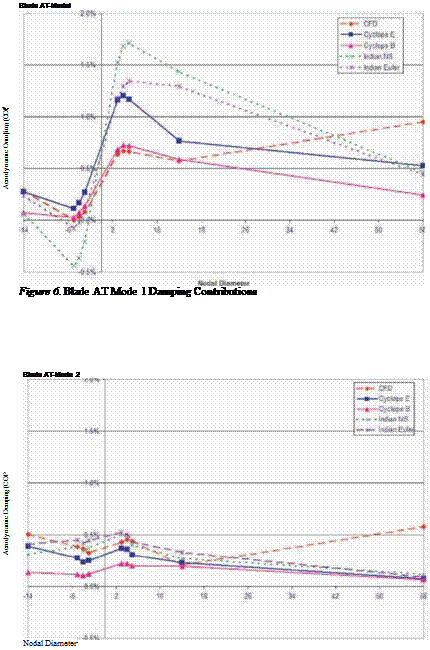
The results labeled Cyclops E were obtained using the current method with the baseline work matrices for the blade described in Reference 1 using a 2D inviscid code. Those labeled Cyclops В were obtained using work matrices obtained from a midspan section of blade ВТ, also using a 2D inviscid code. In addition results labeled Indian NS (Navier-Stokes) and Indian Euler are from a similar method developed at the University of Florence [Amone et al., 2003]. The Indian results were based on baseline aerodynamics for blade ВТ. Similar results for the second mode of blade ВТ are shown in Figure 5. For both modes the current method predicts the trends of damping versus nodal diameter reasonably well. With respect to using the current method as a preliminary design screening method, the overall stability is predicted correctly for these two modes (for both baseline work cases).

Blade AT was also analyzed with the new cyclic symmetry method and com­pared with CFD. These comparisons are shown in Figures 6 and 7.

Although not shown, similar comparisons have been made for three modes of two additional blades. For a total of 10 cases the overall stability agrees with the full 3D CFD method in all cases except one, where the current predicts

Example Problems

Figure 4. Aerodynamic Damping for Blade BT Mode 1


Blade BT • Mode 2


Подпись: Aerodynamic Damping (Critical Damping Ratio)

Example Problems

Example Problems

instability and the 3D CFD method predicting stability. This type of error is preferred for a preliminary design screening tool.

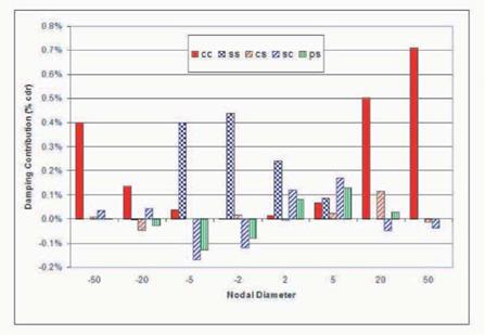
The results for Blade BT were further examined to determine the contri­butions to total damping from the individual work terms. Four representative nodal diameters were selected for study. The 2 nodal diameter mode is nearly a pure sine mode (99.2% of total energy). The 5 nodal diameter mode is predom­inately a sine mode (90.8% of total energy). The 20 nodal diameter mode is predominately a cosine mode (92.1% of total energy). The 50 nodal diameter mode is nearly a pure cosine mode (99.9% of total energy). Figure 5 shows the damping contributions (critical damping ratio) from the Wcc, Wss, Wcs, Wsc, and WPs work terms. That is, the individual work terms are divided by 4n times the total energy. A positive number represents a stabilizing contribution.

The 2 nodal diameter results show that contribution of the interaction terms can be significant for nearly pure real modes. That is, the Wsc contribution is approximately half of the contribution of the Wss. The 5 nodal diameter for­ward traveling wave results show that the interaction term can be the dominant contributor. The effect of the steady pressure terms is anti-symmetric about zero nodal diameters. At 5 nodal diameters the contribution of the steady pres­sure term is larger than that of Wcc and Wss. In this case the contribution of the steady pressure term decreases as the number of nodal diameters is increased.

Example Problems

Steady Pressure Term

Now consider the work due to the steady pressure for the same rigid body mode shapes. It can be shown that for the forward traveling wave.

Wps = —nf [Ps (a • ns – as • nc)] dA =

A

—n I (ashc, t — a, c hs,£) J Ps cos (On (A)) dA + (ac hs, n — as hc, rj) J Ps sin (On (A)) dA

AA

The term 0N is the local angle between the surface normal and the chord line. Therefore the first integration term is the steady lift and the second is the steady drag. In general the work associated with the steady pressure is nonzero for airfoils producing lift and drag, and having both translational and rotational motion.

3. Backward Traveling Waves

For backward traveling waves the interblade phase angle changes sign and the mode shape is

ф = ac + ias

The work associated with the unsteady pressure then becomes Wup (backward traveling waves) = Wcc + Wss + Wcs — Wsc

Thus, the sign of the interaction terms is negative of that for the forward trav­eling waves. Note that all of these individual work terms are different from those of the forward traveling waves because the interblade phase angle is also switched in sign. The work associated with the unsteady pressure, W Ps, is the negative of that shown above for the forward traveling wave.

Rigid Body Mode Shapes

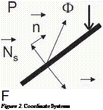
As in Panovsky and Kielb (1998) the three dimensional mode shapes are reduced to a two dimensional rigid body mode shape consisting of two trans­lations and one rotation about the leading edge (See Figure 2).

{

h^ic І Г

hvicand |ais| = < hvis

aic ais

The l subscript defines the nodal diameter, and determines the interblade phase angle, of the mode.

Rigid Body Mode Shapes

Now consider the term, Wcc.

Wcc — к J (etcPci) • ndA A

ec = h^c<p£ + hqc&q + асфа

ф^, фп are unit vectors in the £ and n directions, respectively фа is a vector in the n direction with an amplitude equal to the distance from the leading edge

Pci — h£cC£i + hqcCqi + ac Cai

The Ci terms are the imaginary parts of the linearized unsteady aerodynamic coefficients. As in Panovsky and Kielb (1998) the work term can then be writ­ten as

Wcc — { h£c hnc ac }

wii

W£n

w^a

( hic

wnS

wnn

wqa

hqc

_ Wai

wan

waa

[ ac

where

Wab = К f ((фаCbi^ • n) dA

By similarity

Подпись: Wss — { hs hns as } wa wiv w^a wnS wnn wqa _ wa£ waq waa The interaction terms can also be shown to be of the form his

hqs

as J

= { hc

ac }

wii

w^

w&

( his

Wcs

h

hnc

wv^

wnn

wqa

< hns

_ wJa^

waq

waa

as

wab =

фа Cbr

j • nj dA

The Cr terms are the real parts of the unsteady aerodynamic coefficients. To get the Wsc terms simply interchange the c and s subscripts. In the new method presented herein, these three-by-three work matrices must be generated for a baseline airfoil for a range of interblade phase angles and reduced frequencies. These matrices can then used for a wide range of LPT blade designs.

Work Associated with Unsteady Pressure

The unsteady pressure can be decomposed into contributions from the co­sine and sine components of the complex mode shape. For a forward traveling wave

Preal — pcr + Psi Pimag — pci psr

Wup — К J (etc (Pci – Psr) + as (Pcr + Psi)) • ndA

A

Wup — к f (etcPci) • ndA + к J (asPsi) • ndA — к f (etcPsr) • ndA + к J (asPcr) • ndA

A A A A

Wup (forward traveling wave) — Wcc + Wss — Wcs + Wsc

As can be seen Wcc and Wss (diagonal terms) represent the work due to the unsteady pressure acting on the mode shape producing that unsteady pressure. The Wcs and Wsc terms (off-diagonal) represent the interaction terms. That is, the work caused by the unsteady pressure due to the sine mode acting upon the mode shape due to the cosine mode, and vice versa.

Work for General Complex Mode Shapes

Work per cycle can be calculated by integrating the dot product of the local velocity vector with the local force vector over one cycle of vibration and the entire airfoil surface.

Подпись: F Figure 2. Coordinate Systems
Work for General Complex Mode Shapes

Airfoil Surface

4 = velocity N = normal vector P = surface pressure

For harmonic motion the displacement, normal vector and surface pressure can be written as (the bar over the variables indicates the complex conjugate)

Ф = І (фе~іиі + феіші)

N = Ns + і (пе~ш + Heiojt)

P = Ps + (pe~iujt + peiut)

Подпись: и г гтг Wcyc — 2 Подпись: ря Подпись: n Подпись: n) + Ns • (фр Подпись: dA

The work per cycle then becomes

Work for General Complex Mode Shapes Work for General Complex Mode Shapes Подпись: dA

For real mode shapes the work per cycle reduces to the familiar expression

Thus the steady pressure term does not contribute to the work when the mode shape is real. As will be shown, this is not the case when the mode shape is complex.

2. Work for Cyclic Symmetry Mode Shapes

For cyclic symmetry eigensolutions the mode shapes are complex. For a forward traveling wave

ф=(ас – ias) n = nc — ins

Where ac and as are commonly referred to as the cosine and sine modes. The work per cycle becomes

Подпись:Wcyc — 7Г J Ns * ificPimag H – &sPreal) Ps ific * ^s &s * ^c)

A L

Thus, the work has a component associated with the unsteady pressure and a component associated with the steady pressure.

WCyc — WUp + Wps

FLUTTER DESIGN OF LOW PRESSURE TURBINE BLADES WITH CYCLIC SYMMETRIC MODES

Robert Kielb

Duke University rkielb@duke. edu

John Barter

GE Aircraft Engines

Olga Chernysheva and Torsten Fransson

Swedish Royal Institute of Technology

Abstract This paper describes a new preliminary design method to conduct flitter

screening of LPT blades with cyclic symmetry mode shapes. As in the method for real mode shapes, baseline unsteady aerodynamic analyses must be per­formed for the 3 fundamental motions, two translations and a rotation. Unlike the current method work matrices must be saved for a range of reduced fre­quencies and interblade phase angles. These work matrices are used to generate the total work for the complex mode shape. Since it only requires knowledge of the reduced frequency and mode shape (complex), this new method is still very quick and easy to use. Theory and example applications are presented and compared with the results of full three-dimensional viscous CFD analyses. Rea­sonable agreement is found. The interaction effects of the cosine and sine modes and the work associated with the steady pressure are shown to generally be sig­nificant.

Подпись: Keywords:Flutter, Cyclic Symmetry, Preliminary Design, Low Pressure Turbines

41

K. C. Hall et al. (eds.),

Unsteady Aerodynamics, Aeroacoustics and Aeroelasticity of Turbomachines, 41-52. © 2006 Springer. Printed in the Netherlands.

1. Introduction

Panovsky and Kielb (1998) presented a method to conduct preliminary flit­ter design analysis for LPT blades. The study identified the blade mode shape as the most important contributor determining blade stability. Each mode shape is represented by three rigid body motions (two translations and one rotation) at the spanwise location of maximum displacement. These three motions can be described by a ‘pitching axis”. The critical value of reduced frequency is determined solely by this pitching axis location. By comparing this critical value with the actual reduced frequency, the stability is determined. Further in­vestigation using the same approach (Chernycheva et al, 2001) has shown that the overall stability behavior, as well as identification of the most stable and the most unstable regions as a function of blade mode shape remain remarkably similar for a rather wide range of physical and aerodynamic parameters of LPT blades with pure subsonic fbw. This method has been shown to be valuable in screening preliminary designs and identifying a minimal set of unsteady CFD analysis for final designs.

FLUTTER DESIGN OF LOW PRESSURE TURBINE BLADES WITH CYCLIC SYMMETRIC MODES

Figure 1. Local Blade Surface Velocity and Normal Vector

Many low pressure turbine (LPT) blade designs include a tip shroud (as shown in Fig. 1), that mechanically connects the blades together in a structure exhibiting cyclic symmetry. Since this arrangement is cyclically symmetric, each eigenvalue has a complex mode shape that can be represented by two real mode shapes that are commonly called the cosine and sine modes. The Panovsky-Kielb method results in two pitching axis locations for each eigen­value. Although this can easily be done, experience has shown that it is ultra­conservative. That is, virtually all designs are judged to be unstable. This is shown in Kielb et al. (2003). This paper also describes an approach to ex­tend the Panovsky-Kielb method to consider these complex mode shapes. As

in the Panovsky-Kielb method, baseline unsteady aerodynamic analyses must be performed for the 3 fundamental motions, two translations and a rotation. Unlike the current method work matrices must be saved for a range of reduced frequencies and interblade phase angles. These work matrices are used to gen­erate the total work for the complex mode shape. Since it only requires knowl­edge of the reduced frequency and mode shape (complex), this new method is still very quick and easy to use. This paper describes the complete theory for extension of the Panovsky-Kielb method, gives example results, discusses the importance of the interaction effects of the cosine and sine modes, and discusses the contribution to work associated with the steady pressure.

Results

The application of the method to two low pressure turbine rotor bladerows is presented; the two testcases are jointly defined with Duke University, and will be labeled AT and BT.

Complex flitter screening results, obtained through the present method, are compared with the results of a similar method based on CYCLOPS [Kielb and Barter, 2003]; for validation purposes, they are also compared with the aerodamping solution of TACOMA 3D Navier-Stokes time-linearized analysis [Holmes et al., 1997], performed on 3D fhxible modeshapes.

Since overall flitter stability behavior remain rather similar for similar ge­ometries and aerodynamic conditions of LPT blades with pure subsonic fbw [Tchernycheva et al., 2001], it is possible to perform the aeroelastic calcula­tions on a blade and then extend the results to another one, for preliminary design purposes.

In this paper, LARS calculations have been carried out on one section of the BT bladerow, and then used for both AT and BT complex flutter screening.

In figures 2a and 2b, the critical reduced frequency maps obtained on the BT selected section are presented.

Results

Figure 2a. BT bladerow: nearfield criti – Figure 2b. BT bladerow: farfield critical

cal reduced frequency map reduced frequency map

For each testcase, two complex mode families have been analyzed: the first will be referred to as ml, the second as m2.

In figure 3 a the aerodynamic damping coefficient is plotted versus the num­ber of nodal diameters for the AT ml mode family. The two INDIAN results are based on Navier-Stokes and Euler aeroelastic calculations: the adopted aerodynamic work normalization is the one described in the appendix. It can be seen that viscous effects do not have much influence on the blade flutter stability.

For comparison purposes, results are also presented in terms of the so-called “ critical damping ratio”, based on the energy normalization described in [Kielb et al., 2003]: in figure 3b INDIAN results are plotted together with CYCLOPS and TACOMA 3D solutions. The two CYCLOPS curves are derived from Euler aeroelastic calculations performed on two different LPT blades; in par-

Results

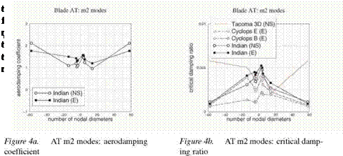
ResultsIn figures 4a and 4b, the same plots are presented for AT m2 modes. Again viscous effects seem to be not very important and INDIAN results agree well with CYCLOPS, especially with the“Cyclops E” curve. For low (positive and negative) nodal diameters the agreement is fairly good with TACOMA 3D results, as well.

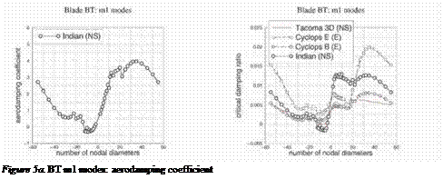
In figures 5a and 5b, results for BT m1 mode family are shown. For this blade, only Navier-Stokes based INDIAN results are presented. A generally good agreement is obtained between INDIAN, CYCLOPS and TACOMA;
Подпись:
again the agreement is better for backward traveling waves, and INDIAN tends to overestimate stability for positive nodal diameters.

Figure 5b. BT m1 modes: critical damp­

ing ratio

Results

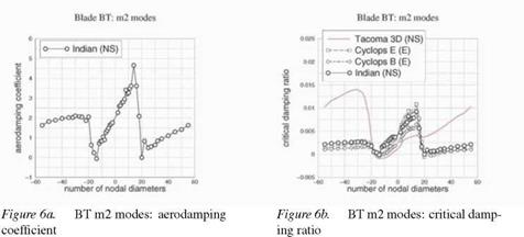
Finally, results for BT m2 modes are presented in figures 6a and 6b. Here agreement is satisfactory between INDIAN and CYCLOPS results. Compared with TACOMA solution, the trend is captured in the low nodal diameter re­gion, but the two flitter screening methods consistently over – or underpredict stability in the other regions.

2. Conclusions

A computational method for efficient complex mode flitter screening was described.

This approach exploits a set of aeroelastic time-linearized calculations in order to predict flitter stability of any specified complex mode of the analyzed bladerow and of similar ones. The method was developed for turbomachinery

bladerow design and was applied to two low pressure turbine rotor rows, for test and comparison purposes. From these results it was concluded that the method agrees well with the similar one described in [Kielb and Barter, 2003] for the majority of the examined modes. Both methods were also compared with a 3D time-linearized direct analysis: since they sometimes overestimate aeroelastic stability, flitter screening methods are not always conservative, so they are suitable for preliminary design, but further and more accurate analysis is required during design refinement. Additionally it was found that viscous effects are not very infbent on flitter stability.

Future work is needed to understand if disagreement between flitter screen­ing and 3D calculations is caused by the approximation method adopted to reduce 3D fbxible modeshapes to 2D rigid ones.

Acknowledgments

The authors wish to acknowledge Avio for the financial support and the permission to publish. Special thanks to Prof. E. Camevale (University of Florence) for encouraging this work. The authors wish also to express their gratitude to Prof. R. E. Kielb (Duke University) and J. Barter (GE) for provid­ing testcase data and for some useful suggestions.

Appendix: Normalization for work

Let cw be the aerodynamic work coefficient (that is, the aerodynamic work per unit span divided by mean inlet dynamic pressure and by squared chord).

The aerodamping coefficient is where A represents the vibration non-dimensional ‘amplitude’.

In the traditional definition (see [Boles and Fransson, 1986]) A is the angular amplitude (in radians) for pure torsion or the translational amplitude (divided by the chord) for pure bending. When we deal with arbitrary rigid modes, we must define A in such a way to be consistent with the two mentioned extreme cases, while remaining smooth in the whole range of possible modes. We define

А = Г^кф (A.2)

where кф is the torsional coefficient in the linear combination that defines the mode under examination and / is an appropriate correction factor.

For real modes / must be continuous and positive real (so that it cannot affect the sign of the aerodamping), must tend to one when the torsion axis location Q gets near the airfoil and must tend to zero when Q gets infinitely far from the airfoil in such a way that fDq —► 1 where Dq is the distance of Q from the airfoil, normalized by the chord.

The correction factor proposed by Panovsky and Kielb [Panovsky and Kielb, 2000] is

where xN and yN are two normalized coordinates such that the airfoil LE and ТЕ are placed in (0, 0) and (1,0), respectively. With this factor the desired goal of consistency is not quite reached, since fppDq —> 1/4.

Подпись: /43 Подпись: 4 3 + fpK Подпись: (A.4)

An alternative, fully consistent, correction factor is given by

For complex modes / must be again continuous and positive real and must tend to real mode / when the complex mode degenerates to a real one. For real modes XQ and yq were of course real and derived from the three linear combination real coefficients that describe the vibration mode (hx, hy and hy). In order to extend the correction factor definition to complex modes, we can derive two complex quantities (xq and yq) in a formally identical way, exploiting hx, hy and hy (that are now complex). These two quantities are not coordinates of a point, since they are complex, but their moduli can be used in the previous formulae to compute generalized correction factors.

References

Arnone, A. (1994). Viscous analysis of three-dimensional rotor fbw using a multigrid method. Journal of turbomachinery, 116:435-445.

Boles, A. and Fransson, T. H. (1986). Aeroelasticity in turbomachines Comparison of theoreti­cal and experimental cascade results. Number 13 in Communication du laboratoire de ther – mique appliquee et de turbomachines de Гесоїе polytechnique federale de Fausanne. EPFF.

Fransson, T. H. and Verdon, J. M. (1991). Updated report on “standard configurations for un­steady fbw through vibrating axial-fbw turbomachine-cascades”, <http://www. egi. kth. se/ proj/Projects/Markus%20joecker/STCF/STCFltol0/Documents/SC2110.92update. pdf>.

Giles, M. (1988). Non-refbcting boundary conditions for the euler equations. <http://web. comlab .ox. ac. uk/oucl/work/mike. giles/psfiles/bcs. ps. gz>.

Hall, K. C. and Clark, W. S. (1993). Finearized euler predictions of unsteady aerodynamic loads in cascades. AIAA Journal, 31:540-550.

Holmes, D. G., Mitchell, B. E., and Forence, C. B. (1997). Three dimensional finearized navier – stokes calculations for flitter and forced response. In 8 th International Symposium on Un­steady Aerodynamics and Aeroelasticity in Turbomachines.

Kielb, R. E. and Barter, J. (2003). Flutter design of lpt blades with cyclic symmetry modes – complicating effects. Submitted to ISUAAAT 2003 Conference.

Kielb, R. E., Barter, J., Chernysheva, O., and Fransson, T. H. (2003). Flutter of low pressure turbine blades with cyclic symmetric modes – a preliminary design method. In IGTIASME Turbo Expo.

Marshall, J. G. and Imregun, M. (1996). A review of aeroelasticity methods with emphasis on turbomachinery applications. Journal of fluids and structures, 10:237-267.

Panov sky, J. and Kielb, R. E. (2000). A design method to prevent low pressure turbine blade flitter. Journal of engineering for gas turbines and power, 122:89-98.

Tchernycheva, O. V., Fransson, T. H., Kielb, R. E., and Barter, J. (2001). Comparative analysis of blade mode shape infhence on flitter of two-dimensional turbine blades. In XVISOABE conference.

Flutter screening for complex modes

In applying flitter screening to complex modes, a similar approach is fol­lowed.

The rigid complex mode is described as a complex —instead of real— coef­ficient linear combination of the same three fundamental modes: the pressure perturbation on a generic complex mode (at a given IBPA and frequency) is de­rived by linearly superposing the three fundamental real perturbations solved for the generation of real mode flitter maps.

Note that the generic complex mode is assigned as the sum of two real modes in quadrature with a specified amplitude ratio. This non-unique description of the mode is converted into a unique complex coefficient linear combination of the three fundamental modes, and the complex mode pressure perturbation and the aerodynamic work are consequently derived. The aerodynamic work normalization is consistently extended from real to complex modes, through an appropriate “complex mode amplitude” (see appendix).

In the above described approach to complex mode screening no simplify­ing assumptions are introduced [Kielb et al., 2003]: all contributions to the aerodynamic work are taken into account (those combining the unsteady pres­sures generated by one harmonic component to the displacements of the same harmonic component, those combing the unsteady pressures generated by one harmonic component to the displacements of the other harmonic component, as well as the mean pressure contribution).

Moreover, since a complex mode is specified through four real parameters (two complex coefficient ratios) rather than two (two real coefficient ratios), a two-dimensional flutter map is not suitable for complex mode flutter stability assessment.

Hence, when dealing with complex modes, mode-specific outputs are gen­erated. In particular, for each prescribed complex mode:

1 the aerodynamic damping coefficient (at each IBPA and frequency for which input data have been provided),

2 the stability parameter (at each frequency for which input data have been provided),

3 the critical reduced frequency,

4 the aerodynamic damping coefficient at a specified IBPA (at each fre­quency for which input data have been provided), obtained by exploiting the aerodamp sinusoidal approximation,

5 the critical reduced frequency at a specified IBPA.

Flutter screening for real modes

Before applying flitter screening to complex modes, real mode screening has been implemented, through the integration of LARS with a specific pro-

gram developed at Department of Energy Engineering (University of Florence). This program is called INDIAN (INtegrated & Distributed ANswer).

A detailed description of real mode flutter screening is not the aim of this paper, but the procedure will be briefly reviewed, because it represents the baseline scheme in the development of complex mode flitter screening.

An arbitrary real rigid vibration mode can be described as a real coeffi­cient linear combination of three fundamental real modes, and the aerodynamic work can be expressed as a quadratic form of these coefficients. Once the 3 x 3 work matrix has been derived, the evaluation of the aerodynamic work for any real mode is straightforward and very efficient.

The aerodynamic work is then normalized to obtain the aerodynamic damp­ing coefficient. This normalization is defined through a (squared) vibration amplitude, identified in such a way to achieve consistency with the traditional definitions of damping coefficient in the two particular cases of pure bending and pure torsion. In the appendix a fully consistent normalization is derived, al­ternative to that proposed by Panovsky and Kielb [Panovsky and Kielb, 2000].

In the LARS-INDIAN based screening procedure:

1 aeroelastic calculations are carried out on two pure bending modes along orthogonal directions and one pure torsion mode, selected as fundamen­tal modes, at prescribed interblade phase angles (IBPAs) and vibration frequencies, covering the respective ranges of variation;

2 fundamental perturbations are combined, so that the work and aerody­namic damping for any arbitrary torsion axis location can be derived;

3 the generation of several flutter maps, applicable in real mode flitter screening, is allowed, namely:

■ aerodamping maps, providing the aerodynamic damping coeffi­cient as a function of torsion axis location —or bending direction— for a given IB PA and vibration frequency,

■ stability maps, providing the stability parameter (defined as the minimum of the aerodynamic damping sinusoidal approximation over the range of IB PA variation) as a function of torsion axis lo­cation —or bending direction— for a given frequency,

■ critical reduced frequency maps, providing the reduced frequency below which the stability parameter becomes negative as a function of torsion axis location —or bending direction—.

Computational method

Aim of this paper is to present a method to assess flitter stability of complex modes. As in the P-K method, the blade modeshape is approximated to a rigid motion and the row vibrates in traveling wave mode. Additionally, as in P-K, a single section of the blade (e. g. the one with the greatest displacements) is used to represent the blade 3D vibration mode.

Aeroelastic solver

During our research on Computational Aeroelasticity (CA) at the Depart­ment of Energy Engineering (University of Florence), we developed an aeroe­lastic solver, designed to work together with the steady/unsteady fl»w solver TRAF [Arnone, 1994].

This aeroelastic solver (named LARS, time-Linearized Aeroelastic Response

Solver) is based on the uncoupled energy approach: the blade harmonic oscil­lation is prescribed in terms of frequency and modeshape, and flitter stability is assessed through a work per period calculation. Quasi-three-dimensional fliid motion equations (Euler, thin shear layer or Navier-Stokes) are time-linearized about a steady solution [Hall and Clark, 1993]; this steady solution, represent­ing the mean fl>w, is computed by TRAF in steady mode, while its harmonic perturbation, representing the fbw field unsteadiness generated by blade har­monic motion, is calculated by LARS.

Numerical stability is guaranteed through the introduction of appropriate artificial dissipation, derived from TRAF definition through frozen coefficient linearization. In order to speed up convergence, local time stepping, multigrid acceleration and residual smoothing techniques have been implemented in a way similar to that adopted for TRAF. Non-reflecting boundary conditions are used on inlet and outlet boundaries [Giles, 1988].

The solver implements both traveling wave mode and influence coefficient technique; in this work the traveling wave mode has been applied.

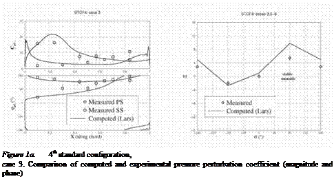
Подпись: Figure 1a. 4th standard configuration, case 3. Comparison of computed and experimental pressure perturbation coefficient (magnitude and phase)
LARS was previously validated for turbine blades applications on Interna­tional Standard Configuration turbine experimental data [Fransson and Verdon, 1991], in particular STCF4 (see figures 1a, 1b).

Figure 1b. 4th standard configuration,

cases 3, 6, 7, 8. Comparison of computed and experimental aerodamping coefficient