Category UNSTEADY AERODYNAMICS, AEROACOUSTICS AND AEROELASTICITY OF TURBOMACHINES

A METHOD TO ASSESS FLUTTER STABILITY OF COMPLEX MODES

Andrea Arnone1, Francesco Poli1, and Claudia Schipani2

1 “Sergio Stecco” Department of Energy Engineering

University of Florence

Via S. Marta, 3 – 50139 Florence, ITALY

2Avio – R&D

Via Nizza, 312 -10127 Turin, ITALY

Abstract A method to quickly predict aeroelastic stability or instability of blade row com­

plex vibration modes is described. The computational approach is based on a time-linearized Navier-Stokes aeroelastic solver, and a specifically developed program. Time is saved by doing a few fundamental solver computations and then superposing the solutions to analyze each complex mode.

Test results on two low pressure turbines are presented.

Keywords: Flutter screening, complex modes, preliminary design, time-linearized, aero-

elasticity

1. Introduction

Nowadays, important goals in the aero-engine design are weight and cost reduction, as well as reliability increase. These goals are reached by reducing the number of mechanical parts and by adopting thin and highly loaded blades. These trends increase the relevance of blade row vibration phenomena (flitter and forced response) that are recognized as a major cause of high cycle fatigue (HCF) failure in rotating as well as static components.

In recent years the attention of aero-engine industry has been focused on the development of advanced computational tools, that, combining CFD and struc­tural dynamic analysis, —more or less accurately— model the fliid-structure interaction, and, in particular, enable the assessment of flitter stability [Mar­shall and Imregun, 1996]. However these tools are computationally very ex­pensive and require detailed input data: thus their application is usually limited to the design validation phase, while they are not suitable for sensitivity and parameter studies, that are often needed during the preliminary design.

31

K. C. Hall et al. (eds.),

Unsteady Aerodynamics, Aeroacoustics and Aeroelasticity of Turbomachines, 31-40. © 2006 Springer. Printed in the Netherlands.

Less significant advances have been made for the development of design methods, that, adopting a simplified approach to the fliid-structure interaction modeling, but still relying on specifically developed computational tools, may be applied in the preliminary design, without loosing representativeness of the blade design under investigation.

The recent work by Panovsky and Kielb, proposing a design method to pre­vent LP turbine blade flitter [Panovsky and Kielb, 2000], is a well-known attempt in this direction. This method (P-K method) is based on the finding that flutter stability of a turbine blade vibration mode is not only depending on the mode frequency and blade aerodynamic operating condition, but also on the blade modeshape.

The flutter stability is still assessed by comparing the actual to critical reduced frequency, making the new method easily applicable. The critical reduced frequency, traditionally constant for a given mode typology (torsion or bend­ing), is derived from the blade torsion axis location —or bending direction—, while the actual reduced frequency is computed through the traditional for­mula, based on mode frequency and blade aerodynamic operating condition: k = uc/(2vout), where и is the angular frequency, c is the chord and vout is the outlet flow velocity.

On the other side the proposed method is limited to real modes in traveling waves. Real modes are single harmonic component modes: all points belong­ing to the same blade vibrate in phase (or antiphase) with each other.

This hypothesis is acceptable for elastically suspended uncoupled blades, but essentially excludes blade row assembly modes to be properly described.

This is the case for shrouded rotor rows, where the blade mechanical coupling generates the so-called complex modes, that can be seen as a superposition of two real modes in quadrature.

Far field domain

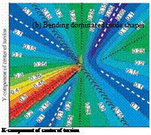
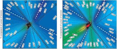
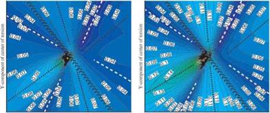
The descriptions of the results are given here with respect to the torsion axis location. This means that the torsion axis location approaching infinity along the chord-wise direction corresponds to a translation of the reference vane in the normal to the chord-wise direction. Similarly, a torsion axis lo­cation approaching infinity in the normal-to-chord direction is equivalent to a chord-wise bending. Thus, symmetry at infinity in the critical reduced fre­quency map about the reference vane is expected (Figs. 6-7). Furthermore, the stability prediction for bending-dominated modes become a complementary tool for clarification of the trends observed for the torsion-dominated modes.

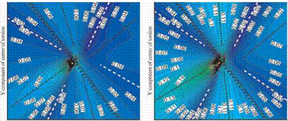
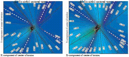
As for freestanding blade cascades (Fig. 2b) the critical reduced frequency maps for the four-, five – and six-airfoil sectored vanes (Figs. 5-6) have two most stable and two most unstable regions. The directions of these regions are somewhat similar to the freestanding blades despite the vibration ampli­tude distribution between the airfoils in the sector (Figs. 6-7). The number of airfoils in the sector does not, in general, affect the directions of the two most stable and two most unstable regions (Figs. 6a-c and 7a-c). The two most stable regions are perpendicular to each other (see dashed line in Figs. 6-7). The first unstable region (which is also the largest of the two unstable regions found) is orientated almost normal to the pitch-wise direction of the cascade (dotted line 1). The second region of lower stability lies somewhere parallel to the throat line of the reference vane (dotted line 2). As expected, the aero­dynamic damping level of the sectored vanes with the edge blade dominated (Figs. 7a-c) are higher than for the sectored vanes with the uniform vibration amplitude distribution (Figs. 6a-c). The critical reduced frequency values for the Case 2 amplitude distribution are varying between 0.03 and 0.17, while for the Case 1 those values are lying between 0.02 and 0.11.

Подпись: (a) Four-airfoil sectored vaneFar field domain
(a) Four-airfoil sectored vane

(b) Far field domain
Five-airfoil sectored vane (b) Five-airfoil sectored vane

Figure 6. Case 1 vibration amplitude distil – Figure 7. Case 2 vibration amplitude distri­bution (far field domain) bution (far field domain)

This is still much lower than the freestanding blade cascade which has crit­ical reduced frequency values between 0.05 and 0.5 (Fig. 2b).

Far field domain

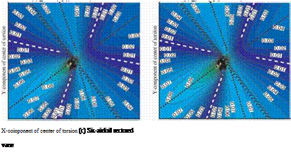
Soldier modes. Structural analysis shows that a vibration pattern with iden­tical amplitude and zero inter-blade phase angle is a typical mode shape for a sectored vane cascade at low reduced frequencies. The critical reduced fre­quency maps for the four-, five – and six-airfoil sectored vanes for this so-called "soldier mode” are shown in Figures 8a, 8b and 8c, respectively.

As for a more general case of real sector mode shapes (far-held domain, Case 1 amplitude distribution, referred to Figs. 6a-c) a presence of the two most stable and two most unstable regions is observed. The absence of the out-phase motions of the blades within the sector, that characterizes the soldier modes, does not affect the directions of the second region of stability and the two instability regions (Figs. 8a-c). While the angle between the largest stable region and the pitch-wise direction of the cascade increases up to 45 degrees.

As expected, the sectored vanes undergoing solder modes become even more stable, in comparison to a more general case of real sector mode shapes, with the range of the critical reduced frequencies between 0.01-0.11.

Thus, also for bending-dominated modes the similarity between the main stability and instability directions for the four-, five – and six-airfoil sectored vanes are observed. The differences in the level of aerodynamic damping are defined by the number of the airfoils in the corresponding sectored vane. As expected, increasing the number of airfoils in sector from four to six increases the aerodynamic stability of the cascade.

6. Conclusions

A model for performing a stability analysis towards a reduced frequency and sector mode shape variation has been applied to a low-pressure turbine sectored vane. A parametrical study summarizing the effect of the reduced frequency and sector mode shape has been carried out varying the vibration amplitude distribution between the airfoils in sector as well as the number of airfoils in sector. The main assumption is that the ft>w is isentropic and two-dimensional. Critical reduced frequency maps have been provided for torsion – and bending – dominated sector mode shapes and the following conclusions have been drawn.

Even though the absolute value of the average aerodynamic work is rather different between four-, five – and six-airfoil sectors a high risk for instability still exists in the neighborhood of realistic reduced frequencies of modern low – pressure turbine (critical reduced frequency between 0.2 and 0.3 for torsion – dominated modes, between 0.01 and 0.05 for bending-dominated modes).

For the cases studied it is observed that the sectored vane displacement with the edge airfoils in the sector dominating provides the most unstable critical reduced frequency map.

Increasing the number of blades in the sector decreases the risk for a sec­tored vane to be unstable for uniform or internal blades dominated amplitude distributions. The stability of the sectored vane with edge blades dominated amplitude distribution is not affected much by the number of blades in the sector.

7. Future work

To generalize the findings, similar parametric studies should be performed for another sectored vane geometry and for other fbw conditions.

An extension from single to multiple frequency modes can be introduced in the present algorithm. It would take into account the mode coalescence, i. e. even though every single frequency mode by itself can be stable, their cross products may make the multiple frequency mode to be unstable.

Acknowledgments

The authors wish to thank GE Aircraft Engines for the provision of NOVAK (2D Version 6.0), for financial support and for the permission to publish the findings. Thanks also to the Swedish Energy Authority for partial financial support of the first author.

References

Whitehead, D. S., and Evans, D. H., 1992, “Flutter of grouped turbine blades”, 92-GT-227, ASME Gas Turbine and Aeroengine Congress and Exposition, Cologne, Germany.

Kahl, G., 1995, “Application of the time linearized Euler method to flitter and forced response calculations”, ASME paper 95-GT-123.

Chernysheva, O. V., Fransson, T. H., Kielb, R., E., and Barter, J., 2003, “Effect of sec­tor mode shape variation on the aerodynamic stability of a low-pressure turbine sectored vane”, GT2003-38632, ASME/IGTI Turbo Expo, Atlanta, Georgia, USA.

Panovsky, J., and Kielb, R., E., 1998, “A design method to prevent low-pressure turbine blade flitter”, 98-GT-575, ASME Gas Turbine Conference and Exhibition, Stockholm, Sweden.

Tchernysheva, O. V., Fransson, T. H., Kielb, R., E., and Barter, J., 2001, “Comparative analysis of blade mode shape influence on flutter of two-dimensional turbine blades”, ISABE-2001-1243, XVISOABE Conference, Bangalore, India.

Lane, F., 1956, "System mode shapes in the flitter of compressor blade rows", Journal of the Aeronautical Science, Jan., pp. 54-66.

Holmes, D.,G., and, Chuang, H. A., 1991, “2D linearized harmonic Euler fbw analysis for flitter and forced response”, Unsteady Aerodynamics Aeroacoustics and Aeroelasticity of Turbomachines and Propellers, Springer Verlag, New York, pp. 213-230.

Near field domain

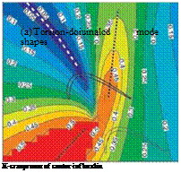
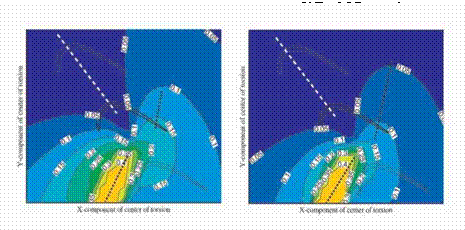
Comparing the present investigation with the findings for the freestanding blade (Fig. 2a), it is concluded from Figures 3 to 5 that the overall stability behavior of a sectored vane cascade of four, five or six blades, as well as the main directions, for the most stable and unstable regions, remains the same. These directions are also not affected by the different amplitude distributions

Near field domain
Near field domain

Figure 2. Freestanding blade cascade

from cases 1, 2, and 3. In all cases the stability of the reference sectored vane is more sensitive to a change in the pitching axis location along, rather than normal to, the surfaces of the airfoils.

The region of the most stable pitching axis locations begins slightly below the reference vane, passes its high curvature region and extends upwards along the pitch-wise direction of the cascade (see dashed line in Figs. 2a and 3-5). The most unstable direction (see dotted line in Figs. 2a and 3-5) of the pitching axis locations also begins below the reference vane and has two branches. One corresponding to a higher instability level is orientated upstream of the cascade approximately perpendicular to the cascade tangential direction. Another one with a lower level of instability passes the reference vane at approximately 60% true chord and is directed outside of the cascade normal to the aft part of the vane.

X-component of center of torsion


X-componenl of center of torsion


Near field domain

(a) Four-airfoil sectored vane

(a) Four-airfoil sectored vane

X-component of center of torsion


X-component of center of torsion


Near field domain

(b) Подпись: (b) Five-airfoil sectored vaneFive-airfoil sectored vane (a) Four-airfoil sectored vane

X-component of center of torsion


X-componenl of center of torsion


Near field domain

(c) Six-airfoil sectored vane

(c) Six airfoil sectored vane

Figure 3. Case 1 vibration amplitude distri – Figure 4. Case 2 vibration amplitude distri­bution (far field domain) bution (far field domain)

Near field domain
However, the absolute value of the average aerodynamic work is fairly dif­ferent between the freestanding blade and multiple-airfoil sectored vanes. None of the four-, five – or six-airfoil sectored vane has a region of as high gradients in critical reduced frequency along the mid-section of the reference vane as the freestanding blade. Furthermore, the stability increase for a sectored vane is clearly seen: the shape of the domain with unstable pitching axis locations that the multiple-airfoil sectored vanes have at k=0.25 (for Case 1 amplitude distribution, Fig. 3), at k=0.35 (for Case 2 amplitude distribution, Fig. 4) or at k=0.2 (for Case 3 amplitude distribution, Fig. 5) is achieved for the freestand­ing blade already at much higher reduced frequency of k=0.5 (Fig. 2a).

Figure 5. Case 3 vibration amplitude distribution (near field domain)

Increasing the number of airfoils in a sector clearly affects the absolute value of the average aerodynamic work of the sectored vane with uniform (Figs. 3a – c) or internal blade dominated (Figs. 5a-b) vibration amplitude distribution. For similar curved contour lines the values of the critical reduced frequency corresponding to these lines are higher for the sectored vane with a lower num­ber of airfoils in sector. In the domain near the aft part of the suction surface of the reference vane an increase in the number of blades from four to six leads to a decrease of 0.05 in the critical reduced frequency values. The size of the domain corresponding to the critical reduced frequency less than 0.05 is significantly larger for the six – than for the four-airfoil sectored vane. For the sectored vane displacement with the edge blades dominated (Figs. 4a-c) the infhence on the absolute value of the average aerodynamic work of the number of airfoils in the sector is much less.

A comparison of Figures 3 to 5 shows the effect of a vibration amplitude ratio between the edge and internal blades of the sector on the aerodynamic stability of the sectored vane. A change in the vibration amplitude distribu­tion from the uniform to the internal blades dominant stabilizes the sectored vane. While choosing the vibration amplitude with the edge airfoils dominant decreases the stability (Figs. 4a-c). The size of the domain with the critical re­duced frequency less than 0.05 becomes smaller. While near the aft part of the reference vane suction surface the maximum of the critical reduced frequency values increases.

Results and discussion

The vibration amplitude distributions between the airfoils in sector are cho­sen as for the following three cases:

h Uniform: all blades in sector vibrating with the same amplitude.

Z Edge blades dominated: vibration amplitude of the edge blades is 1 while the amplitude of the inner blades is 0.5.

T Internal blades dominated: vibration amplitude of the edge blades is 0.5 while the amplitude of the inner blades is 1.

The number of airfoils in a sector has been selected as four, five or six. While varying the real sector mode shape it is assumed that the mode shapes of the airfoils belonging to the same sector are changing in an identical manner.

The maps in Figures 2 to 8 show the values of the critical reduced frequen­cies. Each contour line in the critical reduced frequency map corresponds to the value of reduced frequency for which the reference vane is neutrally stable. The reference vane is in the center of the diagram and identified with a thicker line.

The discussion of the results is divided into two parts, for the torsion axis lo­cation varied in the near field of the reference vane (torsion dominated modes) and for torsion axis location approaching infinity (bending dominated modes).

A comparison of the aerodynamic behavior of the multiple airfoils sectored vanes is made against a freestanding blade cascade. In the freestanding blade cascade the blades vibrate with identical mode shapes as well as amplitudes and have a constant inter-blade phase angle between each other. The critical reduced frequency maps for the freestanding blade cascade are shown in Fig. 2a (torsion-dominated mode shapes) and in Fig. 2b (bending-dominated mode shapes) as a reference towards the four-, five – and six-airfoil sectored vanes to be shown later.

Sectored vane geometry and calculations in traveling wave domain

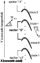
The stability analysis is performed for a sectored low-pressure gas-turbine vane cascade (Fig. 1) consisting of 15 sectors.

Подпись:pitch/c = 0.89 stagger = 350

P,= 43° 02=62°

= 0.39 MIS2 = 0.70

range of k: 0.005 – 0.4

Figure 1. Sectored vane geometry and parameters for the profile

Steady and unsteady calculations are performed with the linearized inviscid fttw solver NOVAK [7]. An overview of physical and aerodynamic parame-

ters for the aeroengine profile used for the calculations in the traveling wave domain is presented in Fig. 1. The basic calculations in the traveling wave domain are performed at 10 different inter-blade phase angles for the three fundamental modes, bending in two orthogonal directions and torsion.

Objectives

The present paper aims to investigate further the sensitivity of the critical (flitter) reduced frequency versus mode shape maps for the sectored vane, namely towards an non-uniform distribution in the amplitudes between the blades in the sector. The influence of the number of the airfoils in the sec­tored vane will be demonstrated.

2. Method of attack

The method for investigation of flitter appearance in a cascade, where blades are connected together in a number of identical sectors is presented in [3] and can be shortly described as follows:

• The aerodynamic response of a sectored vane is calculated based on the aerodynamic work influence coefficient representation of a freestanding bladed cascade.

• There is a possibility to consider different vibration amplitudes and any inter-blade phase angles for the blades in the sector, while the inter­sector phase angles follow the Lane’s criteria [6] and all blades have the same vibration frequency.

• Assuming a rigid-body motion allows to define the blade mode shape en­tirely by its pitching axis position. Thus, at a selected reduced frequency and given pitching axis positions for the blades in sector the aerody­namic work for the sector is calculated as a function of the inter-sector phase angle as well as amplitude and phase angle distributions between the airfoils in the sector. The absolute maximum of the work is then cal­culated and the algorithm is continued for another pitching axis position until the whole range of the mode shapes is covered.

• Afterwards, the results for a number of reduced frequencies are over­laid to produce a plot of critical reduced frequency versus pitching axis position for the reference sectored vane. This determines the value of reduced frequency for which each torsion axis locations of the blades in the sector becomes unstable.

For the practical applications shown in this paper the following restrictions are applied in the algorithm:

• Mode shape of the sectored vane is considered to be real, i. e. the blades in sector can only have 0 and/or 180 degree inter-blade phase angle be­tween each other.

• All the blades in the sector have the same relative pitching axis location.

In the present paper the method is applied for a number of different vibration amplitude distributions for the airfoils belonging to the same sector as well as for different numbers of airfoils in the sector.

INFLUENCE OF A VIBRATION AMPLITUDE DISTRIBUTION ON THE AERODYNAMIC STABILITY OF A LOW-PRESSURE TURBINE SECTORED VANE

Olga V. Chernysheva,1 Torsten H. Fransson,1 RobertE. Kielb,2 and John Barter3

1 Royal Institute of Technology S-100 44 Stockholm, Sweden olga@egi. kth. se fransson@egi. kth. se

2

Duke University Durham, NC 27708-0300, USA rkielb@duke. edu

3

3 GE Aircraft Engines,

Cincinnati, OH 45215-1988, USA john. Barter@ae. ge. com

Abstract A parametrical analysis summarizing the effect of the reduced frequency and sector mode shape is carried out for a low-pressure sectored vane cascade for different vibration amplitude distributions between the airfoils in sector as well as the numbers of the airfoils in sector. Critical reduced frequency maps are provided for torsion – and bending-dominated sector mode shapes.

Despite the different absolute values of the average aerodynamic work be­tween four-, five – and six-airfoil sectors a high risk for instability still exists in the neighborhood of realistic reduced frequencies of modern low-pressure tur­bine. Based on the cases studied it is observed that a sectored vane mode shape with the edge airfoils in the sector dominant provides the most unstable critical reduced frequency map.

Keywords: Flutter, sectored vane, sector mode shape, vibration amplitude distribution, crit­

ical reduced frequency.

17

K. C. Hall et al. (eds.),

Unsteady Aerodynamics, Aeroacoustics and Aeroelasticity of Turbomachines, 17-29. © 2006 Springer. Printed in the Netherlands.

Nomenclature

C

chord length

[m]

к

reduced frequency based on half-chord and outlet fbw velocity,

wc/( 2F2)

[-]

M

Mach number

[-]

V

fbw velocity

[m/s]

X

cascade axial co-ordinate

[-]

Y

Greek

cascade tangential co-ordinate

[-]

p

absolute fbw angle

[deg]

oj

Subscripts

circular frequency

[rad/s]

IS

isentropic

1

inlet

2

outlet

1. Introduction

In order to eliminate or reduce blade vibration problems in turbomachines, the adjacent airfoils around the wheel are often mechanically connected to­gether with either lacing wires, tip shrouds or part-span shrouds in a number of identical sectors. Such mechanical connections make the vibratory mode shapes much more complex. At the same time it allows a significant improve­ment in the stability margin of the design.

Numerical (see, for example, [1-3]) and experimental aerodynamic analy­sis has demonstrated the stabilizing effect. The numerical studies for sectored vanes presented in [1-2] were conducted with all blades in the sector vibrat­ing with the same frequency and amplitude and at different real mode shapes. The method used in [1] utilized the possibility of superposition for a linear system, the approach in [2] required calculations on a domain that covered as many passages as airfoils belonging to one sector. The findings were illustrated for selected sets of sectored vane modes for five – and six-airfoil low-pressure steam turbine sectored vanes in [1] and for three-airfoil low-pressure turbine sectored vane in [2]. Nevertheless, even though the sectored vanes benefited by the mechanical connection between vanes, flitter was still predicted for certain ranges of inter-sector phase angles.

According to structural analysis of a sectored vane displacement the blades in the sector might have different amplitudes, mode shapes and vibration fre­quencies which obviously affect the aerodynamic stability of the sectored vane. An important contribution of the blade mode shape into the aerodynamic sta­bility of the cascade has been already demonstrated in [4] for a freestanding low-pressure turbine blade with a real rigid-body mode shape. During the aeroelastic design phase, it was recommended to also study mode shape rather than only the reduced frequency of a blade. Further investigation, conducted in

[5] for a wide range of physical and aerodynamic blade parameters confirmed the findings and made it more general.

The approach presented in [3] employed, similarly to [1], the superposition assumption and, unlike [1], allowed a complex rigid-body mode shape with non-uniform amplitude distribution between the blades in a sector. The effect of real rigid-body sector mode shape variation on the aerodynamic stability of a low-pressure six-airfoil sectored vane was shown when all blades in sector were vibrating with identical amplitude. Although it was confirmed that tying blades together in a sector drastically improved the stability of the cascade, for some mode shapes sectored vane still remained unstable at relevant reduced frequencies.

Concluding Remarks

LPT blades are sometimes welded in pairs to increase their flitter charac­teristics. It has been shown by means of two-dimensional simulations that the aerodynamic damping welded-pairs is larger than the one of single blades. This specially true for torsion modes and bending modes whose flapping direction is aligned with the tangential direction of the cascade. A more in depth dis-

cussion of the theoretical benefits of using such configurations requires taking into account the frequency and three-dimensional mode shape modification.

The frequency characteristics of three bladed-disk configurations have been presented. The three assemblies differ just in the boundary conditions of the tip-shroud. It has been observed that the frequency characteristics of the welded – pair configuration are essentially the same that the cantilever configuration while the interlock changes dramatically the overall behaviour of the assem­bly. The prediction of the stability or not of the welded-pair configuration requires to account for three-dimensional and mistuning effects. The stability of the interlock is compromised by the transition between edgewise and tor­sion modes with the nodal diameter of the first family. It is believed that the torsion modes with low reduced frequency, that the 2D simulations show are unstable, are responsible of the instability, this is consistent with the results of other researchers.

Acknowledgments

The authors wish to thank ITP for the permission to publish this paper and for its support during the project. This work has been partially funded by the Spanish Minister of Science and Technology under the PROFIT grant FIT – 100300-2002-4 to the School of Aeronautics of the UPM.

References

Corral, R., Burgos, M. A., and Garcia, A., “Inflience of the Artificial Dissipation Model on the propagation of Acoustic and Entropy Waves”, ASME Paper 2000-GT-563, 2000.

Corral, R., Escribano, A., Gisbert, F., Serrano, A., and Vasco, V., “Validation of a Linear Multi­grid Accelerated Unstructured Navier-Stokes Solver for the Computation of Turbine Blades on Hybrid Grids”, AIAA Paper 2003-3326, 2003.

Corral, R., and Gisbert, F., “A Numerical Investigation on the Inflience of Lateral Boundaries in Linear Vibrating Cascades”, ASME Paper 2002-GT-30451, 2002.

Giles, M. B., “Non-refhcting Boundary Conditions for Euler Equation Calculations”, AIAA Journal, Vol. 28, No. 12, pp. 2050-2057, 1990.

Jameson, A., Schmidt, W., and Turkel, E., “Numerical Solution of the Euler Equations by Finite Volume Techniques using Runge-Kutta Time Stepping Schemes”, AIAA Paper 81­1259,1991.

Nowinski, M., and Panovsky, J., “Flutter Mechanisms in Low Pressure Turbine Blades”, Journal of Engineering for Gas Turbines and Power, Vol. 122, pp. 82-88, 2000 Panovski, J., and Kielb, R. E., “A Design Method to Prevent Low Pressure Turbine Blade Flut­ter”, Journal of Engineering for Gas Turbines and Power, Vol. 122, pp. 89-98, 2000 Roe, P., “Approximate Riemman Solvers, Parameters, Vectors and Difference Schemes”, Jour­nal of Computational Physics, Vol. 43, pp. 357-372, 1981.

Sayma, A. I., Vahdati M., Green, J. S., and Imregun, M., “Whole-Assembly Flutter Analysis of a Low Pressure Turbine Blade”, in Proceedings of the 8th International Symposium in Unsteady Aerodynamics and Aeroelasticity of Turbomachines, pp. 347-359, Edited by T. H., Fransson, 1998

Swanson, R. C., and Turkel, E., “On Central-Difference and Upwinding Schemes” Journal of Computational Physics, Vol. 101, pp. 292-306, 1992.

Modal Characteristics of Bladed-Disks

The aim of this section is to elucidate in a qualitative manner how the previ­ous results inflience the stability of realistic bladed-disk configurations and in particular to discuss the relative merit of using cantilever, interlock or welded – pair configurations. Although there exists a big leap in moving from pure 2D to fully 3D mode shapes the simplicity of the approach makes the exercise still attractive.

The bladed-disk assembly considered in this study is representative of the first stages of modern LPTs. A global view of the whole assembly may be seen in figure 6. The vibration characteristics of the cantilever, interlock and welded-pair configurations has been obtained with the same grid. The bound­ary condition in the contact nodes between sliding parts, namely, between the disk and the blade in the attachment, and between the shroud contacts in the interlock configuration enforces that the displacements of these in both sides are identical. This simplifying hypothesis is made to avoid the generation of non-linear models where the concepts of natural frequency and mode-shape need to be re-interpreted.

Since only the first two families are usually relevant for flitter studies we have restricted ourselves to the lowest range of the frequency – nodal-diameter diagram. Two analysis were carried out, firstly at rest and ambient tempera­ture and secondly at the operating sped with the associated temperatures. Only slight differences were seen in this particular case because the increase in stiff­ening due to the centrifugal force was compensated by the decrease in the Young’s module due to the increase in the inlet temperature of the turbine at the operating conditions. Since both results were very similar and to avoid further complications, the results presented correspond to the ones obtained at rest. The figure 7 shows the frequency characteristics of the first families for the cantilever (top), welded-pair (middle) and interlock (bottom) configu­rations. Several conclusions may be drawn upon inspection of this figure and the mode-shapes, not shown here for the sake of brevity,

1 The disk is very stiff compared to the blades. This may be seen in the mode-shapes, that show very small displacements of the disk, and in the frequency nodal diameter diagram that displays a high number of modes with nearly the same frequency within the same family.

2 The welded-pair configuration has slightly higher frequencies than the cantilever one with the exception of the third family that corresponds to the first torsion (1F) mode whose frequency drops.

3 The interlock provides and effective means to raise the frequencies of the assembly. The lower nodal diameters of the first family correspond to shroud dominated modes.

Modal Characteristics of Bladed-Disks

Figure 7. Modal characteristics of the bladed-disk assembly. Left: cantilever. Middle: Welded-pair. Right: Interlock

The baseline (cantilever) configuration is likely to be unstable since the re­duced frequency of the first fhp mode is too low, the first torsion mode is probably unstable a well. The welded-pair configuration is better from a flitter point of view than the cantilever one, the torsion mode will be stable in spite of having a lower reduced frequency, however, although the frequency of the 1st fhp mode is slightly higher than before, according with with the 2D inviscid results the mode is still unstable although the damping coefficient for the most unstable inter-blade phase angle has been reduced to one third of the original baseline configuration. This means that to predict absolute flutter boundaries three-dimensional and mistuning effects need to be retained.

The interlock configuration raises significantly the natural frequencies of the bladed-disk and hence is an effective mechanism as well to prevent flitter. A very similar interlock configuration was analyzed by Sayma et al. (1998), they found that the 6-12 nodal diameters, which corresponds in figure 7 (bot­tom) to 20% of the maximum nodal diameter, were unstable confirming pre­vious engine testing. A plausible explanation may be found by noting that the modes corresponding to the low diameter nodes of the interlock configuration are edgewise modes, which are stable, while the modes corresponding to the high diameter nodes are torsion modes, whose stability depends on the reduced frequency but that figure 3 (right) shows that is stable. The instability is con­centrated in the region where the edgewise modes become torsion modes and the reduced frequency is not high enough to ensure their stability.

Flutter Stability Maps

Panovski and Kielb (2000) showed, using flitter stability maps, how the modeshape and the reduced frequency were the basic parameters that con­trolled the stability of a two-dimensional LPT section. In practice only the mode-shape is relevant from a design perspective since the possible range of variation of the reduced frequency is very limited. We have extended such analysis to pairs of airfoils moving as a rigid body. The aim is to mimic the mode shapes obtained when pairs of blades are welded to increase the aero­dynamic damping of the bladed-disk assembly. The edgewise and flap modes are defined as bending modes along and perpendicular to the line that joins the leading and trailing edges, respectively. The center of torsion of the third fundamental mode is located at the l. e. of the airfoil, when pairs of blades are considered the pair is formed adding a new airfoil adjacent to the pressure side of the reference airfoil and the center of torsion of the fundamental node is kept at the l. e. of the reference section. The airfoil used in all the simulations

Flutter Stability Maps

Figure 4. Flutter stability maps for the single blade configuration. The shadow regions rep­resent the locus of the stable torsion centres

corresponds to the mid-section of a representative rotor blade (ainlet = 37°, aexit = 64°, MiS = 0.76).

Figure 3 displays the damping coefficient as a function of the IBFA for the different fundamental modes previously described. For both configurations it may be seen the stabilizing effect of the reduced frequency although for the single blade configuration there always exists a region of unstable IBPA for the computed range of reduced frequencies. The stabilizing effect of the welded – pair configuration may be clearly seen at the bottom of the same figure. In this case all the fundamental modes are stable for k = 0.4 being the fhp mode the most critical one. The torsion mode is highly stabilised for the welded-pair configuration and becomes neutrally stable for k = 0.1.

The damping curves of the fundamental modes have been fitted to a sine curve and the methodology described in the previous section used to construct the stability maps for both configurations to conduct a complete study of mode shape in a practical and systematic manner.

Figure 4 shows the flitter stability maps for the single blade configuration, the middle section represents the reference section and the shadow regions the locus of the stable torsion centres. It may be appreciated firstly how the airfoil is intrinsically unstable in torsion and secondly how increasing the reduced

Flutter Stability Maps

Figure 5. Flutter stability maps for the welded-pair configuration. The shadow regions repre­sent the locus of the stable torsion centres

frequency the stable region is enlarged. It is worth noting as well that while the axial mode (bending in the x direction) is stable the fhx mode (bending in the y direction) is unstable, this may inferred by realizing that a torsion axis at infinity (y ^ ж for instance, which is a stable region) generates a pure axial bending stable mode.

Figure 5 shows the equivalent map for a pair of airfoils moving as a rigid body. The upper airfoil of the pair corresponds to the upper section of the figure. The increase of the aerodynamic damping with respect the single blade configuration is clearly seen and for k = 0.4 the airfoil is stable in torsion modes whose centre of torsion is in the vicinity of the blade and in a wide range of bending directions, the only unstable mode is the fhx mode.

Only qualitative comparisons are possible with the results obtained by the research efforts of Panovski & Kielb (2000) since neither the geometry nor all the aerodynamic conditions are available, still it may be concluded that the basic steady aerodynamic conditions are comparable in first approximation and the stability map of both cases is similar as well confirming the idea that the sensitivity to the geometry and aerodynamic conditions is low.

Flutter Stability Maps

Figure 6. Global view of the the bladed-disk assembly configurations