The Human Pilot
Although the analysis and understanding of the dynamics of the airplane as an isolated unit is extremely important, one must be careful not to forget that for many flight situations it is the response of the total system, made up of the human pilot and the aircraft, that must be considered. It is for this reason that the designers of aircraft should apply the findings of studies into the human factors involved in order to ensure that the completed system is well suited to the pilots who must fly it.
Some of the areas of consideration include:
1. Cockpit environment; the occupants of the vehicle must be provided with oxygen, warmth, light, and so forth, to sustain them comfortably.
2. Instrument displays; instruments must be designed and positioned to provide a useful and unambiguous flow of information to the pilot.
3. Controls and switches; the control forces and control system dynamics must be acceptable to the pilot, and switches must be so positioned and designed as to prevent accidental operation. Tables 1.1 to 1.3 present some pilot data concerning control forces.
4. Pilot workload; the workload of the pilot can often be reduced through proper planning and the introduction of automatic equipment.
|
Table 1.1 Estimates of the Maximum Rudder Forces that Can Be Exerted for Various Positions of the Rudder Pedal (BuAer, 1954)
|
|
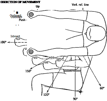
Table 1.2 Hand-Operated Control Forces (From Flight Safety Foundation Human Engineering Bulletin 56-5H) (see figure in Table 1.3)
Note: The above results are those obtained from unrestricted movement of the subject. Any force required to overcome garment restriction would reduce the effective forces by the same amount. |
|
Table 1.3 Rates of Stick Movement in Flight Test Pull-ups Under Various Loads (BuAer, 1954)
|
 |
The care exercised in considering the human element in the closed-loop system made up of pilot and aircraft can determine the success or failure of a given aircraft design to complete its mission in a safe and efficient manner.
Many critical tasks performed by pilots involve them in activities that resemble those of a servo control system. For example, the execution of a landing approach through turbulent air requires the pilot to monitor the aircraft’s altitude, position, attitude, and airspeed and to maintain these variables near their desired values through the actuation of the control system. It has been found in this type of control situation that the pilot can be modeled by a linear control system based either on classical control theory or optimal control theory (Etkin, 1972; Kleinman et al., 1970; McRuer and Krendel, 1973).


