Category Theoretical and Applied Aerodynamics

Special Techniques

A.1 Methods of Complex Variables

Solutions of two-dimensional, incompressible, potential flow problems can be obtained using functions of complex variables. In the following we follow Moran [1] and others [2].

A complex number z consists of two real numbers x and y, where

z = x + iy, Z = x – iy, i = 1 (A.1)

Special Techniques
or

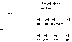
Подпись: d w ,дф дф dz - дy + дy Hence, дф , дф , дф дф дх + 1 дх - д у + д у or дф дф дф дф дх д у ’ д у дх Special Techniques

On the other hand, if Az = i Ay, then

The two conditions of Eq. (A.9) are known as the Cauchy-Riemann equations. In general, since x = (z + z)/2 and у = (z — z)/2i, w(x, y) = w(z, z). In fact

Подпись:дw 1 дф дф i дф дф

дz 2 дх д у + 2 д у + дх

Therefore, for analytic functions, дw/дz = 0, i. e. w is a function of z only.

If w(z) possesses a derivative at z = z0 and at every point in some neighborhood of z0, then w(z) is said to be analytic.

Let

Подпись:дф дф дф дф

дх д у ’ д у дх

then

= u — i v (A.12)

dz

is the complex velocity.

Special Techniques Подпись: (A.13)

It will be shown later that the derivative of an analytic function is also analytic function and hence an analytic function possesses derivatives of all orders and can be represented by convergent Taylor series at any point in the region where the function is analytic (the radius of convergence is determined by the closest point where the function fails to be analytic, i. e. the closest singular point). It follows then for any analytic function w

However,

d2 w 1 д2ф д2ф i d2 ф д2ф

dzdz 4 dx2 + dy2 + 4 dx2 + dy2 ^ ( • )

hence, ф and ф satisfy Laplace equation.

Since, dw/dz is also analytic function, then Eq. (A.12) implies

du dv du dv

dx dy ’ dy dx (A.15)

The first of Eq. (A.15) is the continuity equation and the second is the irrota – tionality condition. Hence ф and ф are the potential and stream functions of two­dimensional incompressible, irrotational flows and w(z) = ф(x’ y) + iф(x’ y) is called complex potential. Both the real and the imaginary parts of the above analytic function have continuous second partial derivatives satisfying Laplace’s equation

Подпись:д2ф д2 ф д2ф д2ф

dx2 + dy2 0 dx2 + dy2

Moreover, the curves of the family ф(x’ y) = constant are the orthogonal tra­jectories of the curves of the family ф (x’ y) = constant, (and vice versa if ф and ф satisfy Laplace equation, then w(z) is an analytic function).

Examples of complex potential are

(i)

w = Ue iaz = U(x cos a + y sin a) + iU(y cos a – x sin a) (A.17)

The above expression represents the potential and stream functions of a uniform flow making an angle a with the x-axis.

(ii)

1

w = (Q + i Г) ln z (A.18)

2n

This w represents the complex potential of a source of strength Q and a potential vortex of strength Г at the origin.

Special Techniques Подпись: (A.19)

(iii)

Special Techniques
Подпись: (A.23)
Подпись: (A.24)

In analytic mapping, the length of infinitesimal segments are altered by a factor I ddW I which depends only on the point from which the segments are drawn (regardless

of the direction). The infinitesimal areas are then magnified by the factor | ddW |2, i. e. by J.

Also, two infinitesimal segments forming an angle will both be rotated in the same direction by the same amount. A transformation which preserves the sense and the magnitudes of angles is said to be conformal. Hence, any analytic function W = W(Z) defines conformal transformation (as long as dW = 0).

An important theorem of conformal mappings is the following: Laplace equation is transformed to a Laplace equation, for example, consider the one-to-one trans­formation z = z(Z), its inverse Z = Z(z) and the complex potential W(Z) =

Special Techniques Special Techniques Подпись: (A.25)

Ф(Х, Y) + iФ(X, Y) = w(z) = ф(х, у) + iф(х, y) hence,

in the Z-plane, are transformed to

Подпись:д2ф d2 ф д2ф д2ф

дх2 + ду2 дх2 + ду2

in the z-plane (where ddZ = 0). Moreover,

ф(х, у) = ф(Х, Y), ф(х, у) = V(X, Y), w(z) = W(Z) (A.27)

The proof is based on the fact that an analytic function of an analytic function is analytic, see [3].

It can be also shown that the kinetic energy of the motion remains constant under conformal transformation, see [2].

Let the derivatives of the complex potentials with respect to z and Z be dw/dz and dW/dZ.

Since W = w,


Подпись:dW dw dz dw dW dZ dZ dz dZ ’ dz dZ dz

Подпись: Hence, using the chain rule Special Techniques Special Techniques

The complex velocity in the Z-plane is defined as

Подпись: dw dW dZ dz dZ dz Подпись: |u — i v| Подпись: |U Подпись: iV| Подпись: dZ dz Подпись: (A.31)

The equality of the moduli yields

hence the velocity magnitude can be found in the physical plane. Since the ratio of two incremental areas in Z – and z-planes is equal to the Jacobian, hence the integral over corresponding domains of the kinetic energy for constant density flows is preserved. Using Bernoulli’s law, this relation can be used to find the pressure distribution anywhere in the physical plane.

Special Techniques Special Techniques

The simplest example of conformal transformation is mapping the circle to a slit, given by

Подпись: W = U (Z + є Special Techniques

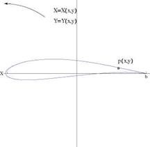
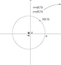
The cylinder of radius r0, centered at (—e, 6) in the Z-plane, passing by the point B (a, 0), maps onto a Joukowski profile, with cusped trailing edge at point b, Fig. A.2. Special cases correspond to є = 0 and/or 6 = 0. In the Z-plane, the flow at angle a with the X-axis, about the circular cylinder, is given by the complex potential

Special Techniques

Special Techniques

Fig. A.2 Z-plane (left); г-plane (right)


y


X


Special Techniques

Подпись: u — i v Подпись: dW dZ dZ dz Special Techniques
Special Techniques

The complex velocity in the physical plane is given by

There is a singularity at Z = ±a. The singularity at Z = a on the cylinder, is needed to have a cusped airfoil, while the singularity at Z = —a inside the cylinder, is excluded from the domain of interest.

The Kutta-Joukowski condition requires that velocity to be finite at the trailing edge, hence the numerator should vanish at Z = a, meaning that the point is a stagnation point for the flow past the circular cylinder. The condition reads

Г = 4nU ((a + e) sin a + S cos a) (A.36)

Подпись: u — i v = UПодпись: (A.37)

Special Techniques

Note that the condition obtained is the same for the real and imaginary parts of the complex equation dW(a)/dZ = 0 because the flow is constrained to be tangent to the cylinder. After some algebra one finds

There are two important special cases:

(i) e = S = 0, for a flat plate at angle of attack. In this case, r0 = a, z = aeie and

(ii) є = 0, 6 = 0 (say 6 > 0), for a circular arc at angle of attack. In this case, r0 = Va2 + 62, and

Г = 4nU (a sin a + 6 cos a) (A.39)

Cauchy Integral Theorem

The Cauchy integral theorem states that the line integral of analytic function in a simply connected region S around a closed curve C in this region, is zero, i. e.

У w(z)dz = 0 (A.40)

To prove the theorem, let w(z) = ф + iф and z = x + iy, hence

w(z)dz = (ф + i ф)(dx + idy) (A.41)

The integral can be expanded as

w(z)dz = (фdx – фdy) + i (фdx + фdy) (A.42)

C C C

Using Green’s theorem with domain D inside curve C

<j> (фdx – фdy) = – j J dxdy = 0 (A.43)

У (фdx + фdy) = — У У dxdy = 0 (A.44)

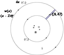
An extension of Cauchy theorem for multiply connected domain where C1 and C2 are closed curves in the region that can be continuously deformed into each other without leaving the region, is given by

w(z)dz – w(z)dz = 0 (A.45)

C1 C2

SeeFig.A.3.

Based on Cauchy theorems, one can show that

1 w(z)

w(z0) = dz (A.46)

2ni z – z0

where z0 is any point in the interior of the simply connected region R whose boundary is sectionally smooth. Moreover, the derivative of w(z) at point z0 is given by
Подпись: Fig. A.3 Contour for multiply connected region Special Techniques
Подпись: 1 2ni
Подпись: w'(Z0)

Higher derivatives can be obtained formally by repeated differentiation with respect to z0. Finally, the converse of Cauchy theorem is true, namely if w(z) is a continuous function in a region R and if / w(z)dz = 0 for every simple closed curve C which can be drawn in R, then w(z) is analytic in R, see Ref. [4].

Blasius Theorems

The pressure force acting on an element of surface is pds. Assuming unit width, the components in x and y directions are

dFx = – pdy, dFy = pdx (A.48)

Hence, if one defines dF = dFx – idFy, then

dF = – ip(dx – idy) (A.49)

According to Bernoulli formula, p = p«, + pU2/2 – pV2/2 and V2 = (u – iv)(u + iv). On a closed contour, the constant pressure term pOT + pU2/2 does not contribute to the force. Therefore, the elementary force due to pressure reduces to

p

dF = i (u – iv)(u + iv)(dx – idy) (A.50)

But, the complex velocity is related to the complex potential w(z) by

dw

= u – i v (A.51)

dz

Hence

The body contour is a streamline along which dw is real since dгф quently, dw is equal to its complex conjugate and can be written as

= 0. Conse-

d w = (u + i v)(dx — idy)

(A.53)

Hence

p dw p (dw)2

dF = dFx — idFy = i d w = i dz x y 2 dz 2 dz

(A.54)

The elementary moment about the origin can also be found from

dM, o = —— {izdF}

(A.55)

with the moment counted positive clockwise.

Upon integration around the obstacle one obtains

F = i P /(dw )2 dz

(A.56)

M, o=2— {/z (dz) 4

(A.57)

These integrals of analytic functions along closed contour can be evaluated with the theorem of residues.

Подпись: d w 2 dZ) Подпись: , , A1 , A2 , . An , A0 + + 2 + ••• + П + ” z z2 zn Подпись: (A.58)

Far from the obstacle, the velocity perturbation dies out as the flow returns to uniform flow condition. The complex potential can be expanded in a series of inverse powers of z, as

Special Techniques

Using as integration contour a large circle of radius R, centered at the origin, one obtains

Special Techniques Special Techniques

Integrating term by term one obtains

Special Techniques
The integral of moment expands as

Hence, Fx — 0, Fy — (UГ, and M, o — 0. See Ref. [5] for more details. Problem

The objective is to find the potential and stream functions for flow around a corner. Consider the transformation

w(z) — Azn (A.66)

where A is real and n — n/a, 0 < a < 2n.

Special Techniques Подпись: (A.67)

Using polar coordinate

Therefore

ф = Ar’n/a cos —в, ф = Arn/a sin — в (A.68)

a a

The complex velocity is given by

— = u – i v = – Az{n/a-1) (A.69)

dz a

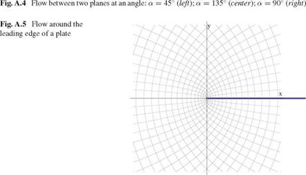
The streamline ф = 0 is given by в = 0 and в = a. The flow between two planes at angle a are shown in Fig. A.4.

Another example is the flow near the sharp leading edge of a flat plate. In this case the complex potential is w(z) = A*fz, see Fig.A.5.
Special Techniques

Notice that at the origin dw/dz is zero for a < n and dw/dz is infinite for a > n. The origin is a singular point in both cases, see Ref. [5].

TO

E0 — En cos t

n=1

h(Z) = 3 Y + 1 u 1 = const, V Z, Z in SW (4.142)

One can now solve for W(Z, Z) as

W(Z, Z) = 3^+1 (uf – U2^ (4.143)

This result also indicates that the data (Cauchy data) on the C – characteristic (Z, Zi) cannot be specified arbitrarily. Substitution in CR+ yields

3-77+1 (u2 – 2U3) = /(Z), V Z, Z in SW (4.144)

which forces one to conclude that U = U(Z) only, hence W = W(Z) as well. As a result, the perturbation velocity и is constant along the C + characteristics, which are straight lines with constant slope /Y+1)u ■

The subdomain SW is called a simple wave region and we can state that in plane supersonic flow, a region adjacent to a uniform flow region is a simple wave region. This result has been extended to the Euler equations in 2-D, see Courant and Friedrichs [8].

[3] 3

^/t+T u (Z)3

[5] CL2D——- bc—— = 2~f

d

[6] 2cd + 2cd 1 Cl,2D

[7] = 2,…, j = 2,…, jx — 1 (8.40)

Backward differences are used for the first derivative of u in x

L = 2pV2S Cl = W

[9]2

Equilibrium of the Glider

The AMAT12 has a rectangular main wing with span bm — 2.1m and constant chord cxm — 0.3 m. The tail is also rectangular with span bt — 1.0 m and chord cxt — 0.338 m. The equilibrium code provides the aircraft aerodynamic characteristics and a maximum take-off mass M — 18 kg. The reference area is Aref — Am + At. The reference length is lref — 2.12 m. The engine is turned off. The global aerodynamic
lift and nose pitching moment coefficients are found to be

CL(a, tt) = 3.853a + 0.902tt + 0.716
См, о(а, tt) = -1.336a – 0.894tt – 0.06

where a represents the geometric incidence and tt the tail setting angle in rd.

15.10.3.1 Equilibrium About the Center of Gravity

The pitching moment about the center of gravity CM, c.g.(a, tt) is given by

Xc

CM, c.g.(a, tt) = См, о (a, tt) + Cl (a, tt)

l-ref

Cm, c.g.(a, tt) = -1.336a – 0.894tt – 0.06 + 0.2868 (3.853a + 0.902tt + 0.716)

Cm, c.g.(a, tt) = -0.2367a – 0.6367tt + 0.1442

The airplane is statically stable since the slope dCm, c.g./da of the moment curve Cm, c.g.(a, tt) is negative.

The aerodynamic center of the glider is at xa. c. = 0.735 m. The static margin SM in %

SM = 100 ( — – —) = 100 (0.3467 – 0.2868) = 6%

lref I ref )

15.10.3.2 Equilibrium Incidence

The equilibrium condition is given by CM, c.g.(aeq, tt) = 0 and can be solved for

aeq(tt)

aeq(tt) = —2.69tt + 0.609

15.10.3.3 Trimming for Maximum Distance

The equilibrium code calculates the tail setting angle for the maximum CL /CD = 9.3 to be tt = 12° = 0.2094 rd.

Substitution of the value of tt in the equilibrium equation gives aeq = -2.69 0.2094 + 0.609 = 0.0457 rd = 2.6°.

The corresponding values of CL and CD, as well as the descent angle в are: Cl = 1.08, Cd = 0.116 and в = – Cd/Cl = -0.107rd = -6.15°.

The lift forces (in N) on the main wing and the tail, given that the velocity is U = 17.3m/s and the air density p = 1.1214 kg/m3 are given by

1 2 1 2
Lm — 2pU AmCLm7 Lt — ^pU AtCLt

The wing and tail lift curves are given respectively by

CLm(a) — 4.664a + 1.312 — 1.525
Cu (a, tt) — 2.342a + 2.583tt – 0.396 — 0.25

The results are: Lm — 161.2 N, Lt — 14.18 N.

Induced Velocity

From the result derived in class

Подпись:TO

Подпись: Ww [y(t)] = -U22nAn

n=1 the distribution of induced velocity reads

wW[y(t)] = —UA1 – sin3^ = —2UA1 – 2cos21

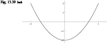
Induced Velocity Подпись: 2l b

= -2UA‘ (‘- 2 (b )’)

The parabolic distribution of ww [y(t)] is shown in Fig. 15.39. The wing experiences upwash for |2y/b| > 1Д/2.

15.10.2.3 Induced Drag

The percent change in induced drag is 33 % increase compared to the elliptic loading. The corresponding efficiency factor is e — 0.75.

Prandtl Lifting Line Theory

15.10.2.1 Lifting Line Theory

The downwash results from the presence of a vortex sheet, downstream of the sharp trailing edge of a finite wing. The sheet is made of line vortices which induce a negative vertical velocity component when the lift is positive, as required from a balance of momentum.

Downwash is associated with induced drag, whereas upwash will produce thrust (negative drag).

There is no net drag benefit to design a wing with upwash. The wing with minimum induced drag for a given lift has elliptic circulation and constant downwash. Any other induced velocity distribution, including with upwash, will produce more induced drag.

15.10.2.2 Design of a Wing

The circulation distribution is represented by the Fourier series

■ Г[y(t)] = 2Ub Z“=1 An sin nt
y(t) = -§ cos t, 0 < t < n

Combining modes 1 and 3 and taking the derivative w. r.t. t yields

Подпись: d Г [y(t)] dt 2Ub (A1 cos t + 3A3 cos 3t) = 0, at t = 0 and n

Подпись:requiring

A1 + 3 A3 = 0

Подпись:

Подпись: 1 Cm, 4 (a) = Cm,o(a) + 4 C1(a) Подпись: 8 dm a a - 2- + - 3в c в в Подпись: 8 d— a 3в ~c - в

Using the identity: cos 3t = cos t 4 cos2 t – 3 one finds d Г [ y (t)]

dt

Prandtl Lifting Line Theory

and the derivative w. r.t. y reads

Подпись: Г {y(t)] Prandtl Lifting Line Theory Подпись: UbA1 sin31 31 Подпись: 8 3 UbA1 Подпись: 3 2
Prandtl Lifting Line Theory

The requirement is satisfied for zero strength tip vortices. With this choice, the circulation distribution becomes

where we used the identity: sin 3t = sin t (4 cos21 — 1). The circulation distribution Г[y(t)] is shown in Fig. 15.38.

2-D Inviscid, Linearized, Thin Airfoil Theories

15.10.1.1 Incompressible Flow (M0 = 0)

Profile Camber Estimation

Thin parabolic plate has only two non-zero Fourier coefficients:

, , . dm

A0 = a, A1 = 4—

c

In thin airfoil theory, the lift coefficient is given by

Q = 2^ A0 + Afj

Solving for A1, given Ci and a reads

( Ci (2.1878

A1 = 2 1 — – ^ = 21 ——————- 0.0698П = 0.5568

1 2ъ ) 6.2832 )

The Fourier coefficients are

A0 = a, A1 = 0.5568, A2 = A3 = ••• = An = 0, n > 2 The relative camber dm/c of the thin parabolic plate is A1/4

= 0.14

c

a 14% relative camber!

Take-Off Incidence

2-D Inviscid, Linearized, Thin Airfoil Theories

For a lift coefficient C; = 2.5, the incidence needed is

Nose Pitching Moment Coefficient

2-D Inviscid, Linearized, Thin Airfoil Theories

In thin airfoil theory, the pitching moment coefficient Cm, o (a) is given by

2-D Inviscid, Linearized, Thin Airfoil Theories

The nose pitching moment coefficient of the wing profile (Cm,0)profile at a = 4° is predicted to be

15.10.1.2 Supersonic Flow (Mq > 1, в = ^

Consider the parabolic plate of equation

2-D Inviscid, Linearized, Thin Airfoil Theoriesx

d (x) = 4dm — c

The slope is given by

Подпись:2-D Inviscid, Linearized, Thin Airfoil Theoriesd

where the relative camber is given to be dm/c = 0.14.

Lift Coefficient

The lift coefficient Ci (a) for all thin airfoils is

a

Ci (a) = 4­P

Drag Coefficient

The equilibrium incidence corresponds to Cm, c (a) = 0, which gives aeq = -0.3733 rd =-21.4°. ’4

The equilibrium is stable, since the moment slope is negative.

Equilibrium Condition and Static Stability

The equilibrium code calculates the linear model for lift and moment coefficients for the complete configuration, at low incidences, to be:

CL(a, tf) = 3.955a + 0.984tf + 0.712
CM, o(a, tf) = -1.188a – 0.907tf – 0.008

The moment coefficient at the center of gravity, CM, c.g.(a, tf) is CMcg (a, tf) = CMo (a, tf) + XcgCL(a, tf) = -0.239a – 0.671tf + 0.163

lref

The condition for equilibrium is that the moment at the center of gravity vanishes

CM, c.g.(aeqj tf ) = 0

The equilibrium is stable because dCM, c.g./da < 0.

Solving for the equilibrium incidence gives

aeq(tf) = —2.808tf + 0.682

15.9.3.3 Take-Off Conditions

The take-off speed of U = 13.11 m/s is obtained for tf = 9.2°. aeq at take-off is aeq = 0.231 rd = 13.2°.

The lift coefficient of the tail at take-off, given that

Cl = 2.696a + 2.705tf – 0.347

is Cu(aeq) = 0.711.

The force on the tail in (N) is Lt = 0.5 pU2AtCLt = 22 N.

The force is up.

15.10 Solution to Problem 10

Equilibrium of the AMAT11

The AMAT11 has a rectangular main wing with span bm = 2.1m and constant chord cxm = 0.3 m. The tail is also rectangular with span bt = 1.0 m and chord cxt = 0.3 m. The equilibrium code provides the aircraft characteristics and a maximum take-off mass M = 19 kg. The reference area is Aref = Am + At.

15.9.3.1 Aspect Ratios of Lifting Elements—Global Lift Slope

The aspect ratio of the wing, ARm and of the tail, ARt are computed as

bm bt

ARm = — = 7.0, ARt = — = 3.33

cxm cxt

Equilibrium of the AMAT11 Equilibrium of the AMAT11

the global lift slope dCL/da for the wing+tail configuration will be

15.9.3.2 Airplane Center of Gravity

The aerodynamic center is located at xa. c./lref = 0.3.

The center of gravity xc. g./lref, given a 6% static margin (SM) will be such that

Xc^ = — – 0.06 = 0.24

lref lref

Prandtl Lifting Line Theory

The WWII Spitfire was designed with an elliptic wing of span b = 11.2m and wing area S = 22.5 m2. It is equipped with a NACA2209.4 profile of 2 % relative camber (d/c = const = 0.02). The top speed in cruise is V = 170 m/s (378 mph) with a take-off mass of M = 3,000 kg.

15.9.2.1 Vortex Sheet

The vortex sheet is a surface of discontinuity for the velocity, that is generated at the sharp trailing edge of a wing, where a Kutta-Joukowski condition holds. In small disturbance theory and for a large aspect ratio wing, one assumes that the vortex sheet is in the base surface generated by straight lines touching the lifting line and parallel to the incoming velocity vector. The rolling-up of the sheet edges is neglected. The u-component of velocity is continuous (< u >= 0) across the vortex sheet, since the pressure is continuous and Cp = —2u/U. The w-component is also continuous (< w >= 0) since the vortex sheet is a stream surface of zero thickness and the fluid is tangent to it (tangency condition imposes w). Only the v-component has a jump (< v > = 0) at the vortex sheet. At a point, this jump is interpreted as the jump due to a vortex filament passing through that point. The vortex sheet is made of vortex filaments that induce a down-wash (or normal wash), responsible for the induced drag. The fundamental effect of the vortex sheet is to produce an inviscid drag, balanced by a propulsive force, whose work adds irreversible kinetic energy to the flow field.

15.9.2.2 Lift Coefficient

By definition, the lift coefficient CL is given by

W 3,000 9.81

Cl = t———- =——- :——— ;—— = 0.075

L 2 pU2 S 0.5 1.2 170222.5

15.9.2.3 Elliptic Loading

The aspect ratio of the wing is AR = b2/S = 5.58. The induced drag CDi is

Подпись:c L

= 0.00032

n AR

Подпись: Ai Подпись: CL n AR Подпись: 0.00428

The first mode amplitude A1 in the Fourier Series expansion is

Подпись: CL (a) Prandtl Lifting Line Theory

The equation for the lift coefficient Cl in terms of aspect ratio AR, geometric incidence a and relative camber d/c reads

In cruise, the incidence a will satisfy the above equation: a = -0.0238 rd = -1.36°

15.9.2.4 Added Twist

Prandtl Lifting Line Theory Prandtl Lifting Line Theory

Adding the third mode only with amplitude A3 = -0.002 increases the induced drag according to

Cot == (Cm)elliptic {1 + 0.655} = 0.00053

The percent change in induced drag is 65.5 %.

The corresponding Efficiency factor e = 1/(1 + 0.655) = 0.604

2-D Inviscid, Linearized, Thin Airfoil Theories

15.9.1.1 Incompressible Flow (M0 = 0)

Aerodynamic Center

The aerodynamic center is the point about which the moment of the aerodynamic forces is independent of the incidence a.

The aerodynamic center is located at the quarter-chord for all thin airfoils at low speeds.

Second Mode only Airfoil

Consider a thin cambered plate such that the vorticity distribution is given by the second mode with A2 > 0 as

Г'[x(t)]=2^{Ao1+nft + A 2 cos2t}
x (t) = 2 (1 – cos t), 0 < t < n

As seen in class

TO

d’[x (t)] = a – A0 + ^ An cos nt = a – A0 + A2 cos 2t

n=1

Integrating in t yields (using d (0) = d (c) = 0)

c

d (c) = (a – A0 + A2cos2t) sin t dt

02

2-D Inviscid, Linearized, Thin Airfoil Theories
Подпись: Aerodynamic Coefficients The lift coefficient is Ci (a) = 2n ^A0 + = 2n(a -

= 2 J (a – A0 + A2(2 cos21 – 1)^ sin t dt

The moment coefficient

C„.0iO = – (A0 + A1 — f) = — (<> – 5^2)

The moment coefficient, at the aerodynamic center, is

7Г 7Г

Cm, a.c. = —4 (A1 — A2) = 4 A2

The drag coefficient is Cd — 0.

Moment About an Axis

The aerodynamic moment about the mid-chord is calculated, using the change of moment formula

1 n A2

Cm, c/2 = Cm, o (a) + 2 Cl(a) = 2 a +————- 6

If the profile is allowed to rotate without friction about an axis located at mid­chord, the equilibrium incidence, aeq, corresponds to Cmc/2 — 0, i. e.

Подпись: A2 ~6

2-D Inviscid, Linearized, Thin Airfoil Theories Подпись: x c

aeq —

No, the equilibrium is unstable because dCmc/2/da — n/2 > 0.

15.9.1.2 Supersonic Flow (M0 > 1, в = yjM^ — 1)

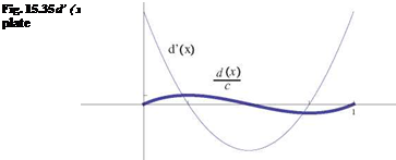
Consider the cubic plate of equation

4 x x x

d (x) = Ac 1 – 2 1 – , A > 0

3 c c c

The slope is given by

,4 x x2

d (x) = A 1 — 6 + 62 3 c c2

This plate equips the fins of a supersonic rocket.

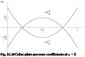
Pressure Distribution and Flow Features

At a = 0 the — C + and — C— are

, 2 , 8 x x2

Подпись: 3в—C + = — d'(x) = — A 1 — 6 + 6 2

— Cp = — d (x) = A 1 — 6 + 6

в

See Fig. 15.36.

Подпись: -Cp Fig. 15.36 Cubic plate pressure coefficients at a = 0

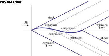
The flow features (shocks, characteristic lines, expansion shocks are shown in Fig. 15.37).

Moment Coefficient

The moment coefficient (Cm,0) 0

, , 4 c. x dx 16 A 1 2

Cm-)a=0 = jl d (x>77 = -3×1 0 – « + K2) – d(

Подпись: = 0

2-D Inviscid, Linearized, Thin Airfoil Theories

16 A -2 3 -4 n1

= – – 2-3 + 3 –

3в 2 2 .

For arbitrary a the moment coefficient reads

aa

Cm, o(a) = (Cm,0)a=0 — 2в = —в

Using the change of moment formula, the mid-chord moment can be evaluated as

1 a 1 a

Cm, c/2 = Cm, o(a) + Cl(a) = — 2 + 4 = 0

2 в 2 в

The moment is independent of a. This is expected, because the mid-chord is the aerodynamic center of thin airfoils in supersonic flow. The value is zero because it is the same as (Cm,0) 0.

There is equilibrium at any value of a. The equilibrium is neutral.

Equilibrium Condition and Static Stability

The moment coefficient at the center of gravity, CM, c.g.(a, tf) is given by the equation CM, c.g.(a) = Cm, o (a) + Cl (a)

lref

Substitution of the linear model yields

CM, c.g.(a) = -1.469a -0.7479tf -0.1565 + 0.268 (4.479a + 0.808tf + 0.9314)

CM, c.g.(a) = -0.2686a – 0.53141/ + 0.0931

The equilibrium is stable since dCM, c.g./da < 0.

The condition for equilibrium is CM, c.g.(aeq) = 0. Solving for aeq gives

aeq (tf) = -1.97841/ + 0.3466

15.8.3.2 Take-Off Conditions

The take-off speed of U = 11.49m/s is obtained for t/ = 7.13° = 0.1244rd. Hence, the incidence at take-off is aeq = 0.1rd = 5.75°.

The tail aerodynamic lift curve is given by

Cli = 3.032a + 2.8861/ – 0.3259

The lift coefficient of the tail at take-off is CLt = 0.336. The force on the tail, given that the tail reference area is At = 0.49 m2, and p = 1.2 kg/m3 will be

1 2

Lt = 2 pU2 AtCLt = 13.0 N The force is up. The tail is lifting.

15.9 Solution to Problem 9