Our heavyweight helicopter equal in the world does not have
In Rostov started production of the most load-lifting rotary-wing car The Russian holding «Helicopt[...]

Everything about aircrafts and helicopters. News and events in aviation worldwide. Civil, transportation, military helicopters and airplanes.

Everything about aircrafts and helicopters. News and events in aviation worldwide. Civil, transportation, military helicopters and airplanes.

Everything about aircrafts and helicopters. News and events in aviation worldwide. Civil, transportation, military helicopters and airplanes.

Everything about aircrafts and helicopters. News and events in aviation worldwide. Civil, transportation, military helicopters and airplanes.


The disadvantages of magnetic balances have so far limited the spread of their use to industrial wind tunnels: the first is the high investment and management costs due to maintenance and to the high consumption of electricity and of cryogenic liquids.
In addition to this economic aspect, the use of magnetic balances can also lead to some technical and operational problems such as:
■ interference from high intensity magnetic fields on control and measurement systems as pressure transducers housed in the model;
■ the risk of damage to both the model and wind tunnel due to the possible loss of control of the model;
■ the difficulty of performing certain experiments as, for example, simulation of propulsion. This type of testing requires the use of gas to be expelled from the model to simulate the presence of a jet. In a conventional wind tunnel, gas is supplied to the model through the support, in a magnetic suspension system, the gas must be contained in tanks housed within the model with space problems;
■ the difficulty of flow visualization (Schlieren, interferometry, etc.) both for the poor optical access to the model and for the possible interference with the optical control systems.
For all these reasons, to date, magnetic balances have been used only in
small wind tunnels, primarily for research purposes.
The number of degrees of freedom of the system depends on both the number and location of the electromagnets and the number of households accommodated within the model. The system in Figure 7.29 can control, for example, only five degrees of freedom (the three shifts and two rotation axes of pitch and yaw) because there is only one core whose magnetization vector is characterized by a single component along the longitudinal axis of the model.
In the case of a model aircraft, the rolling moment is obtained with magnetic cores put in the wings, or building the wings with magnetic material.
 |
Arrangement of position sensors in a five-component balance
Model position detection system can be formed by optical sensors and helium-neon lasers outside the test chamber. The sensors are a combination of linear photodiodes. A typical sensor consists of 1024 photodiodes and has a linear dimension of 1 in., the precision of position detection is therefore about 25 mm. Laser beams, to illuminate the sets of linear photodiodes, are made plane through cylindrical lenses. The position and attitude of the model are obtained by the shadow of the model on the sensors and are measured by the number of illuminated photodiodes. Models are usually painted in matt black in order to avoid possible light reflections.
The number and location of optical sensors and lasers are functions of the number of degrees of freedom to be controlled. Figure 7.29 illustrates the schema of a system of position and attitude sensors in a balance with five degrees of freedom; lacking the sensitivity to roll, only tests on axially symmetric bodies are allowed. The longitudinal position is detected by sensor 2 through the partial shielding of the drag laser beam; the vertical position and the pitch angle from sensors 1 and 5 through the partial shielding of the horizontal laser beams, and finally the transverse position and the yaw angle by sensors 7 and 4 through the partial shielding of the vertical laser beams. Other detection systems may be an X-ray system or a television system.
Electromagnets consist of coils, usually copper, wrapped tightly around a laminated core of ferromagnetic material (soft iron, steel, cobalt). Electromagnets require a refrigeration system, generally water, to dispose of heat produced by the dissipated electricity.
Each plant is characterized by its pattern of electromagnets around the test chamber and by their constructive solutions. The schema of a quite complex plant built at the Southampton University is shown in Figure 7.28: ten magnets, disposed in antagonistic pairs, ensure the
 |
Positions of magnets in a six-component balance at Southampton University, UK
symmetry along the three axes of the wind tunnel, then the system is able to control all degrees of freedom of the model. Magnets 1, 3, 5, 7 control vertical position and pitch angle, magnets 2, 4, 6, 8 control transverse position and yaw angle, while magnets 9 and 10 control the longitudinal position. The roll angle is controlled by the electromagnets from 1 to 8.
The core of the model is usually a permanent magnet made with samarium-cobalt or Alnico. The Alnico provides a greater intensity of
An early one-component magnetic balance made at NASA LARC
|
|
magnetization than samarium-cobalt, but is characterized by a more rapid decrease in the intensity of magnetization and a greater sensitivity to shocks.
An alternative is a core consisting of a solenoid made with a superconducting material (NbTi) wrapped around a core of superconducting material (NIOMAX CN 61/25). Superconducting materials provide virtually zero electrical resistance at extremely low temperatures, in the order of a few degrees K. For this reason, the coil is placed in a cylindrical Dewar vessel containing liquid helium.
Permanent magnets have the advantage of being relatively inexpensive and provide an intensity of magnetization that is practically constant. That means significant simplifications in the calibration procedure of the forces acting on the model as a function of electrical current flowing in the electromagnets. The disadvantage of this type of core is the limited strength of the magnetization vector: this requires, for the same forces and magnetic moments, larger electromagnets and a greater electric power.
The drawbacks of the core made with a superconducting solenoid are:
■ the complexity of building the core and the model;
■ the complexity of the procedure used;
■ operational life of about 70 minutes before the complete evaporation of liquid helium;
■ decline of the current in the solenoid during operation (difficulty in calibration).
In these systems, the model is supported by magnetic forces without any solid support and its aerodynamic interference; the aerodynamic forces are measured through the electrical currents required by the magnetic fields to keep the model in equilibrium with the desired attitude. The first system was built at ONERA in 1957. Since then, many plants have been built in Europe, the United States and Japan.
7.3.5.1Principle of operation
A magnetic support and balance system is composed of five elements:
1. a magnetic core within the model;
2. a set of electromagnets placed outside the test chamber to keep the model in the desired position;
3. an optical system for detecting the position of the model;
4. a system for monitoring the intensity of the electrical current flowing in the electromagnets;
5. an overall management system.
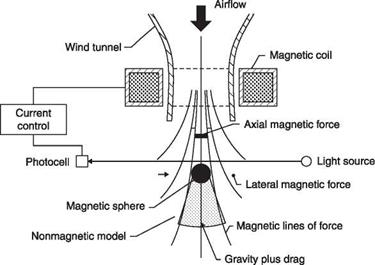
In the plant built at the NASA Langley Research Center (LARC) in 1964, we see in Figure 7.27 a simple example showing the principle of operation of the system. The balance has a single component because the test model is a sphere, the stream is directed downward and hence the direction of the aerodynamic force (drag) coincides with that of gravity.
The system for detecting the position of the model consists of a light beam incident on a photocell. The magnetic field, provided by a magnet coaxial to the wind tunnel, supports the weight of the sphere which intercepts the light beam; the downward displacement of the model due to the aerodynamic force makes the illumination of the photocell vary which results in sending, through its control system, more current in the electromagnet to restore the original position of the model. From the increase in electrical current the intensity of aerodynamic drag can be inferred.
Whichever balance is used, it is essential to carry out a prior calibration applying known forces in the various directions. The easiest way to apply the forces is to use weights and apply them in different directions using appropriate pulleys.
Imperfections in the alignments of the axes of the balance with the stream and interactions of different measured components may occur so that, for example, the application of a force of pure drag may slightly affect the reading of the lift and, generally, of all other components. The procedure to investigate and eliminate the interactions of a complex balance is impressive: the initial set-up of a six-component balance in a large wind tunnel can require months of work.
It is possible to measure the effect on each component of the application of forces along the other axes in turn, find empirical relationships and store them in a computer to use during testing to measure the actual components free from the interactions.
The procedure can be simplified if the interactions are so small that they can be considered linear and hence can be summed. A matrix of coefficients of influence, [C, y], for each applied force, {FA}, on the measured forces, {FM}, can be determined
{FM} = [Cj {Fa}
This matrix can then be inverted to determine, from the readings of the balances, the components of the applied force free from interactions:
{Fa} = [C,;]-1{Fm}
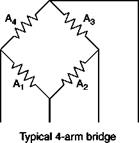
A change in temperature of 1°C produces the same change in resistance produced by a strain numerically equal to a/G, where a is the temperature coefficient of resistance and G is the gage factor. If a = 1/300°C-1, approximate value for many pure metals, the apparent deformation is in the order of 1/600, which would correspond in steel to a stress of approximately 700 Nmm-2, the order of maximum allowable stress; the magnitude of the error can be reduced considerably by using an appropriate material for wire (for the constantan a и 0°C-1). A low temperature coefficient must take precedence over other desirable qualities for the material and is the main reason for the low popularity of semiconductor strain gages in wind tunnel balances.
In addition to the choice of a suitable material, however, other precautions are necessary to minimize errors due to temperature changes. The simplest method of temperature compensation is to provide a second not stretched strain gage near each strain gage and put them in two adjacent sides of a Wheatstone bridge: in this way the temperature changes do not alter the balance of the bridge. The changes in resistance due to temperature are also negated when the responses of two adjacent active strain gages must be subtracted to obtain a force or a moment.
The balances for intermittent wind tunnels and shock tubes can also be thermally insulated. Balances were also used with air conditioning in wind tunnels for continuous operation, particularly those in which large variations in stagnation temperature occur. These precautions should be regarded as additional to the use of a balanced bridge, using a material with a low temperature coefficient of resistance.
The strain gages are also sensitive to moisture in a fairly random way. One reason for not attempting to waterproof each strain gage is the fact that in this case it is more difficult to dry once they are wet, and if problems are expected, the entire balance can be sealed after placing a desiccant inside the enclosure.
7.3.3.2Frequency response
The deformation balances have the advantage of a much faster response: in a null reading balance, even if automatic, the inertia of the system will not allow the measurement of rapidly varying forces. The only limit to the frequency response of a deformation balance is fixed by the natural frequencies of the sting and the model. In addition to the measurement of forces on oscillating models, strain gages can be used to measure the hinge moments of control surfaces: before the introduction of the strain gages hinge moments were measured by connecting the control surface to a balance outside the wind tunnel; the unsteady hinge moments could not be measured by any convenient method.
In resistance strain gages, the elongation caused by the deformation of the element on which they are mounted produces a change in electrical resistance. The relative change in resistance is a multiple (gage factor) of deformation, ranging from two to five in the wire strain gages (see Section 1.4.2). The deformation measured can be related to the force or the bending moment acting on the element. The wire is usually bent zig-zag or spiral to increase the effective length and is embedded in a thin Bakelite support that is glued onto the rod. The typical lengths of strain gages are 0.5 to 1 cm, much larger than those used in structural analysis. Semiconductors have a gage factor of order 100 but are
much more common in pressure transducers than in aerodynamic balances.
7.3.3.1Resolution of forces
The bending moment produced in a sting by the aerodynamic force is proportional to the difference of the readings of two strain gages, assumed to be identical, compressed on one side and elongated on the other side of the sting. The sting is made with a series of hollow sections properly oriented to offer different flexibility depending on the direction of the
![]()
 |
 |
Sting with three-component strain gage balance
components to be measured. In the scheme of Figure 7.25, strain gages are arranged in pairs on the horizontal plates of the frame at the measuring lift and pitching moment. The force and the moment can be calculated from the bending moments, M1 and M2, as computed by the deformation detected by two pairs of strain gages placed at two points at a distance x1 and x2 from the origin of the axes. The force normal to the line joining the two points is given by:
P M – M2 F =-
x1 – x2
and the moment is determined by the equation:
M = M2x1 – M1x2 x1 – x2
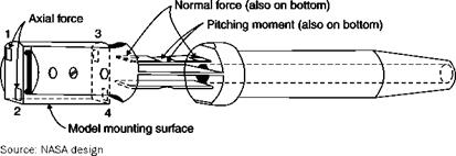
In Figure 7.26, strain gages are arranged on the vertical sides in order to measure drag (axial force) but also normal force contributes to deformations.
The rolling moment can be measured by one or more pairs of strain gages placed at ±45° with respect to the axis of the sting: the torque is
 |
|
Interaction of normal force on axial force
proportional to the differences between strains in these two main directions. Alternatively, the rolling moment can be measured in terms of tension and compression on either side of the central axis of the sting. In the usual procedure the rear of the sting is connected to the tunnel through a buffer that allows the freedom to roll through a braking element to which are attached strain gages.
The strain balances rarely have six components as they are usually designed ad hoc for a particular model. The arrangement of strain gages can be quite complicated even considering the need to compensate for the temperature sensitivity. Since strain gages cannot be considered perfectly equal to each other, an accurate calibration is needed, which can be very challenging with six components.