Category Airplane Stability and Control, Second Edition

Civil Airworthiness Requirements

Military aircraft are procured under comprehensive flying qualities specifications. These specifications are contractual obligations by the manufacturer to a single military customer. On the other hand, the flying qualities of commercial aircraft are generally not governed by contracts with individual customers, but rather by governmental agencies, acting to protect the flying public.

Civil flying qualities requirements are found in airworthiness requirement documents. Compliance with airworthiness standards is proved in flight testing, leading to the award of airworthiness certificates and freedom to market the aircraft. Civil airworthiness require­ments are the minimum set that will ensure safety. This is a different objective than military requirements, which not only address safety, but also the effectiveness of military airplanes in their missions. Thus, flying qualities requirements found in civil airworthiness require­ments are much less detailed than specified requirements for military airplanes. This is a key distinction between the two sets of requirements.

Spoiler Ailerons

Spoiler ailerons project upward from the upper surface of one wing, reducing lift on that wing and thus producing a rolling moment (Figure 5.10). Spoiler ailerons are often the same surfaces used symmetrically to reduce lift and increase drag on large jet airplanes for rapid descents and to assist braking on runways. Spoiler ailerons are generally used either to free wing trailing edges for full-span landing flaps or to minimize wing twist due to aileron action on very flexible wings.

The aerodynamic details of spoiler operation are still not completely understood, even after years of experiment and theoretical studies. The aerodynamics of a rapidly opened spoiler has two phases, the opening and steady-state phases.

Spoiler Ailerons

Figure 5.10 Plug-slot spoiler ailerons used on the Northrop P-61 BlackWidow airplane. An attempt to devote most of the wing’s trailing edge to landing flaps, rather than ailerons. The small guide aileron provides stick force feel. (From Toll, NACA Rept. 868, 1947)

Successful B-52 Compromises

The B-52 Stratofortress appeared in 1951, during the jet’s awkward age. However, the compromises made by Boeing Company engineers to get around the period’s (well – deserved) lack of confidence in flight control hydraulics and electronics were so successful that this airplane continues to have an active service life nearly 50 years later. These com­promises are suited to the B-52’s mission in that required maneuvers are modest and spin recovery is not required.

7.6.1 The B-52 Rudder Has Limited Control Authority

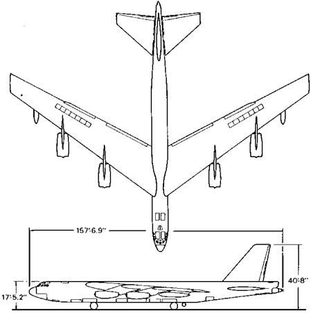
The B-52’s rudder has an exceptionally narrow chord, just 10 percent of the fin chord (Figure 7.4). For a given control surface span or length, control hinge moments are proportional to the chord length squared. This gives the B-52 rudder small operating hinge moments for an airplane of its size, making feasible manual operation through a spring tab. But how about rudder power or effectiveness? How can asymmetric thrust effects and cross-wind takeoffs and landings be made with that exceedingly small rudder?

George S. Schairer explained that the original Boeing design called for an all-moving vertical tail. This was abandoned because of doubts as to the reliability of the hydraulic actuators. Instead, the solution was to incorporate a yaw-adjustable cross-wind landing gear. The yaw-adjustable cross-wind landing gear is preset by the flight crew before takeoff or

Successful B-52 Compromises

Figure 7.4 B-52G Stratofortress. A seventh wing spoiler segment has been added, the feeler ailerons

eliminated. Note the extremely narrow (10-percent chord) rudder and elevators. (From Loftin, NASA SP-468, 1985)

on a landing approach, through a range of 20 degrees to either side of neutral (Figure 7.5). Ground rolls can be made at zero sideslip and bank, the airplane crabbed into the relative wind. The preset landing gear angle is based on the reported wind direction and velocity relative to runway orientation.

Since the airplane has eight engines, asymmetric thrust conditions set up by shutting down an engine are low enough to be handled by the narrow rudder.

10.3.2 Criteria Based on Equivalent Systems

A brief summary of the criteria based on airplane-alone or equivalent system transfer functions is as follows:

10.3.2 Criteria Based on Equivalent Systems

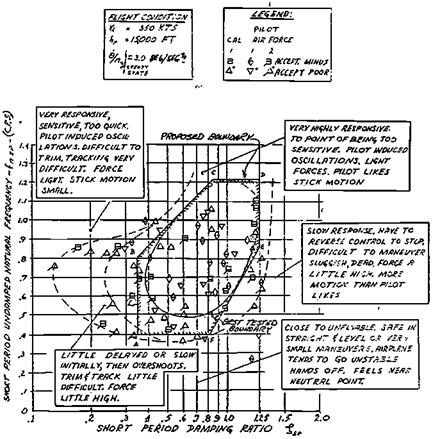
Figure 10.3 Example of an early iso-opinion chart for the longitudinal short-period mode. This one was derived from flight tests of the variable-stability F-94F airplane. (Mazza, Becker, Cohen, and Spector, NADC Report ED-6282, 1963)

Frequency-Damping Boundaries Historically, the earliest findings on pitch sensitivity and sluggishness from variable-stability airplane research was bulls – eye-type pilot opinion contours of the two denominator parameters of the pitch transfer function: natural frequency and damping ratio (Figure 10.3). This work was done by Robert P. Harper and his associates at the Cornell Aeronautical Laboratory in the early 1950s. Gibson (1995) comments that these boundaries ignore the attitude response. He suggests adding quantitative information on attitude response, such as delay, dropback (see subsequent definition), and overshoot.

Numerator Time Constant Requirements The numerator time constant, Tg2, controls the rapidity with which attitude changes result in flight path changes. Shorter values, corresponding to high lift curve slope and light wing loadings, give faster path responses and lower, or better, Cooper-Harper ratings. However, the benefits of low numerator time constants are mainly confined to landing approach control and have little to do with tactical airplane maneuverability.

Bihrle’s Control Anticipation Parameter By far the most successful of the criteria based on pitch transfer function parameters is the control anticipation

10.3.2 Criteria Based on Equivalent Systems

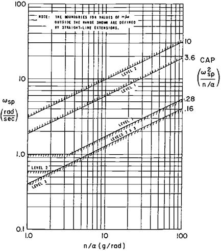
Figure 10.4 MIL-F-8757C short-period mode equivalent natural frequency and CAP (Control

Anticipation Parameter) requirements (1980).

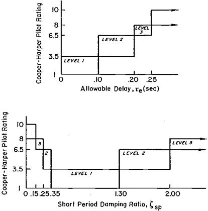
parameter, or CAP (Bihrle, 1966). CAP is the ratio of the airplane’s initial pitch acceleration in an abrupt pullup to the steady-state normal acceleration produced. The initial pitch acceleration lets the pilot anticipate the final acceleration response. It turned out that CAP also could be expressed as the ratio of the pitch natural frequency to a function of the numerator time constant. In that form CAP appears in MIL-F-8785C (Figure 10.4) and is also referenced in the newer MIL-STD-1797. CAP is augmented by requirements on damping ratio and time delay (Figure 10.5).

Gautrey and Cook’s Generic CAP, or GCAP The CAP criterion can be extended to augmented aircraft without recourse to equivalent systems. The generic CAP criterion, or GCAP, uses different parameters than CAP but has the same interpretation. GCAP is neither based on short-period transfer function parameters nor does it require a steady-state normal acceleration, as does CAP. GCAP parameters are well defined even for fully augmented pitch control systems such as are found on the Boeing 777 and Airbus A320-A340 series.

10.3.2 Criteria Based on Equivalent Systems

Figure 10.5 Equivalent systems requirements for longitudinal short-period damping and time delay.

(From MIL-F-8785C, Nov. 1980)

Bandwidth Criterion This is a criterion based on the transfer function for pitch attitude as an output for control force as an input. The pitch attitude band­width is defined arbitrarily as the lower of two frequencies: the gain bandwidth frequency, at which there is a 6-db gain margin, and the phase bandwidth frequency, at which there is a 45-degree phase margin. An additional factor is the phase delay, which accounts for phase lags introduced by higher frequency components, such as control actuators. A typical bandwidth criterion chart is reproduced in Figure 10.6. The bandwidth criterion is considered significant, although the exact shape of suitable boundaries is still a research matter.

Gibson Nichols Chart Criterion This criterion defines satisfactory and unsatis­factory flying qualities regions in the Nichols plane of open-loop transfer func­tion gain and phase. An early version of this criterion is shown in Figure 10.7. The concept of attitude dropback appears on the chart, a term defined subsequently.

The Gossamer and MIT Human-Powered Aircraft

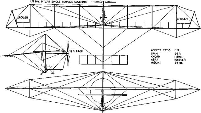
A general arrangement drawing of the original Gossamer Condor human powered airplane is shown in Figure 13.2. All of the Gossamer aircraft are canards because of the packaging convenience of the pilot-powerplant combination with its plastic chain-driven pusher propeller. Like the Wright brothers before them, the team found it relatively easy to control pitch attitude (and angle of attack) even though the center of gravity was behind the neutral point. An opposite wing warp and tilted canard method of roll control developed for the Gossamer Condor (Sec. 5) was applied as well to the Gossamer Albatross. Finally, the Gossamer team pioneered in the art of using carbon fiber plastic tubes as bending and compression members in the airframe structure, thereby ensuring a very light weight (Grosser, 1981).

The MIT human-powered Chrysalis biplane and Monarch and Daedalus monoplanes were less radical in design than the Gossamer series, with tractor propellers and aft tails. All-moving tail surfaces and warping wings for lateral control were used at first. The Daedalus machine dispensed with wing warping or ailerons, relying on rudder control and dihedral effect. This proved insufficient.

The Gossamer and MIT Human-Powered Aircraft

Figure 13.2 Initial version of the Gossamer Condor human-powered ultralight airplane, with single-surface wings and spoilers for lateral control. The airplane could not be turned with the spoilers. (From Burke, “The Gossamer Condor and Albatross,” AIAA Professional Study Series, 1980)

The F-14 Tomcat

The next variable-sweep airplane to see service was the Navy’s Grumman F-14 Tomcat. Static longitudinal stability is excessive with the wings fully swept back at high Mach numbers, even though the F-14 uses the Alford-Polhamus-Wallis arrangement. Grumman corrected the problem with a small leading-edge extension on the glove, which is called a glove vane (Figure 16.2). The vane starts to extend at a Mach number of 1.0, reaching a full 15-degree extension at a Mach number of 1.5.

Other interesting F-14 stability and control features are the use of horizontal tail dif­ferential incidence for lateral control. Wing spoilers also provide lateral control for wing sweep angles below 57 degrees. The spoilers are almost aligned with the wind at sweep angles above 57 degrees, so locking them out loses nothing in roll control power. Like the F-111, the F-14 has triply redundant three-axis stability augmentation. These are analog systems, typical for aircraft of its generation.

16.2 The Rockwell B-1

The Rockwell B-1 strategic bomber is an interesting variable-sweep case in that the aerodynamic center shift when sweeping the wings is large enough to require compensating center of gravity shifts. The wing pivot point is outboard, as in the F-111 and F-14, but the trailing edge of the fully swept wing does not merge with the horizontal tail leading edge. Thus, the B-1 configuration does not take full advantage of destabilizing downwash increases with the wing swept back. The required center of gravity shifting on the B-1 is done by pumping remaining fuel between the forward and aft tanks.

The airplane can be landed if the wing becomes locked in its full aft position of 67.5 degrees (65 degrees for the B-1B), but with full nose-up control minimum airspeed is close to 200 knots, making for a very high-speed landing. The story is that a B-1 based at a U. S. Air Force airfield in Kansas with a wing stuck in its full aft swept position had to fly to Edwards Air Force Base in California to use its extra-long runways.

The B-1 can have a severe stability problem at the other endof the sweep range, the landing position of 15 degrees. This occurs if the wings are swept forward to 15 degrees without waiting for the fuel to be pumped forward as well. This was guarded against originally by a warning light that came on if fuel transfer had not been made before unsweeping. According to Paul H. Anderson, a warning light was used originally instead of a positive interlock that would prevent unsweeping until fuel was transferred because of concern that a failure in the interlock system could lock the wing in its aft position.

However, a tragic accident occurred at Edwards when a pilot apparently ignored the warning light and unswept a B-1’s wings without the compensating forward center of gravity shift by fuel pumping. The airplane simply became uncontrollably unstable and was lost. A positive interlock replaced the warning light after that accident.

Aeroelasticity and Stability and Control

Bernard Etkin (1972) gives a succinct description of the way stability and control engineers handle the effects of airframe distortion or elasticity There are two basic cate­gories into which all treatments fall. Etkin calls these categories “The method of quasistatic deflections” and “The method of normal modes.” Here are his words:

Method of Quasistatic Deflections Many of the important effects of distortion can be accounted for by simply altering the aerodynamic derivatives. The assumption is made that changes in aerodynamic loading take place so slowly that the structure is at all times in static equilibrium. (This is equivalent to assuming that the natural frequencies of vibration of the structure are much higher than the frequencies of the rigid-body motions.) Thus a change in load produces a proportional change in the shape of the vehicle, which in turn influences the load.

Method of Normal Modes When the separation in frequency between the elastic degrees of freedom and the rigid-body motions is not large, then significant inertial coupling can occur between the two. In that case, a dynamic analysis is required, which takes account of the time dependence of the elastic motions.

In the latter case Etkin goes on to describe the application of normal mode analysis to the stability and control problem. The important distinction between the quasistatic and normal mode treatments holds as well for the approximate normal modes generated by quasi-rigid models.

19.1 Wing Torsional Divergence

Wing torsional divergence, in which the wing structure itself becomes unstable, tip incidence increasing without limit, is a structural rather than stability and control problem. Torsional divergence occurs with increasing airspeed if the wing’s aerodynamic center is ahead of its shear center, or elastic axis. Although wing torsional divergence is not strictly a stability and control problem, it is the first known phenomenon that can be analyzed with methods used in aeroelastic stability and control.

According to Bisplinghoff, Ashley, and Halfman (1955), the wing failure that wrecked Samuel P. Langley’s Aerodrome on the Potomac River in 1903 was a wing torsional di­vergence. While there has been some controversy on this point, a torsional divergence occurrence that appears quite certain was on the Fokker D-8 monoplane in 1917. When the first D-8 was sandbag-loaded the wing was proved to be sufficiently strong, but the German government’s engineering division called for rear spar strength equal to that of the front spar. The change was made and three D-8 airplanes, one after the other, were lost when their wings failed in flight. The story is picked up in Anthony H. G. Fokker’s book Flying Dutchman:

I took a new wing out of production and treated it to a sandload test in our own factory. As it was progressively loaded, the deflections of the wing were carefully measured from tip to tip. I discovered that with the increasing load, the angle of incidence at the wing tips increased perceptibly. I did not remember having observed this action in the case of the original wings, as first designed by me. It suddenly dawned on me that this increasing angle of incidence was the cause of the wing’s collapse, as logically the load resulting from pressure in a steep dive would increase faster at the wing tips than in the middle, owing to the increased angle of incidence.

This is a classic wing torsional divergence, since the increasing wing tip incidence increased tip aerodynamic load, which further increased the incidence, and so on. The problem was solved when the government permitted the front spar to be reinforced to bring back the original ratio of stiffness between the front and rear spars. This moved the shear center forward.

The Wright brothers and a few other aviation pioneers used the wing’s elastic properties in a positive sense, warping them for lateral control. The Wrights had no problems with aeroelasticity, aside from an unimportant loss in propeller thrust due to blade twisting.

Time Domain and Linear Quadratic Optimization

Control system synthesis in the time domain, rather than in the frequency domain, is often called modern control theory. Optimal controller design is generally involved.

Although one usually thinks of modern control theory in connection with full automatic control, it is applied as well to the design of stability-augmentation systems.

Linear quadratic (LQ) optimization methods have been used for a number of stability- augmentation system designs. These methods have their origins in the work of R. E. Kalman. Airframe and controller equations are cast in the state matrix form discussed in the previous chapter. The optimal controller is a linear feedback law that minimizes an integral cost function J of the form

Подпись:J [x T Qx + 8T R8]dt,

where x is the system state vector, 8 is the control vector, and Q and R are weighting matrices that express the designer’s ideas on what constitutes optimal behavior for this case. The optimal control law takes the form of a linear set of feedback gains 8 = Cx, where C is the gain matrix of constants. The gain matrix C is computed by a matrix equation called the Riccati equation.

The linear quadratic approach to controller design is attractive because it is an organized method for finding feedback gains. The method produces an optimal set of feedbacks, but only for the arbitrarily chosen weighting matrix values. One can argue that if the weighting matrix values are poorly chosen, the resulting system can be far from ideal. In fact, it is not uncommon for designers using linear quadratic methods to tinker with weighting matrix values until a reasonable-looking system emerges. This puts the optimal design method on all fours with ordinary cut-and-try methods.

The problem of assigning weighting matrix values aside, there have been numerous vari­ants of the linear quadratic approach to controller design and any number of applications in the literature and in practice. A typical application is to the design of a lateral-directional command augmentation system (Atzhorn and Stengel, 1984). The criterion function in­cludes control system rate as a means of limiting high-frequency or rapid control motions. Displacement and rate saturation are significant nonlinearities that cannot be treated with the linear quadratic approach, except by the use of describing functions (Hanson and Stengel, 1984). Other linear quadratic stability-augmentation designs that may be found in the litera­ture include departure-resistant controls, superaugmented (unstable airplane) pitch controls, and multiloop roll-yaw augmentation.

According to Robert Clarke and his associates at the NASA Dryden Flight Research Center, the Grumman X-29A research airplane’s flight controls were originally designed using an optimal model-following technique. Simplified computer, actuator, and sensor models were used in the original analysis, leading to an unconservative design. A classical approach was chosen in the end, with lags introduced by the actual hardware compensated for by the addition of lead-lag filters (Clarke, Burken, Bosworth, and Bauer, 1994).

Another interesting linear quadratic stability augmentation design adds feed-forward compensation for nonlinear terms that cannot be included in the linearized design. This is the stability-augmentation system for the Rockwell/Deutsche Aerospace X-31 research airplane. Feed-forward compensation is added for nonlinear engine gyroscopic and inertial coupling effects (Beh and Hofinger, 1994).

Airplane Stability and Control, Second Edition

From the first machines that flew for just minutes at a time to today’s sophisticated aircraft, stability and control have always been crucial considerations. Following up their successful first edition, Malcolm Abzug and Eugene Larrabee forge through to the present day with their informal history of the personalities and the events, the art and the science of airplane stability and control.

The authors, widely known for their contributions to airplane design and de­velopment, have captured both the technological progress and the excitement of this important facet of aviation. Much of the book’s content captures never-before- available impressions of those active in the field, from pre-Wright brothers air­plane and glider builders straight through to contemporary aircraft designers. The chapters are arranged thematically, dealing with single subjects over their entire history. These include early developments, research centers, the effects of power on stability and control, the discovery of inertial coupling, the challenge of stealth aerodynamics, a look toward the future, and much more. This updated edition includes new developments in propulsion-controlled aircraft, fly-by-wire technol­ogy, redundancy management, applications, and safety. It is profusely illustrated with photographs and figures and includes brief biographies of noted stability and control figures along with a core bibliography. Professionals, students, and aviation enthusiasts alike will appreciate the comprehensive yet readable approach to this history of airplane stability and control.

Malcolm J. Abzug is the former president of ACA Systems.

E. Eugene Larrabee is Professor Emeritus at the Massachusetts Institute of Technology.

Airplane Stability and Control, Second Edition

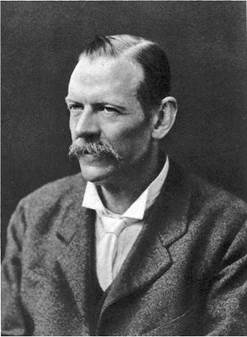
Frontispiece George Hartley Bryan (1864-1928). The originator, withW. E. Williams, ofthe equationsofairplane motion. Bryan’s equations are the basis for the analysis of airplane flight dynamics and closed-loop control and forthe design of flight simulators. (From Obit. Notices ofFellows of the Royal Soc., 1932-1935)

Long-Lived Stability and Control Myths

The achievements of S. B. Gates, R. R. Gilruth, and others in putting airplane stability and control on a scientific basis have not eliminated a number of early myths attached to the subject. Dr. John C. Gibson (1995) lists no fewer than 15 of these myths and counters them with what we know to be correct. A few of the Gibson’s list of 15 myths and corrections follow:

Wing center of pressure (cp) movement affects longitudinal stability. Correction: Wing cp movement with angle of attack is controlled by the wing’s zero-lift pitching moment coefficient about itsaerodynamic center(1/4 chord), or Cm0. Thisparameteraffectsonly trim for rigid airplanes. Wing cp has been discarded in modern stability and control calculations and replaced by wing aerodynamic center and Cm 0.

A down tail load is required for stability. Correction: Stability is provided by the change in tail load with change in airplane angle of attack. The change is independent of the direction of the initial load.

Gibson comments that this myth survives in FA A private pilot examinations and in an exhibit at the National Air and Space Museum in Washington. This subject is distinct from the instability caused by tail down load in the presence of propeller slipstream, an effect discussed in Chapter 4, Section 6.

A stable airplane is less maneuverable than an unstable one. Correction: Unstable airplanes are notoriously difficult to control precisely. Given light control forces, a sta­ble airplane can be pitched rapidly to a precise load factor or aiming point. Gibson says, “… the [stable] Hurricane, Typhoon, and Tempest were highly manoeuvrable and were greatly superior as gun platforms to the skittish Spitfire.”

The reader is referred to Gibson’s 1995 paper for the rest of these interesting myths and their corrections.

CHAPTER 4