The hovercraft
In conventional winged aircraft lift, associated with circulation round the wings, is used to balance the weight, for helicopters the ‘wings’ rotate but the lift generation is the same. A radically different principle is used for sustaining of the hovercraft. In machines of this type, a more or less static region of air, at slightly more than atmospheric pressure, is formed and maintained below the craft. The difference between the pressure of the air on the lower side and the atmospheric pressure on the upper side produces a force tending to lift the craft. The trapped mass of air under the craft is formed by the effect of an annular jet of air, directed inwards and downwards from near the periphery of the underside. The downwards ejection of the annular jet produces an upwards reaction on the craft, tending to lift it. In steady hovering, the weight is balanced by the jet thrust and the force due to the cushion of air below the craft. The difference between the flight of hovercraft and normal jet-lift machines lies in the air cushion effect which amplifies the vertical force available, permitting the direct jet thrust to be only a small fraction of the weight of the craft. The cushion effect requires that the hovering height/diameter ratio of the craft be small, e. g. 1/50, and this imposes a severe limitation on the altitude attainable by the hovercraft.
Consider the simplified system of Fig. 9.10, showing a hovercraft with a circular planform of radius r, hovering a height h above a flat, rigid horizontal surface. An annular jet of radius r, thickness t, velocity V and density p is ejected at an angle в to the horizontal surface. The jet is directed inwards but, in a steady, equilibrium state, must turn to flow outwards as shown. If it did not, there would be a continuous increase of mass within the region C, which is impossible. Note that such an increase of mass will occur for a short time immediately after starting, while the air cushion is being built up. The curvature of the path of the air jet shows that it possesses a centripetal acceleration and this
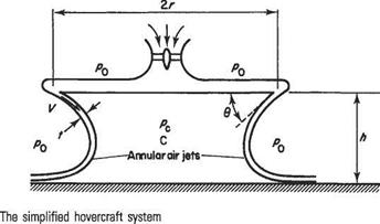
is produced by a difference between the pressure pc within the air cushion and the atmospheric pressure pq. Consider a short peripheral length 6s of the annular jet and assume:
(i) that the pressure pc is constant over the depth h of the air cushion
(ii) that the speed V of the annular jet is unchanged throughout the motion.
Then the rate of mass flow within the element of peripheral length 6s is pVt fa kgs-1. This mass has an initial momentum parallel to the rigid surface (or ground) of pVt6sVcos 0 = pV^t cos 0 6s inwards.
After turning to flow radially outwards, the air has a momentum parallel to the ground of pVt6sV = pV2t 6s outwards. Therefore there is a rate of change of momentum parallel to the ground of pV2t( + cos 0) 6s. This rate of change of momentum is due to the pressure difference (pc — po) and must, indeed, be equal to the force exerted on the jet by this pressure difference, parallel to the ground, which is (pc — po)h 6s. Thus
(Pc — po)h6s = pV2t(l + cos0) 6s
or
(Pc~Po)=^Y^( 1 + COS0) (9.73)
Thus the lift Lc due to the cushion of air on a circular body of radius r is
7i■or2V2t
Lc = nr2(pc – po) =—- —— (l+cos0) (9.74)
n
The direct lift due to the downwards ejection of the jet is
Lj = pVt 2-кг F sin 0 = Іттгр V2t sin 0 (9.75)
and thus the total lift is
|
L = 7rrpF2* |2sin0 4- |
(l+cos0)} (9.76)
If the craft were remote from any horizontal surface such as the ground or sea, so that the air cushion has negligible effect, the lift would be due only to the direct jet
thrust, with the maximum value L-ia — 2nrpV2t when # = 90°. Thus the lift amplification factor, L/Lj0, is
Differentiation with respect to # shows that this has a maximum value when
![]() „ 2 h tan# = —
„ 2 h tan# = —
Since machines of this type are intended to operate under conditions such that h is very small compared to r, it follows that the maximum amplification is achieved when # is close to zero, i. e. the jet is directed radially inwards. Then with the approximations sin # = 0, cos # = 1:
![]() L__h
L__h
r
and
It will be noted that the direct jet lift is now, in fact, negligible.
The power supplied is equal to the kinetic energy contained in the jet per unit time[78] which is
![]() і 2nr pVt V2 = 7гг p V3t
і 2nr pVt V2 = 7гг p V3t
Denoting this by P, combining Eqns (9.80) and (9.81), and setting lift L equal to the weight W, leads to
P__Vh W~ 2r
as the minimum power necessary for sustentation, while, if в Ф 0,
P _ Vh W r(l + cos#)
ignoring a term involving sin#. Thus if Vis small, and if h is small compared to r, it becomes possible to lift the craft with a comparatively small power.
The foregoing analysis applies to hovering flight and has, in addition, involved a number of simplifying assumptions. The first is the assumption of a level, rigid surface below the machine. This is reasonably accurate for operation over land but is not justified over water, when a depression will be formed in the water below the craft. It must be remembered that the weight of the craft will be reacted by a pressure distributed over the surface below the machine, and this will lead to deformation of a non-rigid surface.
Another assumption is that the pressure pc is constant throughout the air cushion. In fact, mixing between the annular jet and the air cushion will produce eddies leading to non-uniformity of the pressure within the cushion. The mixing referred to above, together with friction between the air jet and the ground (or water) will lead to a loss of kinetic energy and speed of the air jet, whereas it was assumed that the speed of the jet remained constant throughout the motion. These effects produce only small corrections to the results of the analysis above.
If the power available is greater than is necessary to sustain the craft at the selected height h, the excess may be used either to raise the machine to a greater height, or to propel the craft forwards.
Exercises
1 If an aircraft of wing area S and drag coefficient Сд is flying at a speed of V in air of density p and if its single airscrew, of disc area A, produces a thrust equal to the aircraft drag, show that the speed in the slipstream Vs, is, on the basis of Froude’s momentum theory
y.= y{i+lcD
2 A cooling fan is required to produce a stream of air, 0.5 m in diameter, with a speed of 3 m s-1 when operating in a region of otherwise stationary air of standard density. Assuming the stream of air to be the fully developed slipstream behind an ideal actuator disc, and ignoring mixing between the jet and the surrounding air, estimate the fan diameter and the power input required. (Answer: 0.707 m diameter; 3.24 W)
3 Repeat Example 9.2 in the text for the case where the two airscrews absorb equal powers, and finding (i) the thrust of the second airscrew as a percentage of the thrust of the first, (ii) the efficiency of the second and (iii) the efficiency of the combination.
(Answer: 84%; 75.5%; 82.75%)
4 Calculate the flight speed at which the airscrew of Example 9.3 of the text will produce a thrust of 7500 N, and the power absorbed, at the same rotational speed.
(Answer 93 ms-1; 840 kW)
5 At 1.5 m radius, the thrust and torque gradings on each blade of a 3-bladed airscrew revolving at 1200 rpm at a flight speed of 90 m s-1 TAS at an altitude where er = 0.725 are 300 Nm-1 and 1800 N mm-‘respectively. If the blade angle is 28°, find the blade section absolute incidence. Ignore compressibility. (Answer. 1°48’) (CU)
6 At 1.25 m radius on a 3-bladed airscrew, the aerofoil section has the following characteristics:
solidity = 0.1; 0 = 29°7′; a = 4°7′; CL = 0.49; L/D = 50
Allowing for both axial and rotational interference find the local efficiency of the element. (Answer: 0.885) (CU)
7 The thrust and torque gradings at 1.22 m radius on each blade of a 2-bladed airscrew are 2120Nm-1 and 778 Nmm-1 respectively. Find the speed of rotation (in rads-1) of the airstream immediately behind the disc at 1.22m radius.
(Answer: 735rads-1)
8 A 4-bladed airscrew is required to propel an aircraft at 125ms-1 at sea level, the rotational speed being 1200 rpm. The blade element at 1.25 m radius has an absolute incidence of 6° and the thrust grading is 2800 Nm’1 per blade. Assuming a reasonable value for the sectional lift curve slope, calculate the blade chord at 1.25 m radius. Neglect rotational interference, sectional drag and compressibility.
(Answer. 240 mm)
9 A 3-bladed airscrew is driven at 1560 rpm at a flight speed of 110 m s-1 at sea level. At 1.25 m radius the local efficiency is estimated to be 87%, while the lift/drag ratio of the blade section is 57.3. Calculate the local thrust grading, ignoring rotational interference.
(.Answer: 9000 Nm-1 per blade)
10 Using simple momentum theory develop an expression for the thrust of a pro
peller in terms of its disc area, the air density and the axial velocities of the air a long way ahead, and in the plane, of the propeller disc. A helicopter has an engine developing 600kW and a rotor of 16m diameter with a disc loading of 170Nm-2. When ascending vertically with constant speed at low altitude, the product of the lift and the axial velocity of die air through the rotor disc is 53% of the power available. Estimate the velocity of ascent. (.Answer. 110 m min-1) (U of L)

[1] Quite often ‘dimension’ appears in the form ‘a dimension of 8 metres’ and thus means a specified length. This meaning of the word is thus closely related to the engineer’s ‘unit’, and implies linear extension only. Another common example of its use is in ‘three-dimensional geometry’, implying three linear extensions in different directions. References in later chapters to two-dimensional flow, for example, illustrate this. The meaning above must not be confused with either of these uses.
* Some authorities express temperature in terms of length and time. This introduces complications that are briefly considered in Section 1.2.8.
[2] Since many valuable texts and papers exist using those units, this book contains, as Appendix 4, a table ot factors Гог converting from the Imperial system to the SI system.
[3] For example, the Aeronautical Research Committee Current Paper No. 369 which was also published in the Journal of the Royal Aeronautical Society, November 1958.
[4] Recent reviews are given by M. Gad-el-Hak (1999) The fluid mechanics of microdevices – The Freeman Scholar Lecture. J. Fluids Engineering, 121, 5—33; L. Lofdahl and M. Gad-el-Hak (1999) MEMS applications in turbulence and flow control. Prog, in Aerospace Sciences, 35, 101-203.
[5] It should be noted that in a general system the fluid would also do work which should be taken into the equation, but it is disregarded here for the particular case of flow in a stream tube.
[6] In fact, this statement is somewhat of an over-simplification. Technically the turbulence characteristics of the oncoming flow also influence the details of the flow field.
[7] Continuity equation for two-dimensional flow in polar coordinates (a) Consider a two-dimensional flow field expressed in terms of the cylindrical coordinate system (г, ф, z) where all flow variables are independent of the azimuthal angle ф. For example, the flow over a circular cylinder. If the velocity components (и, v) correspond to the coordinate directions (г, ф) respectively, show that the continuity equation is given by
[8] Here ro is the radius of the equipotcntial ф = 0 for the isolated source and the isolated sink, but not for the combination.
[9] J. L. Hess and A. M.O. Smith ‘Calculation of Potential Flow about Arbitrary Bodies’ Prog, in Aero. Set, 8 (1967).
[10] W. H. Press etal. (1992) Numerical Recipes. The Art of Scientific Computing. 2nd ed. Cambridge University Press.
[11]W. Kutta (1902) ‘Lift forces in flowing fluids’ (in German), III. Aeronaut. Mitt., 6, 133.
[12] see footnote on page 161.
j N. Zhukovsky ‘On the shape of the lifting surfaces of kites’ (in German), Z. Flugtech. Motorluftschiffahrt, 1, 281 (1910) and 3, 81 (1912).
[13] Z. Flugtech. Motorluftschiffahrt, 9, 111 (1918). f NACA Report, No. 411 (1931).
[14] N. D. Halsey (1979) Potential flow analysis of multi-element airfoils using conformal mapping, AIAA J., 12, 1281.
*NACA Report, No. 142 (1922).
8 Aeronautical Research Council, Reports and Memoranda No. 910 (1924).
[15]
[16] See R and M, No. 1095, for the complete analysis.
* D. A. Spence, The lift coefficient of a thin, jet flapped wing, Proc. Roy. Soc. A., No. 1212, Dec. 1956. D. A. Spence, The lift of a thin aerofoil with jet augmented flap, Aeronautical Quarterly, Aug. 1958.
[17] II is suggested that this section be omitted from general study until the reader is familiar with these derivatives and their use.
[18]Lighthill, M. J. (1951) ‘A new approach to thin aerofoil theory’, Aero. Quart., 3, 193. ^ J. Weber (1953) Aeronautical Research Council, Reports & Memoranda No. 2918.
[19] P. E. Rubbert (1964) Theoretical Characteristics of Arbitrary Wings by a Nonplanar Vortex Lattice Method D6-9244, The Boeing Co.
[20] J. L. Hess (1972) Calculation of Potential Flow about Arbitrary Three-Dimensional Lifting Bodies Douglas Aircraft Co. Rep. MDC J5679/01.
*A full description is given in J. D. Anderson (1985) Fundamentals of Aerodynamics McGraw-Hill.
[21] see Bibliography.
* Prandtl, L. (1918), Tragfliigellheorie, Nachr. Ges. Wiss., Gottingen, 107 and 451.
[22] There is no fully convincing physical explanation for the production of the starting vortex and the generation of the circulation around the aerofoil. Various incomplete explanations will be found in the references quoted in the bibliography. The most usual explanation is based on the large viscous forces associated with the high velocities round the trailing edge, from which it is inferred that circulation cannot be generated, and aerodynamic lift produced, in an inviscid fluid. It may be, however, that local flow acceleration is equally important and that this is sufficiently high to account for the failure of the flow to follow round the sharp trailing edge, without invoking viscosity. Certainly it is now known, from the work of T. Weis-Fogh [Quick estimates of flight fitness in hovering animals, including novel mechanisms for lift production, J. Expl. Biol., 59, 169-230, 1973] and M. J. Lighthill [On the Weis-Fogh mechanism of lift generation, J. Fluid Mech., 60,1-17,1973] on the hovering flight of the small wasp Encarsia formosa, that it is possible to generate circulation and lift in the complete absence of viscosity.
In practical aeronautics, fluid is not inviscid and the complete explanation of this phenomenon must take account of viscosity and the consequent growth of the boundary layer as well as high local velocities as the motion is generated.
[23] Saffman, P. G. 1992 Vortex Dynamics, Cambridge University Press.
[24] The leader is flying in a flow regime that has additional vertical flow com
ponents induced by the following vortices. Upward components appear from the bound vortices агсг, азСз, trailing vortices C2d2, азЬз and downward
[26]L. Deighton (1977) Fighter Jonathan Cape Ltd.
[27] Pohlhamus, E. C. (1966), ‘A Concept of the Vortex Lift of Sharp-Edge Delta Wings Based on a Leading – Edge-Suction Analogy’, NASA TN D-3767; See also ‘Applying Slender Wing Benefits to Military Aircraft’, AIAA J. Aircraft, 21, 545-559, 1984.
[28] See B. Hunt (1978) ‘The panel method for subsonic aerodynamic flows: A survey of mathematical formulations and numerical models and an outline of the new British Aerospace scheme’, in Computational Fluid Dynamics, ed. by W. Kollmann, Hemisphere Pub. Corp., 100-165; and a review by J. L. Hess (1990) ‘Panel methods in computational fluid dynamics’, Ann. Rev. Fluid Mech, 22, 255-274.
[29] D. N. Holder el at., ARCR and M, 2782, 1953.
[30] Th. Meyer, Ober zweidimensionale Bewegungsvorgange in einem Gas das mit Oberschallgeschwindigkeit strdmt, 1908.
t See, for example, E. L. Houghton and A. E. Brock, Tables for the Compressible Flow of Dry Air, 3rd Edn, Edward Arnold, 1975.
[31] J. Ackeret, Z. Flugtech Motorluftschiff, pp. 72-4, 1925. Trans. D. M. Milner in NAC & TM, 317.
T From suitable tables, e. g. E. L. Houghton and A. E. Brock, Tables for the Compressible Flow of Dry Air, 3rd Edn, Edward Arnold, 1975.
[32] A. Feni, Experimental results with aerofoils tested in the high-speed tunnel at Guidomia, Atti Guidornia, No. 17, September 1939.
[33] e. g. E. L. Houghton and A. E. Brock, Tables for the Compressible Flow of Dry Air, 3rd Edn., Edward. Arnold, 1975.
[34] A. Jameson, ‘Full-Potential, Euler and Navier-Stokes Schemes’, in Applied Computational Aerodynamics, Vol. 125 of Prog, in Astronautics and Aeronautics (ed. By P. A. Henne), 39-88 (1990), AIAA: New York.
[35] This chapter is concerned mainly with incompressible flows. However, the general arguments developed are also applicable to compressible flows.
[36]P. R. Owen and L. Klanl’er, RAE Reports Aero., 2508, 1953.
* Reynolds number here is defined as V^Djw where Vx is the free stream velocity, v is the kinematic viscosity in the free stream and D is the cylinder diameter.
1.8 x 10⁻⁵
[38] W. Tollmien (1929) Uber die Entstehung der Turbulenz. I. Mill. Nachr. Ges. Wiss. Gottingen, Math. Phy. s. Klas. se. pp. 21-44.
f H. Schlichling (1933) Zur Entstehung der Turbulenz bei der Plattenstromung. Z. angew. Math. Mech.. 13, 171-174.
[39]G. B. Schubauer and H. K. Skramstadt (1948) Laminar boundary layer oscillations and transition on a flat plate. NACA Rep., 909.
[40] J. Boussinesq (1872) Essai sur la theorie des eaux courantes. Memoires Acad, des Science, Vol. 23, No. 1, Paris.
* L. Prandtl (1942) Bemerkungen zur Theorie der freien Turbulenz, ZAMM, 22, 241-243.
1 H. Reichardt (1942) Gesetzmassigkeiten der freien Turbulenz, VDI-Forschmgsheft, 414, 1st Ed., Berlin.
[41] L. Prandtl (1925) Bericht fiber Untersuchunger zur ausgebildeten Turbulenz, ZAMM, 5, 136-139.
[42]Th. von Karman (1930) Mechanische Ahnlichkeit und Turbulenz, Nachrichten der Akademie der Wissenschaften Gd’ttingen, Math.-Phys. Klasse, p. 58.
tG. I. Barenblatt and V. M. Prostokishin (1993) Scaling laws for fully-developed turbulent shear flows, J. Fluid Mech., 248, 513-529.
[43] P. W. Carpenter (1997) The right sort of roughness, Nature, 388, 713-714.
[44] S. J. Kline, W. J. Reynolds, F. A. Schraub and P. W. Runstadler (1967) The structure of turbulent boundary layers, J. Fluid Mech., 30, 741-773.
[45]K. Narahari Rao, R. Narasimha and M. A. Badri Narayanan (1971) The ‘bursting’ phenomenon in a turbulent boundary layer, J. Fluid Mech., 48, 339.
1 Blackwelder, R. F. and Haritonidis, J. H. (1983) Scaling of the bursting frequency in turbulent boundary layers, J. Fluid Mech., 132. 87-103.
* R. L. Panton (ed.) (1997) Self-Sustaining Mechanisms of Wall Turbulence. Computational Mechanics Publications, Southampton.
[46] For a general description of MEMS technology see Maluf, N. (2000) An Introduction to Microelectromechanical Systems Engineering. Artech House; Boston/London. And for a description of their potential use for flow control see Gad-el-Hak, M. (2000) Flow Control. Passive. Active, and Reactive Flow Management, Cambridge University Press.
*The concept of the synthetic jet was introduced by Smith, B. L. and Glezer, A. (1998) The formation and evolution of synthetic jets, Phys. Fluids, 10, 2281-2297. For its use for flow control, see: Crook, A., Sadri. A. M. and Wood, N. J. (1999) The development and implementation of synthetic jets for the control of separated flow, AIAA Paper 99-3176′, and Amitay, M. elal. (2001) Aerodynamics flow control over an unconventional airfoil using synthetic jet actuators, AIAA Journal. 39, 361-370. A study of the use of these actuators for boundary-layer control based on numerical simulation is described by Lockerby. D. A., Carpenter, P. W. and Davies, C. (2002) Numerical simulation of the interaction of MEMS actuators and boundary layers, AIAA Journal, 39, 67-73.
[47] B. Thwaites (1949) ‘Approximate calculation of the laminar boundary layer’, Aero. Quart., 1, 245.
1 M. R. Head (1958) ‘Entrainment in the turbulent boundary layers’, Aero. Res. Council, Rep. & Mem., 3152.
[48] See N. A. Jaffe, T. T. Okamura and A. M.O. Smith (1970) ‘Determination of spatial amplification factors and their application to predicting transition’, AIAA J., 8, 301-308.
f A. R. Wazzan, C. Gazley and A. M.O. Smith (1981) ‘H-Rx method for predicting transition’, AIAA J., 19, 810-812.
[49] For example, see Fersiger, J. H. (1998) Numerical Methods for Engineering Application, 2nd Ed., Wiley; Fersiger, J. H. and Peric, M. (1999) Computational Methods for Fluid Dynamics, 2nd Ed., Springer; Schli – chting, H. and Gersten, K. (2000) Boundary Layer Theory, Chap. 23, 8th Ed., McGraw-Hill.
TA guide on how to use commercial CFD is given by Shaw, C. T. (1992) Using Computational Fluid Mechanics, Prentice Hall.
[50] Keller, H. B. (1978) Numerical methods in boundary-layer theory, Annual Review FluidMech., 10,417-433.
[51] Spalart, P. R. and Watmuff, J. H. (1993) Direct simulation of a turbulent boundary layer up to Re = 1410, J. Fluid Mech., 249, 337-371; Moin, P. and Mahesh, K. (1998) Direct numerical simulation: A tool in turbulence research, Annual Review Fluid Mech., 30, 539-578; Friedrich, R. etal. (2001) Direct numerical simulation of incompressible turbulent flows, Computers & Fluids, 30, 555-579.
1 Agarwal, R. (1999) Computational fluid dynamics of whole-body aircraft, Annual Review Fluid Mech., 31, 125-170.
[52]Cebeci, T. and Smith, A. M.O. (1974) Analysis of Turbulent Boundary Layers, Academic Press.
^ Van Driest, E. R. (1956) On the turbulent flow near a wall, J. Aeronautical Sciences, 23, 1007-1011.
1 Clauser, F. H. (1956) The turbulent boundary layer, Adv. in Applied Mech., 4, 1-51.
5Corrsin, S. and Kistler, A. L. (1954) The free-stream boundaries of turbulent flows, NACA Tech. Note 3133. KlebannoiT, P. S. (1954) Characteristics of influence in a boundary layer with zero pressure gradient, NACA Tech. Note 3178 and NACA Rep.1247.
[53] Smagorinsky, J. (1963) General circulation experiments with the primitive equations: 1. The basic equations, Mon. Weather Rev., 91, 99-164.
1 Tucker, P. G. (2001) Computation of Unsteady Internal Flows. Kluwer Academic Publishers, Norwell, MA, U. S.A.
[54] A. M.O. Smith (1975) ‘High-Lift Aerodynamics’, J. Aircraft, 12, 501-530. Many of the topics discussed in Sections 8.1 and 8.2 are covered in greater depth by Smith.
[55]B. S. Stratford (1959) The prediction of separation of the turbulent boundary layer. J. Fluid Mech., 5, 1-16.
[56] R. H. Liebeck (1973) A class of aerofoils designed for high, lift in incompressible flow. J. of Aircraft, 10, 610-617.
fP. B.S. Lissaman (1983) ‘Low-Reynolds-number airfoils’, Annual Review of Fluid Mechanics, 15,223-239.
[57]The most complete account is given by A. D. Young (1953) ‘The aerodynamic characteristics of flaps’. Aero. Res. Council, Rep. & Mem. No. 2622.
[58] L. Prandtl and O. G. Tietjens Applied Hydro – and Aeromechanics, Dover, New York, p. 227.
* A. Nakayama, H.-P. Kreplin and H. L. Morgan (1990) ‘Experimental investigation of flowfield about a multielement airfoil’, AlAA J., 26. 14-21.
* Many of the ideas described in the following passages are due to A. M.O. Smith (1975) ibid.
[59]The information for this section comes from two main sources, namely, R. G. Dominy (1992) ‘Aerodynamics of Grand Prix Cars’, Proc. I. Mech. E„ Part D: J. of Automobile Engineering, 206, 267-274; and P. G. Wright (1982) ‘The influence of aerodynamics on the design of Formula One racing cars’, Int. J. of Vehicle Design, 3(4), 383-397.
[60] R. H. Liebeck (1978) ‘Design of subsonic airfoils for high lift’, AIAA J. of Aircraft, 15(9), 547-561.
[61] R. H. Liebeck (1978) ‘Design of subsonic airfoils for high lift’, AIA A J. of Aircraft, 15(9), 547-561.
Ї D. Jeffrey, X. Zhang and D. W. Hurst (2000) ‘Aerodynamics of Gurney flaps on a single-element high-lift wing’, AIAA J. of Aircraft, 37(2), 295-301; D. Jeffrey, X. Zhang and D. W. Hurst (2001) ‘Some aspects of the aerodynamics of Gurney flaps on a double-element wing’, Trans, of ASME, J. of Fluids Engineering, 123, 99-104.
[62]The information on helicopter aerodynamics used here is based on an article by R. W. Prouty, The Gurney Flap, Part 2’ in the March 2000 issue of Rotor & Wing (http://www. aviationtoday. com/reports/ rotorwing/).
[63] The account given here is based on a more detailed treatment by D. W. Bechert, M. Bruse, W. Hage and R. Meyer (1997) ‘Biological surfaces and their technological application – Laboratory and flight experiments on drag reduction and separation control’, AIAA Paper 97-1960.
f W. Liebe (1975) ‘Der Auftrieb am Tragflugel: Enstehung and Zusammenbruch’, Aerokurier, Heft 12, 1520-1523.
5 B. Malzbender (1984) ‘Projekte der FV Aachen, Erfolge im Motor – und Segelflug’, Aerokurier, Heft 1, 4.
[64] A more complete recent account is to be found in M. Gad-el-Hak (2000) Flow Control: Passive, Active and Reactive Flow Management, Cambridge University Press.
*L. Prandtl (1904) ‘Uber Fliissigkeitsbewegung bei sehr kleiner Reibung’, in Proc. 3rd Int. Math. Mech., 5, 484-491, Heidelberg, Germany.
[65] For a recent review on the aerodynamics of the Coanda effect, see P. W. Carpenter and P. N. Green (1997) The aeroacoustics and aerodynamics of high-speed Coanda devices’, J. Sound & Vibration, 208(5), 777-801.
[66] See R. W. Prouty’s articles on ‘Aerodynamics’ in Aviation Today: Rotor & Wing May, June and July, 2000 (http://www. aviationtoday. com/reports/rotorwing/).
[67] See the recent review by D. Greenblatt and I. Wygnanski (2000) ‘The control of flow separation by periodic excitation’, Prog, in Aerospace Sciences, 36, 487-545.
* A. Seifert and L. G. Pack (1999) ‘Oscillatory control of separation at high Reynolds number’, AIAA J., 37(9), 1062-1071.
[68] For example, see J. P. Johnston and M. Nishi (1990) ‘Vortex generator jets – means for flow separation control’, AlAA J., 28(6), 989-994; see also the recent reviews by Greenblatt and Wygnanski (2000) referenced in Section 8.4.2 and Gad-el-Hak (2000) referenced at the beginning of Section 8.4., and J. C. Magill and K. R. McManus (2001) ‘Exploring the feasibility of pulsed jet separation control for aircraft configurations’, AlAA J. of Aircraft, 38(1), 48-56.
[69] M. Gad-el-Hak (2000) Flow Control: Passive, Active and Reactive Flow Management, Cambridge University Press.
+ Reviews of many aspects of this subject are to be found in Viscous Drag Reduction in Boundary Layers, edited by D. M. Bushnell and J. N. Hefner, AIAA: Washington, D. C. (1990).
* H. Holstein (1940) ‘Messungen zur Laminarhaltung der Grenzschicht an einem Fliigel’, Lilienlhal Bericht, S10, 17-27; J. Ackeret, M. Ras, and W. Pfenninger (1941) ‘Verhinderung des Turbulentwerdens einer Grenzschicht durch Absaugung’, Naturwissenschaflen, 29, 622-623; and M. Ras and J. Ackeret (1941) ‘Uber Verhinderung der Grenzschicht-Turbulenz durch Absaugung’, Helv. Phys. Acta, 14, 323.
[70] A. L. Braslow (2000) Laminar-Flow Control, NASA web-based publication on http://www/dfrc. nasa. gov/ History/Publications/LFC.
* J. Gray (1936) ‘Studies in animal locomotion. VI The propulsive powers of the dolphin’, J. Experimental Biology, 13, 192-199.
* M. O. Kramer (1957, I960) ‘Boundary layer stabilization by distributed damping’, J. Aeronautical Sciences, 24, 459; and J. American Society of Naval Engineers, 74, 341-348.
[71] T. B. Benjamin (1960) ‘Effects of a flexible boundary on hydrodynamic stability’, J. Fluid Mech., 9, 513-532. ‘
* P. W. Carpenter and A. D. Garrad (1985) ‘The hydrodynamic stability of flows over Kramer-type compliant surfaces. Pt. 1. Tollmien-Schlichting instabilities’, J. Fluid Mech., 155, 465-510.
[72] M. Gaster (1987) ‘Is the dolphin a red herring?’, Proc. of IUTAM Symp. on Turbulence Management and Relaminarisation, edited by H. W. Liepmann and R. Narasimha, Springer, New York, pp. 285-204. See also A. D. Lucey and P. W. Carpenter (1995) ‘Boundary layer instability over compliant walls: comparison between theory and experiment’, Physics of Fluids, 7(11), 2355-2363.
* Detailed reviews of recent progress can be found in: P. W. Carpenter (1990) ‘Status of transition delay using compliant walls’, Viscous Drag Reduction in Boundary Layers, edited by D. M. Bushnell and J. N. Hefner, Vol. 123, Progress in Astronautics and Aeronautics, AIAA, Washington, D. C., pp. 79-113; M. Gad-el-Hak (2000) Flow control, Cambridge University Press; and P. W. Carpenter, A. D. Lucey and C. Davies (2001) ‘Progress on the use of compliant walls for laminar-flow control’, AIAA J. of Aircraft, 38(3), 504-512.
1 See D. W. Bechert, M. Bruse, W. Hage and R. Meyer (1997) ‘Biological surfaces and their technological application – laboratory and flight experiments and separation control’, AIAA Paper 97-1960.
8 MJ. Walsh and L. M. Weinstein (1978) ‘Drag and heat transfer on surfaces with longitudinal fins’, AIAA Paper No. 78-1161.
[73] See W.-E. Reif and A. Dinkelacker (1982) ‘Hydrodynamics of the squamation in fast swimming sharks’, Neues Jahrbuch fur Geologie und Paleontologie, 164,184-187; and D. W. Bechert, G. Hoppe and W.-E. Reif (1985) ‘On the drag reduction of the shark skin’, AIAA Paper No. 85-0546.
[74] See A. Filippone (1999-2001) ‘Wing-tip devices’ (http://aerodyn. org/Drag/tip_devices. html).
[75] R. T. Whitcomb (1956) ‘A study of the zero-lift drag-rise characteristics of wing-body combinations near the speed of sound’, NACA Rep. 1273.
[76] -"*—)2tfr
[77] Some authors denote mass flow by m in rocketry, using the mass discharged (per second, understood) as the parameter.
[78] The power supplied to the jet will also contain a term relating to the increase in potential (pressure) energy, since the jet static pressure will be slightly greater than atmospheric. Since the jet pressure will be approximately equal to pc, which is, typically, about 750 N m“2 above atmospheric, the increase in pressure energy will be very small and has been neglected in this simplified analysis.


