Our heavyweight helicopter equal in the world does not have
In Rostov started production of the most load-lifting rotary-wing car The Russian holding «Helicopt[...]

Everything about aircrafts and helicopters. News and events in aviation worldwide. Civil, transportation, military helicopters and airplanes.

Everything about aircrafts and helicopters. News and events in aviation worldwide. Civil, transportation, military helicopters and airplanes.

Everything about aircrafts and helicopters. News and events in aviation worldwide. Civil, transportation, military helicopters and airplanes.

Everything about aircrafts and helicopters. News and events in aviation worldwide. Civil, transportation, military helicopters and airplanes.


At first we perform a preliminary airfoil design using the fictitious gas method. A 17.4% thick baseline airfoil is generated using the geometry tools described in Chapter 9 for a flow of Af * 0.707 with С/ = 0.6. For choosing the fictitious equations used in the Euler solver, we prescribe a new energy equation to change the equations inside a local supersonic region so that they remain elliptic there (413]. This results in a shock-free flow with a smooth sonic line, but the wrong gas law, inside the supersonic region. As described in Chapter 7. the correct mixed type structure of the transonic flow is recovered in the next step: supersonic flow recalculation by means of the method of characteristics, using the just calculated data on the sonic line for the initial values. This recomputation of the flow with the correct equations of state has a lower density in the supersonic flow and provides a modified, and thinner, airfoil design. The result is the slightly flattened section shown in Figure 6 of Chapter 7 with a thickness of 17%.
|
|
|
|
|
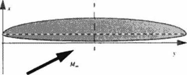
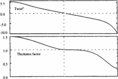
Figure 14# Wing geometry parameters: planform, twist distribution and thickness factor along span; support airfoils and their blending weight. |
We use this shock-free, redesigned airfoil as the center section for an OFW We take the planform to be comprised of two ellipses, as shown in Figure 148. w ith an overall 10:1 axis ratio providing an unswept aspect ratio of 12.7. Other airfoil sections are developed for slightly higher and lower Mach numbers based on the variation of the normal Mach number down the wing as determined previously using linear theory. We then use the geometry generator of Chapter 9 to determine a blending of candidate w ing sections. Numerical computations were performed using NASA Langley’s CFL3D (4381. И39]. To achieve the elliptic load distribution, twist is varied along the wing span. Die twist variation is linear near the center, strongly decreases at the trailing tip. and slightly increases at the leading tip But different Mach numbers and sweep angles require differing twists An elliptic loading is therefore best realized by bending the wing up at the tips. For simplicity we have used wing twist in our studies.
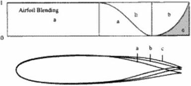
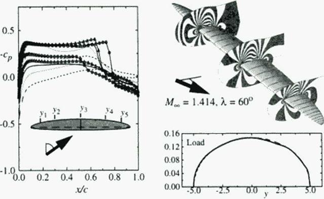
In Figure 148 we depict the blending of supercritical sections and the variation of twist used to achieve a nearly elliptic loading at the shock-free design point. Die twist was varied from – It) to -1-5.5 degrees; a wing section thickness factor varied from 0.3 to 1.5 from the trailing to the leading tip. Between the center section and trailing lip. the three support airfoils shown were blended to comprise the w ing This provided an inviscid L/D of 14.36 at a CL of 0.15 We explored the variation in L/D with angle of attack, as shown in Figure 149. We find the maximum l/D is 14.37 at а С/ of 0.146 Die inviscid pressure distributions at five span stations, the Spoil wise load distribution, and isotachs on three grid surfaces are depicted in Figure 84 These results correct those given earlier (437).
Using the skin friction estimate prov ided earlier gives a viscous L/D of 10.19. which is consistent with the result given in Chapter 19 Higher values are surely possible as the designed wing’s volume. 152,189 cubic feet, is considerably larger than that required.
|
L/D
Figure 149 Lift-u>-drag ratio as a function of angle of attack. • denotes the shock-free airfoil design point. |
|
Figure 150 Pressure distributions at five span stations (y,-dashed. Vydotted,.Гд-solid,,v4- triangle,>’5«ctrde), and Isotachs on three grid surfaces for OFW with elliptic load distribution obtained with varying wing sections and nonlinear twist distribution. |
20.2 Conclusions
The advantages of the OFW are its low aerodynamic drag at all speeds, and its low structural weight. The variable geometry afforded by changing the wing sweep from. say. 45 degrees at take-off. to 60 degrees or higher in supersonic cruise, provides excellent subsonic, transonic and supersonic performance, low airport noise, and less concern about emissions in supersonic flight because it would fly at lower altitudes than an SCT (HSCT) in supersonic flight.
Because of its aerodynamic efficiency at transonic and supersonic speeds, it also offers the prospects of a 504 or more increase in speed on overwater routes, and as much as a 204 increase on over land routes. And it may do this at no more than current subsonic transport total operating costs because of its increased productivity. A large OFW could ultimately capture 254 of the revenue passenger miles 1440).
The OFW‘s disadvantages arc the multiple new technologies that would be introduced, its match to existing certification requirements and runway widths, the non-ideal shape for the structure required to contain cabin pressurization, the need for active control, the limited speed of Mach 1.6 or less, and the psychological impact of an unsymmctrica! configuration.
Much remains to be determined about the OFW’s aerodynamics, stmetures, and control. leading edge computational technologies should make it possible to address the acro – servo-elasticity of an OFW. If promising results arc obtained to the technical challenges of the OFW. then an experimental aircraft program is warranted to verify these findings and explore related issues. The world-wide excess military’ aircraft production capability could make an experimental aircraft program less expensive than it might otherwise be.
Adam Brown has pointed out that. “… as the size of an aircraft is increased, economies of scale can be obtained. But at some point, the engineer’s dreaded ‘square/cube’ law takes over and increasing size actually results in worse structural efficiency. The Very Large Aircraft appears to be close to this cross-over point” (441). This suggests, then, that we must side-step this dreaded law by considering new geometries Among them, the OFW’ is the aerodynamic and structural optimum. The larger an OFW’ is. the higher its aspect ratio may be. increasing further its aerodynamic performance. Thus the OFW’ appears to be an ideal candidate for a new large transport.
It is unlikely that such a radical change in aircraft design would first occur in a large commercial aircraft. Thus an OFW’ is more likely to be first introduced as a military cargo or tanker aircraft, or as a smaller supersonic transport. Because of its high efficiency and productivity. and the requirement for active control, a commercial OFW might first enter service as a cargo aircraft in order to demonstrate its safety for commercial passenger service.
Acknowledgments:
This work was partially funded by the German Alexander-Von-Humboldt Foundation through a 1991 Max Planck Research Award, and by a grant from the late W. Edwards Deming. The author thanks the DLR Gottingen for their kind hospitality. April through June. 1995.
[1] The total number of deprectairon hours cannot exceed the aulrarne umctwa) life.
[2] 15 °’ [!т+т]
The engine labor cost arc related to the mean time between repairs for the powerplant. The mean time between repairs is relaicd to length of the flight cycle (number of takeoffs) and the maximum turbine entry temperature expressed in degrees Kelvin.
[3] Instead of utm; (tic actual пий of the hydraulics as used in the American Aulines method, see use Town – beck’* expression which relates И to the empty weight of I he configuration
[4] Peter Thomsen "Concorde Reaches Middle Age" World Pits» Renew June IW0
[5] Thu it m* nue if і be pricing of the aircraft were determined b> the nurici tneclurucm. rather than the actual production cost plus profit
[6] inoperative engines with high lever arms in supersonic flight; if this determines control surface loads (mainly rudder, but also aileron, elevator) special surfaces may provide improved solutions
• after a sudden pressure loss
• special devices or differently sized devices to produce high drag may enable rapid
[7] Separation limits pressure recovery This adds pressure drag On unswept wings, nose separation produces sudden, unstable flow conditions which provide unstable flight conditions. Thu must be avoided for safety reasons. Controlled trailing edge separation – e g. on flaps – can be used to increase drag, e. g for a steper glide path or deceleration dunng approach
• On highly swept wings, leading edge separation is controlled and produces additional vortex lift which is used to increase Concorde’s lift. But these lifting leading edge vortices arc positioned above the wing at strongly reduced lifung span compared to the wing span
[8] The original A140 design was not a single point design and included (hr requirement for a communal АЗЗО/A340 wing
[9] Environmental constraints. All the designs in the study meet the FAR 36 stage 3 levels with tradeoffs as formulated in ICAO an. 16 3.5. No sonic boom or ozone depletion constraints were imposed. Sonic boom can noi be avoided, the aircraft is therefore constrained to flying over water. No adverse effects on sea mammals due to overwater flights have been recorded.
[10] The oblique wing body is unsuitable for speeds over Mach 1.4. payloads over 200 passengers and ranges in excess of 6000 km. Both its aerodynamics and structures arc too poor for higher transport performance.
[11] Bow shock over pressures between 50 to 80 N/ depending on aircraft size and mission segment.
• The aft-shock is canceled due to favorable volume-lift interference.
• The lateral distribution of the sonic boom signature is distinctively asymmetric.
The sonic boom is still too loud for unrestricted (light. The best way to improve the sonic boom is to eliminate it completely by flying below Mach 1.2. Unlike other proposed HSCTs the variable geometry oblique flying wing can cruise at these speeds with very high fuel efficiency. In terms of the overall operational loudness, the larger OFW’s provide an improvement over the smaller OFW’s because of the reduction of the number of sonic booms for the same production of scat kilometers.
Following simple sweep theory, we must examine the section design of an OFW for the normal component of velocity. At cruise conditions, the flow over an OFW is that behind the nearly conical shock wave emanating from the leading up. The wing is swept so that the component of this
flow normal to the wing’s leading edge will be sufficiently subsonic that a thick, shock-free airfoil may be found. We have assumed this sweep to be 60 degrees, and a frccstrcam Mach number of V2, giving a normal Mach number of 0.707. and a tangential component of 1.23.
Bocrstocl provides guidance on how thick a non-lifting airfoil might be if designed to be shock free (434). His results, and those of others, suggest it should be possible to design an 18% thick shock-free airfoil for a normal Mach number. Af*. of 0.76. This suggests to us that a 17% thick airfoil w ith a ct of 0.6. corresponding to a wing CL of 0.15. might be shock free for a Mach number of 0.7. The importance of a nearly shock-free design stems not from the wave drag of the cross-flow shock wave, but rather from the need to avoid separation arising from the adverse pressure gradient imposed on the boundary layer by this shock wave.
The normal component of the flow accelerates over the wing to become locally "supersonic.” The return of this component to "subsonic” cross flow is normally through a shock wave, just as it is on supercritical but not shock-free airfoils. This cross-flow shock wave adversely affects the boundary layer and. thereby, the wing’s lift and drag, just as it docs on subsonic. supercritical airfoils and wings [435].
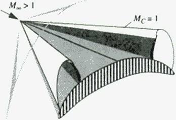
We cun fix our ideas for supersonic flow by considering supersonic conical flow past a wing with subsonic leading edges and conical camber. Such a wing will, unless designed using special tools, have a cross-flow shock wave like that depicted in Figure 146. While this flow is supersonic, the cross-flow plane equations arc mixed, being hyperbolic outside the conical shock wave and inside the local "supersonic” cross-flow region, but elliptic elsewhere
|
Figure 146 Embedded shock wave in a conical cross-flowr. |
The fictitious gas method for the design of supercritical airfoils, as discussed in Chapter 7. applies to conical supersonic flows as well. This extension to supersonic flows was first demonstrated by Snthuran [436]. Recently, wc have suggested that this method may apply to fully three-dimensional supersonic flows [437].
The axial component of the flow over the oblique wing causes a disturbance to the
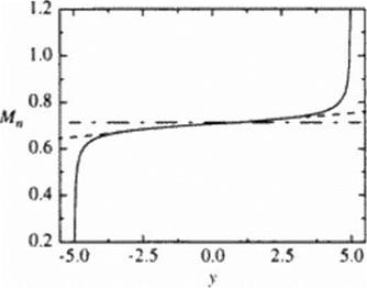
Mach number distribution of the normal component along the span. We may approximate this axial (low by that over a slender body of revolution whose cross-sectional area equals (hat of the wing, by using the linear theory. The resulting variation of the normal Mach number in the span direction is shown in Figure 147. We sec that (here is essentially a linear variation about the mid-chord value (y « 0) in the normal component of die Mach number, requiring different airfoil designs, or at least thickness, along the wing. We recognize, then, that the upper surface curvature and thickness of wing sections should be decreasing toward the w ing trailing lip. in order to avoid creating a cross-flow shock or increasing a shock’s strength if one has already formed. Our objective is to find out how well we might do in designing an OFW using supercritical airfoils that we develop and then appropriately blend to form the w ing.
|
Figure 147 Estimated variation in the normal Mach number component along the wing span; Mn • 0.707 at / = 0. Axial flow at 4, = 1.23, direction from left to right. |
As noted earlier, the OFW’ with the minimum (induced and wave) drag due to lift has an elliptic load. The OFW area distribution that minimizes the wave drag due to volume, or due to thtekness. is the Scars-Haack body for volume, and the Scars body for thickness. The former corresponds to a parabolic thickness distribution; the latter to a wing that has the same center section, but thinner outboard sections. In ihc studies reported here we have minimized the drag due to lift, and varied the thickness somewhat about a constant thickness to chord ratio. This corresponds to a nominal elliptic thickness distribution and results in more volume, and more wave drag, than necessary Thus these results should be considered very conservative, with perhaps twice the wave drag needed for the volume required for the passengers and fuel.
The studies by McDonnell Douglas Aerospace West have already been used to provide guidance on how many passengers a large OFW’ might carry, how much it might weigh, and at what speeds and altitudes it might fly. They first considered a Mach 1.6 wing swept to 68 degrees (418]. This is the design tested by NASA. They subsequently studied OFW’ designs for Mach numbers of 0.85,0.95. and 1.3 over a large range of sizes. These designs were compared to point designs for a conventional subsonic transport and a blended wing body at M = 0.85. At this Mach number the blended wing body shows greater promise.
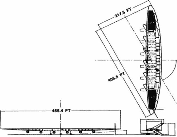
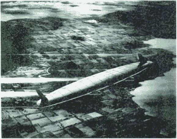
A subsequent study concluded that a Mach 1.3. 750-800 passenger OFW. with a 5200 nautical mile range, would require an unswept aspect ratio of about 10 |419J. With a passenger cabin height of 82 inches and a nominal airfoil thickness of 17%. the chord becomes about 55 feet and the span about 455 feet. This results in a wing area of 20.788 square feet, a volume of 109.660 cubic feet, and an aircraft takeoff gross weight of 1.6 million pounds, with 0.75 million of this weight in fuel. A sweep angle of 62.5 degrees was used; with M = 1.3 this provides a nominal normal Mach number of 0.6 and an estimated UD of 10.75. This aircraft is depicted in Figure 145.
|
Figure 145 McDonnell Douglas A# = 1.3 OFW capable of carrying 800 passengers 5146 nautical miles (Ref. {419]). |
Waters, et al. studied the design of OFWs. They considered their aerodynamics, structures, and layout (429). This first comprehensive study highlights several critical issues for OFWs. Principal among them were the design of the structure to carry the pressurization load, and the design of the landing gear to meet FAA taxi bump requirements
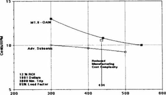
Galloway ct al. assessed the economics of 200. 400 and 500 passenger subsonic transports (M = 0.85). 300 passenger OWAs operating at Mach numbers 1.6 and 2.0. a 400 passenger OWA operating at Mach 2. and 291.440. and 544 passenger OFWs operating at Mach 1.6 (430). They assumed a five year development penod, with 500 aircraft produced in the 15-year delivery schedule.
Aircraft prices varied from $114M to S158M for the subsonic transports, from S172M to S239M for the OWAs. and from S212M to S260M for the OFWs. For a manufacturer and the operating airlines to achieve a 12# return on their investments required II to 10.1 cents per Revenue Passenger Mile (RPM) for the subsonic transports, decreasing with increasing size. 12.4 to 12 cents per RPM for the OWA and 14.2 to 111 cents per RPM for the OFWs. again decreasing with increasing size. Tins trend toward economic equality between OFWs and advanced subsonic transports is depicted in Figure 144. The fares on a large OFW should compete well w ith the fares of its subsonic counterparts.
![]()
|
D*«tgn PaiMitgw Сараеву Figure 144 NASA Amts economic assessment of the revenue required per RPM to provide a 125fc returnon investment (RODfor advanced subsonic transports, and for a M = 1.6 OFW (OAW) aircraft as a function of size (from Ref. [430]). |
Computational Fluid Dynamics tools were used extensively to optimize a realistic Mach 1.6 OFW design with the wing swept to 68 degrees |431) Related numerical studies were also conducted by Cheung (4321. This optimized design, and that by McDonnell Douglas reported in the following section, were tested in the NASA Ames 9- by 7-fool Supersonic Wind Tunnel at Mach number 1.6 |433|. The NASA design was tested at Mach numbers between 1.56 – 1.80 w ith unit Reynolds numbers of 1.0 to 4.5 million per foot. The angle of attack was varied from 0 to 6 degrees at a single sweep angle of 68 degrees. The 1.8Я – scale model included four nacelles and two vertical fins, one on the top and the other on the bottom of the trailing tip. The results of these studies are not yet published Preliminary results indicate that the experiments validate the numerical studies which resulted in a design that, while not optimum, was realistic in layout The experimental wing alone L/D. corrected to flight conditions at 52.000 feet, gives an estimated L/D оf 10 5 (private communication. R. Kcnnclly).
After their own in-house study of an OFW transport, the Boeing Company, under contract from NASA, developed an OFW design that would fit current airport designs and mccl current FAA requirements. To satisfy the FAA requirement that the passengers face no more than 18 degrees away from the flight direction on takeoff and landing (or have head restraints), the aircraft was designed to take off without sweep, which required folding wing lips. The landing gear track w as set at 60 feet
The FAA requirement on passenger orientation is. of course, met by. and may agree with, the upper deck seat angles on Boeing 747 aircraft One may argue that if passengers were seated facing rearward in a seat with side head cushions, a much larger angle might be permissible.
Passenger entry and emergency egress, engine and landing gear integration, as well as airport compatibility and terminal utilization were studied (428). Four engines are placed under the passenger compartment. This configuration, because it is designed to take off without sweep, could not become the New Large Aircraft. Nevertheless it could accommodate 440 to 460 passengers and demonstrated an OFW could be designed with existing regulatory constraints.
As hU Ph D. thesis at Stanford. Van dcr Velden undertook the development of a general evaluation tool for preliminary design of commercial supersonic aircraft, including the OFW (423)- |42SJ. This resulted in the preliminary design of an OFW that provided additional impetus and guidance to the NASA Systems Analysts Branch in their own studies of such aircraft.
Morris, in his Stanford Pti D. thesis, examined the integrated aerodynamic/control system needed for a rigid oblique wing aircraft (OWA). that is. an oblique wing with fuselage (426). He showed that by tilting the pivot axis, adverse coupling could be reduced and handling qualities improved. He subsequently extended these studies to the integrated aerodynamic and control system design of an oblique flying wing. The configuration matched that of a NASA design for a 400 passenger OFW |427|. Moms noted the utility of designing the control law for the principal axes. He then demonstrated this control law with two radio-controlled OFWs. The first was ten feel in span and flew successfully at up to 65 degrees sweep. The second was a twenty foot span OFW powered by two pivoting. 5 horsepower, ducted fan engines. Ten 25% chord trailing edge flaps were controlled by a Motorola 68020 CPU and a 68881 math coprocessor. The aircraft was designed to be able to fly at sweep angles from 35 to 65 degrees. Flight sensors were a З-axis rate gyro, a 2-axis wind sane and an airspeed indicator.
|
Figure 143 Л NASA vtbt’i concept of an OFW. |
In addition to the ten trailing edge control surfaces, two Hying vertical fins, two throttles and four landing gear stmts were driven by commercially available actuators. Actuator bandwidth limited the static stability margin to -1.8*$. This aircraft Hew in May 1994. successfully completing a four minute flight circling the field twice, changing its sweep from 35 to 50 degrees and back It circled the field by turning toward the trailing tip. which resulted in sweep angles as low as 20 degrees because of the high damping in yaw. Morris, his model aircraft, and some of his results are depicted in some Figures of Chapter 19.
The recent interest in OFWs derives from studies at Stanford by R. T. Jones. A. Van der Velden and his thesis advisor, I. Kroo. The early Stanford studies by Jones led to studies by the Systems Analysis Branch at NASA Ames, a Boeing in-house assessment of the concept, and contractual studies funded by NASA at Boeing. McDonnell Douglas, and Stanford. These culminated in wind tunnel tests of two candidate w ings as well as small radio controlled models to evaluate low speed stability and control issues.
An excellent synopsis of the NASA supported work is provided by Galloway el al.. who describe these studies and discuss the conclusions NASA drew from their own. and the contracted investigations [422]. Some of the discussion that follows derives directly from this report. A NASA artist’s concept of an OFW is shown in Figure 143.
Studies by McDonnell Douglas Aerospace West provide guidance on how many passengers a large OFW might carry, how much it might weigh, and at what speeds and altitudes it might fly for the Mach number range 1.3-1.6 (418]. (419]. We choose a frecstrcam Mach number of !2 for simplicity, and a sweep angle of 60 degrees for ease of control and acroelastic stability Higher speeds are possible with more sweep, but the wing’s control becomes increasingly difficult, with 60 degrees being judged acceptable in previous studies.
These parametric studies guide us to conclude that a high aspect ratio. 800 passenger aircraft will have a wing with a maximum chord of about 55 feet and a span of about 550 feet. This 10-1 maximum chord to span ratio provides an aspect ratio of 12.7. a wing area of 23.758 square feet and a wing volume of 127.815 cubic feet. This OFW should have a trans-Pacific nautical mile range
A conservative guess as to its weight and volume provides an OFW transport that will enter cruise at about 1.9 million pounds and leave cruise ai a weight of 1.3 million pounds For nominal conditions we take the weight to be 1.6 million pounds and the cruise altitude to be 43.500 feet.
Using these results and the nominal conditions, we calculate the turbulent skin friction drag on a flat plate, and more directly, the other terms to conclude that the drag in pounds is:
D = 4.37 x 10⁴ (skin friction) ♦ 2.31 x 10⁴ (induced)
+ 5.19 x 10³ (wave-lift) ♦ 3.74 x 10⁴ (wave-volume).
Here we use the wcll-vcnftcd method of Sommer and Short, assuming adiabatic flow, to calculate the skin friction (420J, (421 ]. This drag gives an inviscid L/D of 24.4 and a viscous L/D of 14.6. The minimum drag OFW of the same thickness (but less volume) has inviscid and viscous L/D values of 26.0 and 15.2. If we correct this lifting line result using Eq. (92). the respective viscous L/IH arc reduced to 14.5 and 151.
A practical design, with the engines in the wing and only one vertical fin. should nearly achieve these L/Ds. In Chapter 19. Van der Velden describes in some detail a 250 passenger oblique wing with four external engines that cruises with its wing swept to 68 degrees at Mach 1.6 and 50.000 feet. This OFW has a 5000 nautical mile range. Its I95t thick wing has a maximum chord of about 50 feet and a span of about 370 feet. Its maximum cruise L/D is about eleven. Because the component of the Mach number normal to the wing is only 0 6. a 1991 thick wing should be possible.
The supersonic area rule tells us that the wave drag of an aircraft in a steady supersonic flow is
 |
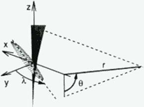 |
the average wave drag of a series of equivalent bodies of revolution. These bodies of revolution are defined by the cuts through the aircraft made by the tangents to the fore Mach cone from a distant point aft of the aircraft at an azimuthal angle 0 This average is over all azimuthal angles, as depicted in Figure 140 for an OFW For each a/imuthal angle the cross-sectional area of the equivalent body of revolution is given by the sum of two quantities: the cross-sectional area created by the oblique section from the tangent to the fore Mach cone’s intersection with the aircraft, projected onto a plane normal to the freestream; and a term proportional to the component of force on the contour of this oblique cut, lying in the 0 * constant plane, and normal to the freestream.
For minimum wave drag due to lift, each of the equivalent bodies of revolution due to lift must be a Kdrmdn ogive (408J. Likewise, for minimum wave drag due to volume, or due to thickness, each of the equivalent bodies of revolution due to volume, or due to caliber, must be a Scars-Haack. or a Sears, body (409|. (410). Because the wing also serves as the fuselage, the OFW should have a small wetted area as well. These conditions can be met by an elliptical w ing flying obliquely, so that its normal Mach number is subsonic, as Jones and Smith pointed out long ago (411). f4l2). An ellipse has ihe important characteristic «hat its chord length distribution is elliptical regardless of the angle of the chord to the center line. For minimum wave drag due to volume, the thickness distribution must be parabolic; for minimum wave drag due to thickness, the thickness distribution is more complex.
At supersonic speeds the wing must be swept to a sufficient angle that it functions efficiently as a high Mach number subsonic wing in the cross-flow normal to the w ing This then requires a wing derived from supercritical airfoils, or a full supercritical wing design. Since ihe wing must house the passengers, it must be a relatively thick wing in order not to be so large as to be impractical.
The drag of an oblique elliptic wing can be expressed using our theoretical understand
ing of drag at supersonic speeds. The individual components of drag arc the skin friction drag, the induced drag, the wave drag due to lift, and the wave drag due to volume. The lower bound for this drag, lor a given lift and volume, is given by
![]() L2 P 2L2 128qV2
L2 P 2L2 128qV2
2 + 2 * 4
7W7S Kqlj nlv
Here q is the dynamic pressure of the free stream. Sf the reference area for skin friction, and Cythc skin friction coefficient The first term represents the wing’s skin friction drag, which we may reasonably approximate by the turbulent drag on a rectangular flat plate of the same arcu and sircamwisc chord.
The second term is the induced drag for an elliptically loaded wing, where L is the lift. We recognize this expression as the induced drag of the w ing in the flow normal to it. that is. as L2/(1UfJ>2), where qn is the dynamic pressure of the normal flow and b is the unswept wing’s span. We then interpret the product qjr as </co$:>. b2 or qs2. where X is the sweep angle, and s is the span normal to the free stream.
The third and fourth terms arc the minimum wave drag due to lift and volume, where V is the w ing’s volume and (1* = M2 • 1. The two lengths. /, and /v. are the averages over all azimuthal angles of the individual lengths of the equivalent bodies of revolution, appropriately adjusted for the variation of the component of the force lying in the 8 = constant plane
If the loading in one oblique plane, say spanwise, is elliptical, and the wing has an elliptic plantonn. the loading w ill be elliptical in all azimuthal planes. To obtain an elliptic loading will require one or more of: wing bending; twist variation: camber variation.
If such an elliptic wing has a parabolic thickness distribution, the equivalent body due to volume in all u/imulhal planes is that of a ScarvHaack body. The wing’s thickness is set by passenger height. If we minimize the wave drag due to the wing’s thickness, lhai is due to the caliber of the equivalent body, then for the same caliber body as the Sears-Haack body, the drag is given by Eq. (109) w ith V reduced by n‘(8/9).
As noted above, the lengths in the last two term* ore the average over all azimuthal angles of the effective lengths for lift and volume for each azimuthal angle, as determined by the supersonic area rule. Thus lt is the actual length for that azimuthal plane divided by cos0. To calculate these lengths we must determine the angle at which the tangent to the Mach cone cuts the plane of the w ing.
For simplicity we assume that the wing lies in a horizontal plane. We recognize, but ignore, the fact that the wing must incline its lift vector slightly or be otherwise trimmed to offset the leading edge suction which occurs on only one side of the wing. This results in wing
plane inclination of about one degree.
If we write down the expression for the fore Mach cone depicted in Figure 140, and consider its apex to be at a large radial (and thereby axial) location, this equation becomes that for its tangent plane. This plane intersects the horizontal plane, and thereby the wing, in a line that makes an angle with the у-axis, <p. given by
tamp з ±$sin0. (110)
Now that we know the angle cut by the tangent to the Mach cone, we also know the length of the equivalent body of revolution for that plane is
/(0) * 6(sinX-(JcoeXsinO). (Ill)
The loading on the cut made through the wing is composed of two parts: that due to the lift, and that from the leading edge suction; we ignore this latter force. With these approximations we may determine the two lengths lt and /v (413):
Here m = (3 colX; for a wing with subsonic leading edge, m < I; for large sweep, that is small m. Eq. (112) gives If2 • ЦО)’2/2. Identifying 1(0) as the wing length, we see that eq. (109) is equivalent to Eqs. (50) and (108) in the previous chapters 4 and 19.
The minimum drag arising from the lift of a wing in supersonic flight, i. e., the sum of the induced drag and wave drag due to lift, was first given by Jones (411). It can also be determined by applying Kogan’s theorem (414). And this theorem can also be used to show that an oblique, clliptically loaded wing has the minimum inviscid drag for a given lift (415].
 |
|
We may use Eqs. (109) and (l 12) to determine the inviscid drag of an oblique lifting line. This gives
This is the result first derived by Jones, using the principle of combined flows (411].
(416J. The linear result for an arbitrary elliptic wing is more complex. We give the result here for an oblique wing of large aspect ratio (413):
![]() Cj) _ (cosA.)2(1 + m2)
Cj) _ (cosA.)2(1 + m2)
nA(m* +
 |
|
where m is related to the sweep angle and aspect ratio by m = (З cot л
Here A is the swept wing’s aspect ratio, that is. s2 divided by the wing area.
An oblique elliptic wing simultaneously provides large span and large lifting length. The reduction in the wave drag of an oblique wing of finite span also comes from being able to provide the optimum distribution of lift in all oblique planes.
 |
Figure 141 and Figure 142. taken from Jones (417). illustrate the aerodynamic advantages of the oblique wing. The first compares the minimum inviscid drag due to lift of an oblique elliptic wing with that of a delta wing of the same span and streamwise length. The second figure compares the wave drag due to volume of an oblique elliptic wing and a swept wing having the same aspect ratio and the same thickness.
To fix our ideas on ihc relative size of the various contributions to the total drag, and the possible maximum L/D let us consider a concrete example.
A. R. Scrhass
University of Colorado, Boulder. CO, L’SA
20.1 Introduction
In 1968. as mentioned in Chapter 1. there were 97 thousand aircraft arrivals and departures at Kennedy International Airport providing air travel for nearly 8 million passengers. By 1993, 15 million international passengers used Kennedy, hut this required only 92 thousand arrivals and departures. The introduction of the Boeing 747. DC 10 and other large aircraft, starting in 1970. made this possible. Kennedy, and many other airports, arc near their capacity. This, in part, is the motivation for large transport studies. One aircraft is naturally suited to being large and 10 flying supersonic: the Oblique Flying Wing (OFW). This aircraft represents a radical departure from past configurations.
The Oblique Flying Wing (OFW) as a moderate size SST is considered in detail in Chapter 19. As a sequel to that chapter, we review some important aerodynamic results for the OFW Next we review other studies of the OFW. We tlicn provide new aerodynamic results of our own that derive largely from ihc application of the theoretical tools developed in Chapter 7 and the geometric tools of Chapter 9. We conclude by delineating the advantages and disadvantages of an Oblique Flying Wing