Category Propellor Aerodynamics

Safety Around the Prop

The above paragraphs have covered propeller handling inside the cockpit; this section deals with handling the prop and moving around near the prop while on the outside of the aircraft. A rotating prop is an almost invisible blur and hard to see and hear when other aircraft are operating nearby. Safety around the prop is paramount at all times no matter if the prop is turning or stationary. The following are a few points to keep in mind when moving around the aircraft before and after flight. This maybe stating the obvious but accidents do happen that can be avoided.

The propeller per-flight involves the following:

• Check for leading edge knicks, cracks or dents

• Check the security of the prop spinner; it should be firmly secured in position

• Any signs of oil or fluid leaks require a more detailed inspection, which can be difficult if a prop spinner is in place. A leaking CSU can drain oil from the engine sump leading to an engine failure.

An accumulation of grass and dead bugs on the blades can lead to an unbalanced prop, plus a loss in prop efficiency due to the rough blade surface. A wipe over with an oily rag would solve this problem, along with an occasional polish with auto wax. Oil or dirt on the blades can be removed with carbon tetrachloride or a solvent; check the flight manual for the prop manufacturer’s recommendations for cleaning the prop blades

The propellers should never be used to man-handle the aircraft on the ground because this can place undue stress on the propeller and CSU. Holding onto a prop to pull or push the aircraft places bending stress on the prop blades. Maneuvering the aircraft by holding the prop at the blade root places stress on the CSU, the crankshaft and bearings. Whenever the aircraft has to be moved, always use the tow bar, recommended handgrips or taxi the aircraft under its own power. However, if you insist on using the prop, it is better to push or pull at the blade roots or the prop boss and not on the spinner, keeping in mind what was said above

Before the first flight of the day, it is usual practice to turn the prop by hand to clear the engine cylinders of ‘hydraulic lock’. ‘Hydraulicing’ as it is known, is caused by incompressible engine oil draining into the lower cylinders of a radial

Safety Around the Prop

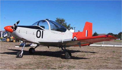
This Victa CT4B Airtrainer has a very distinctive black and white stripe on the forward side of the prop for better visibility.

engine preventing rotation during engine start-up. With the horizontally opposed type of engine, hydraulic lock is not a problem; therefore, it is not necessary to turn the engine over by hand. Nevertheless, if you do decide it must be turned over, then turn the prop in the direction of normal rotation and never backwards, as damage maybe caused to the engines ancillary equipment, such as the vacuum pump, etc. The term ‘pulling through’ or ‘hand turning’ are applied when the prop is turned by hand for reasons other than starting the engine.

A few simple rules apply to swinging the prop by hand to start the engine:

• Check the aircraft is parked into wind with the brakes ‘on’, preferably with the wheel chocks in place with the tail pointing away from the hanger and other buildings or aircraft

• The plane should be sitting on a smooth, firm surface, so you won’t slip over when you swing the prop

• Do not wear any loose clothing that may get in the moving prop

• Keep both feet firmly on the ground, one foot in front of the other so you can quickly step backwards after each swing of the prop, incase the engine starts.

Some pilots may dispute this last method having their own variation on the theme. However, what ever method is used, hand-propping is now a dying art and caution should prevail. If you have any doubts about swinging the prop, seek help from an experienced pilot or flight instructor. Besides, an experienced pilot should be at the controls any way. Hand propping solo, has on many occasions allowed the aircraft to taxi away and collide with other aircraft and buildings, etc, or become airborne with no one at the controls.

Safety Around the Prop

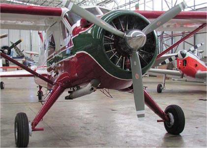
This DH Beaver has white prop tip stripes on its grey prop. The DH Chipmunk to its right also has a high-visibility prop.

A constant-speed prop can be moved fore and aft by a small amount; this movement is allowable and is known as ‘blade shake’.

Always treat the prop with care and attention it needs and deserves . In addition, always check the mags are off and the throttle closed before touching the prop. It can be a lethal device if the engine starts unexpectedly, so not touch it unless absolutely necessary. Pilots and passengers alike have a fascination for propellers and having their photos taken while hanging onto a prop blade. Imagine the result if the engine turned over! Your passengers should be warned of the dangers of the propeller and be escorted by you to and from the plane. Do not allow people to board or de-plane with the engine running Stepping off the leading edge of a low-wing plane when the prop is turning is asking for trouble because the prop is difficult to see from that position. The prop is an almost invisible disc when viewed from the rear of the plane and there are not many rotating devices in an unguarded state in any other industry. A rotating prop is as dangerous as a butcher’s ham slicer. The prop can slice off an arm or a leg quite easily. Ensure the prop is stopped before anyone gets near it

Prior to engine start, it is essential to ensure the area around the aircraft is clear of all personnel and that no one is in danger of walking into the rotating propeller. This author always used the pre-start check “all clear, front and rear” to ensure no one is in danger of walking into the rotating prop . The old method of calling “Clear prop” before starting is still a good point of airmanship, but hardly ever used these days. Turning on the rotating beacon prior to start-up also helps to warn people of your intention to start.

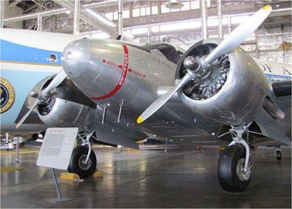
Military aircraft usually have markings – prop warning lines – on the forward fuselage to warn of the location of the propeller. However, manufacturers of civilian aircraft are reluctant to post warnings on their aircraft; is it for aesthetic

Safety Around the Prop

A prop warning line on a Beech C-54 (Model 18) Expeditor. This aircraft is located in the National Museum of the USAF, Dayton, Ohio.

reasons? They could help prevent someone from walking into the rotating propeller. On single-engine aircraft, the words “Prop” and arrows, pointing forward towards the prop, could be painted on the engine cowl. This could be a good safety feature on aero club/flying school and personal aircraft, where less experienced pilots are operating these aircraft and taking friends along for rides

Safety around the prop is the pilot-in-command’s responsibility at all times, either from inside the cockpit or outside the aircraft.

Conclusion

The workings of an aircraft propeller involve many variables Some factors work together to enhance the prop’s efficiency while other factors oppose efficiency. The result is a propeller suitable for one aircraft may not be suitable for another. Propeller design has seen many changes over the years; changes in blade planform and tip shape and also changes in materials used in their manufacture. All these changes enhance the efficiency of the aircraft propeller. How will the design of future props change? And what benefits will they have over present day props? Today’s props generate greater thrust more efficiently than the props mounted on aircraft of years gone by. Their performance has improved tremendously over the years. Therefore, we can expect to see some new and interesting innovations in prop design in the future as new aircraft types are brought onto the flight line.

However, it is not only new aircraft types that are benefitting from the new prop designs, because new props are now being deigned for individual aircraft types both old and new. It is no longer necessary for the aircraft designer to choose ‘off the shelf’ propellers as was once the case. The prop manufacturers are refining the prop’s design, so now props with three blades producing better cruise speed performance on aircraft which were once powered by two-blade props.

There is no doubt the prop is an ideal thrust generator for aircraft flying in the lower speed range, below 350 knots and will always remain so. Since the early 1960s, the jet engine has reigned supreme as the prime mover of large transport aircraft. With the advent of the Propfan design in the later half of the 1970s, will the propeller go full circle (pun intended) to make a comeback and once again power the medium to large aircraft of the future’s airlines? Maybe not. With more than half the world’s aircraft powered by propellers driven either by piston-engine or turbine power, the propeller powered aircraft is going to be with us for many years to come.

Reverse Thrust

Following an engine failure, the CSU will decrease the blade angle to fine/flat pitch in an attempt to maintain RPM as the propeller’s rotational velocity decreases. If the prop were the reversible pitch type, the blades would go into reverse pitch if it were not for the fine/flat pitch stop or the autofeathering system, if installed. A squat switch on the undercarriage, or release triggers on the throttle, or some other method is used to remove the fine/flat pitch stop in order to allow the prop blades to move into reverse pitch. Needless to say, reverse pitch should never be selected until the aircraft is firmly on the ground, due to the possibility of an excessively high and dangerous rate of decent. If one prop fails to return to forward thrust, a severe asymmetric condition will result. This has actually happened with fatal results.

Full throttle produces full thrust but zero thrust is produced with the throttle slightly open. When the throttle is fully closed, a small amount of negative thrust or prop drag is present. With the aircraft firmly on the ground, reverse thrust is applied by retarding the throttle through the gate or detent to idle reverse. This action will turn the blades via the CSU to a fixed negative blade angle of around 30 degrees past the fine/flat pitch stop. At idle reverse, the prop will produce about 60% of the maximum reverse thrust available. Further retardation of the throttle lever, will power the prop to a higher RPM than reverse idle to produce the total amount of reverse thrust available. Full aft movement of the throttle lever produces full reveres thrust caused by the increase of engine power absorbed by the prop. Reverse idle may provide sufficient braking force on long runways without the need to go to full reverse thrust. A turboprop produces about one third of its maximum shaft horsepower (SHP) when full reverse is applied, reducing the landing roll by about one quarter to one third of the unassisted reverse thrust landing distance.

Another advantage of reverse thrust is the fact it destroys the wing’s lift placing more weight on the undercarriage wheels for increased braking. The disadvantage here is the degraded elevator effectiveness; all the wheels should be firmly on the ground to prevent the nose-wheel dropping on quite.

To achieve maximum benefit of reverse thrust it should be applied fully and early as possible in the landing roll. It is more effective at higher speeds just after touchdown than it is when the landing roll is nearly complete. This is due to the fact, the aircraft’s kinetic energy is destroyed quicker and the reverse thrust force is greater due to the addition of the aircraft’s forward velocity. As the aircraft decelerates, the prop blade’s negative angle of attack reduces with the result, the reverse thrust also reduces. Reverse thrust should be cancelled when the aircraft’s ground speed is down to around 40-50 knots. However, there are some exceptions to this rule; check the aircraft’s flight manual (POH). Reverse thrust should be avoided if possible when operating on unsealed airstrips due to gravel damage to the blade’s leading edge and foreign object damage to the engine.

It is possible to taxi the aircraft backwards using reverse thrust, but the brakes should be used with caution to prevent the aircraft tipping on its tail. Visibility behind the aircraft is also a problem

Simulated Zero Thrust

It was mentioned earlier, pilots of multi-engine aircraft should be proficient at shutting down the engine and feathering the propeller in flight. Some training maneuvers require simulating an engine failure and this should be done at a safe altitude where possible. At low altitudes such as just after take-off, any training advantage gained in shutting down the engine are far out-weight by the risks involved if mishandled. Therefore, to avoid having to shut down the engine completely, the throttle can be set to simulate zero thrust. If the engine is throttle right back to the idle position, the prop will produce greater drag than when it is feathered, opening the throttle slightly to produce about 11 inches HG manifold pressure, prop drag will be overcome. The actual power setting will vary between each aircraft type and this can be found in the aircraft’s flight manual (POH). With the throttle slightly open, the prop will produce a small amount of thrust equal to the prop drag. A state of balance will then exist with the net result, zero thrust will be simulated.

Negative Torque System

Under certain flight conditions with the engine throttled back to idle and the prop in fine/flat pitch, the prop may produce zero thrust, or drag. The drag in this condition is known as the ‘flat plate drag’. Imagine the prop disc as being a large solid plate. Turboprops with their large diameter props are particularly susceptible to drag under this condition, the fixed-shaft turboprop being affected more than the free-shaft turbine engine. The CSU would naturally select a fine/flat pitch setting, but this produces the highest drag and negative torque with the engine idling. To alleviate the high drag and negative torque at low power, turboprop engines employ a negative torque system incorporated within the CSU/reduction gear assembly. The negative torque system senses when negative torque is being produced by the prop and commands the CSU to turn the blades to a more coarse pitch setting. At this setting the blade angle will be correct to absorb a predetermined amount of horsepower. As soon as the negative torque is removed with increased power selection, the CSU resumes normal operation

Autofeathering

Autofeathering is a feature more common on large transport aircraft, particularly turboprop transports. A turboprop with a reduction gear of around 20 to 1 will have its engines driven up to a speed of twenty times the prop speed. This could place enormous stress on the transmission between the engine and propeller and cause excessive prop drag. With the engine being driven by the prop, the negative torque sensor will activate the autofeathering system and feather the blades automatically.

The autofeathering system operates on a different basis to the negative torque system, which senses when the engine is still running under power but producing negative thrust, as opposed to an autofeathering system that senses a failed engine condition and turns the prop blades into the feathered position. The negative torque system operates on a continuous basis ‘as required’ at low power settings. Autofeathering acts only once – when the engine has failed.

Ground Feathering

When shutting down an engine in flight, the centrifugal force produced by the windmilling prop holds open a spring loaded ‘start lock’ allowing the blades to move through the coarse pitch stop into the feathered position. However, when shutting down the engine on the ground, the spring will override the decreasing centrifugal force and close the start locks as the prop speed decreases through 800 RPM on piston-engines, thus preventing the blades from feathering on shut down.

On aircraft with free-shaft turboprop engines, such as the P & W PT6A, the propellers always park in the feathered position as opposed to the propellers of a fixed-shaft turbine engine and on most piston-engines, which park in fine/flat pitch. The free-shaft turboprop does not have or need start locks; the blades will turn to the feathered position when the engine is shut down. During start-up, the starter has only to spool up the turbine/compressor. As the gas pressure builds up, the gas generator and prop will spool up in there own time. When the RPM builds up sufficiently, the prop will automatically move out of the feathered position into fine/flat pitch.

Ground Feathering

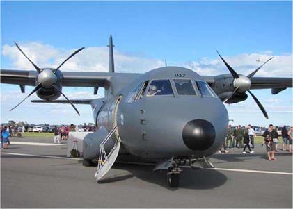
A CASA CN 235 transport parked with the props in the ground feathered position.

The advantages of feathering on shut down are prolonged windmilling is avoided and the wind will not blow the prop around when the aircraft is parked, due to lack of compression to prevent it. This will reduce danger to personnel around the aircraft. A prop brake maybe installed (known as an arrested prop system) to stop the prop’s rotation when the engine is left running during a quick turn-around between trips.

On fixed-shaft turboprops, it is impossible to stop the prop rotating because the compressor/turbine is both mounted on the same shaft. Because the compressor/turbine and propeller all turn as one unit, the propeller is parked in fine/flat pitch to reduce prop drag on engine start-up. A pitch setting other than fine will cause excessive prop drag that would retard the engine acceleration to normal idle speed resulting in a hung start. To hold the prop blades in fine/flat pitch, centrifugal start locks are incorporated in the design. Part of the engine start sequence on some turboprops is to release the start locks by selecting reverse thrust with the power levers and then returning them to the fine/flat pitch setting.

Windmilling

In the event of an engine failure, the prop will reduce speed to around 1200 RPM as it windmills. The power required to cause the prop to windmill is provided by the free air stream flowing through the prop disc. In an attempt to maintain RPM, the CSU will decrease the blade angle to the fine/flat pitch stop. However, a windmilling prop produces more drag in fine/flat pitch than it does in coarse pitch. Therefore, on a single-engine aircraft select full coarse pitch before the engine stops running. The required oil pressure to the CSU piston will be lost once the engine has stopped and then it is too late to select coarse pitch. Reduced prop drag improves the aircraft’s glide ratio enabling it to cover a greater distance in the ensuing forced landing. [See Windmilling Prop Forces].

The Feathering Prop

On multi-engine aircraft, the prop can be feathered in order to stop the engine to prevent windmilling drag and any further damage to the engine. Feathering must be achieved quickly before the engine stops, otherwise it maybe impossible to get the blades to feather. Opening the throttle a small amount maybe sufficient to increase the RPM above idle; alternatively, lowering the nose may help to keep prop windmilling long enough to feather it before reverting to safe single-engine speed (VMC). This can only be done if altitude and time permits. An engine failure, on or shortly after take-off requires immediate action to get the prop feathered.

The air/oil type CSU is more suitable for twin or multi­engine aircraft; in the event of an engine failure, loss of oil pressure would allow the opposing air pressure acting on the CSU piston to turn the blades into the feathered position. The aerodynamic turning moment, which normally turns the blades towards coarse pitch, would no longer be of assistance.

In fact, it is more of a hindrance due to the force being reversed when the prop is windmilling and it attempts to turn the blades towards fine/flat pitch. [See Prop Stress].

A feathered prop has its blades turned to a pitch angle of approximately 90 degrees edge-on to the air flow to reduce aerodynamic drag and vibration caused by the disturbed slipstream flowing over the wing and tailplane. Due to the blade’s twist, only the middle portion of the blade is parallel to the airflow, while the blade’s inner and outer portions are presented to the airflow at a positive angle of attack in opposing directions; this will tend to rotate the prop in opposing directions with the net result, the prop remains stationary

Feathering the prop in flight can be achieved by various methods depending on the design installation. These methods are:

• Manually moving the prop pitch lever through a detent on the throttle quadrant

• The use of a feathering button to activate an electro­mechanical pump, or

• An auto-feathering system.

Some of the smaller and lightweight composite props employ a blade counterweight system to assist the pitch change mechanism. When an engine fails, the counterweights will automatically cause the blades to turn towards the feathered position instead of their natural tendency to turn towards fine/flat pitch.

The pilot should be familiar with the feathering and un­feathering procedure for his/her aircraft. If an engine is shut after a real failure, it is the usual practice to leave it so and carry out a single-engine landing as soon as possible. The decision to restart an engine after a failure should not be taken lightly, because of the risk of fire, further engine damage, or the inability to re-feather the prop again if a re-start is not possible.

It should be kept in mind when feathering a prop for training purposes, in cold weather the oil in the CSU may become congealed quickly. Congealed oil can impair the operation of the CSU and present difficulties in un-feathering the prop again at the end of the exercise.

Un-feathering the prop is a relatively simple procedure that can vary between different aircraft types. It also depends if an oil pressure accumulator is used for un-feathering the propeller. For a given type and model of aircraft, some have accumulators and others do not. It is imperative to know the correct procedure for the aircraft. The accumulator holds oil under pressure and when activated oil is directed to the CSU to un-feather the prop. This is a one-time method only, so if it does not work correctly the first time you could be stuck with a feathered prop until after landing.

After selecting the coarse pitch for less prop drag or fine/flat pitch if an oil pressure accumulator is used, the engine starter is engaged. Oil pressure returning to the CSU as the engine comes back to life, will move the blades out of the feathered position. With the slipstream acting on the prop blades, the engine will start easier than it does on the ground. However, expect a fair amount of vibration until the engine has returned to active duty at the normal engine RPM. Un-feathering can also be achieved on some aircraft by activating the feathering button to start the auxiliary pump, which will supply oil to the CSU. Un-feathering requires greater oil pressure (around 600 PSI) than that required for the initial feathering. As the prop blades move out of the feathered position, the air flow through the prop disc due to the plane’s air speed will start the prop windmilling. When the RPM passes through a pre-determined figure of around 800-1000 RPM, the feathering button is activated as the CSU returns to its automatic operation. Holding the feathering button in for too long will cause the blades to move through to the fine/flat pitch stop and cause damage. Hence, the need to deactivate the feathering button. Because there are different methods of feathering and un-feathering the prop, depending on the aircraft type, a full knowledge of the particular system and procedure is essential.

An engine shut down in flight will cool rapidly. It will need some time to warm again at a low power setting after re-start before opening up to cruise power; check oil temperatures and pressures and the cylinder head temperature gauge. The throttle should be set at the recommended manifold pressure and the prop control moved from the fine or coarse pitch setting, whichever was used for the un-feathering procedure.

Overspeed Condition

A constant-speed unit malfunction in flight may cause the prop blades to move into full fine/flat pitch and overspeed, or run-away. The engine RPM may rapidly increase and exceed the maximum limits. This maybe accompanied by a high-pitch whining sound caused by the very high prop tip-speed. The engine should be throttled back and shut down immediately. If this is not done, the engine may burn up due to failure of the lubricating system in an over-heated engine and followed by a possible engine fire. This can of course lead to the total loss of the aircraft. Alternately, the high centrifugal force on the prop blades caused by the high engine RPM may result in throwing a blade. With the prop now out of balance the engine could be torn from its mounts, with fatal results. However, it may be possible in some cases to throttle back the engine to a low power setting and air speed and land at the nearest suitable airfield.

The WW II, Boeing B17F Flying Fortress bombers were notorious for propeller run-away problems. These bombers were retrofitted with Hamilton Standard paddle-blade propellers and Hydromatic CSU’s. The low temperature at high altitude caused the oil to congeal preventing it from flowing freely to the CSU. This resulted in difficulty in feathering the prop, which induced prop run-away problems, causing some engine to be torn from the mounts with the loss of the whole aircraft in some situations. If the prop over speeds on a twin-engine aircraft, the increase of thrust produced by the extra high RPM may cause a yaw towards the good engine, the opposite way to an engine failure. On the other hand, the high RPM may cause a tremendous drop in prop efficiency and thrust. This could cause high drag resulting in a yaw in the usual direction for an engine failure. Therefore, check both engine tachometers and the vertical speed indicator. If an engine fails during the climb, the rate of climb will greatly reduce, whereas a prop overspeed will maintain, or nearly so, the rate of climb near its normal limit. The American FAA certification requirements state in the event of a governor failure the static RPM should not exceed 103% of the engine’s rated RPM. This requirement determines the position of the prop’s fine/flat pitch stop.

Reducing power

When a non-turbocharged engine is running, the manifold pressure will always be less than the ambient air pressure, which is approximately 30" Hg at sea-level. This is due to the piston in the cylinder acting like an air pump. Any change in engine RPM will cause a change in the manifold pressure due to the amount of cylinder volume swept per minute by the piston. This becomes significant when changing power settings. For example, assume a take-off power setting of 2700 RPM and a manifold pressure of 26" Hg is being used and when airborne a power setting of 24" Hg is required. If the manifold pressure is reduced to 24" Hg followed by an RPM reduction to 2400 RPM, the manifold pressure will rise back up about 1" Hg to 25" Hg. This will require a further throttle adjustment to return the manifold pressure back to the required 24" Hg. The initial rise in manifold pressure is due to the decrease in the cylinder volume swept per minute causing less suction through the manifold. To avoid having to adjust the throttle/ manifold pressure twice, simply throttle back to a manifold pressure of 1" Hg lower than that required. For example here, throttle back to 23" Hg followed by RPM reduction. The manifold pressure will then rise back up to the required 24" Hg.

A check of the aircraft’s flight manual (POH) will show a table for RPM/MP combinations. From the table it can be seen a manifold pressure of 2-3" Hg above over-square is permissible. This can be used to advantage during the initial letdown from the cruise altitude. Reducing power by 200­300 RPM first, instead of reducing MP, will not only reduce noise but it will also increase the MP as already mentioned earlier. Increased MP will produce an increase in cylinder head temperature, counteracting the drop in temperature normally associated with reduced power settings used during the descent. When the RPM has been reduced to its limit in accordance with the POH table the manifold pressure must be reduced to avoid exceeding the engine’s operating limits. Also, check the cylinder head temperatures is not exceeded. Finally, after reaching circuit height, reduce the manifold pressure from the descent/cruise setting before selecting full fine/flat pitch for landing; otherwise, the high RPM associated with full fine/flat pitch will cause excessive noise and can be objectionable to people on the ground.

The prop thrust is proportional to the manifold pressure, and RPM/blade angle. A change of MP has the greatest effect on thrust variation with RPM being constant. Conversely, changing the RPM/blade angle has less effect on thrust developed. During an approach to land, RPM is maintained at a fairly high level by using fine/flat pitch, power is varied by throttle use. In the event of a ‘go-around’, maximum thrust is quickly supplied by increasing the manifold pressure while the CSU turns the blades to a coarser pitch setting to absorb the increased power.

Lock-on

The CSU is a very reliable device but faults can, and do occur. A blocked oil feed line to the CSU will cause the blades to lock – on to the pitch setting in use at the time the blockage occurs. It maybe possible to remedy the fault by cycling the prop-pitch control to clear the blockage. However, if the blockage persists, the flight should be terminated as soon as convenient. Keeping in mind a fine/flat pitch setting can over-speed the prop and a coarse pitch can be a problem if a go-around is necessary after a baulked landing.

Governor Check

After checking the magnetos are functioning correctly, the next item on the check list is the CSU governor. The RPM is increased further into the prop governor range for cycling the prop; 2000 RPM is a normal figure to use. The prop lever is retarded into full coarse pitch where the extra blade drag will cause the RPM to rapidly drop. When this occurs, the prop control must be quickly and smoothly returned to the fine position. The RPM should then return to its original value to indicate the blades are moving freely throughout the entire pitch range and returning to the fine/flat pitch stop, ready for take-off. If the engine has just been started from cold, cycle the props three times; if the engine is warm, twice should be sufficient. Cold oil in the system, either from standing overnight or from flying at high altitude, will be too thick to operate the system smoothly and the prop may hunt, it will not maintain the required RPM. Hence the need to cycle the prop three times on the first start-up of the day to ensure the thin oil is flowing freely through the CSU. Therefore check oil temperatures are in the green before run-up. During the prop cycling, the prop should respond to the coarse pitch selection within 2-3 seconds of coarse pitch application. If it does not, it requires the attention of a power plant technician.

The next checklist item if the prop is of the feathering type, especially during the first run-up of the day, is to check the feathering system. After checking the magnetos and cycling the prop, the engine is throttled back to 1700 RPM or thereabouts depending on the type The prop pitch lever is then retarded to the feathering gate where initially there should be no change in the RPM; an RPM change indicates a faulty CSU. Retarding the prop pitch lever through the gate into the feathering position, results in an RPM drop due to propeller drag; the prop blades are at a 90 degree angle to the relative airflow when the aircraft is stationary. The RPM will drop to about 600-800 RPM and the sound of the engine changes from a steady hum to a throbbing sound as the blades turn into the feathered position. With this change in engine sound, the prop pitch lever is then returned to its fine/flat pitch position. The RPM should not be allowed to drop below 1000 RPM because this will place undue stress on the engine. In cold weather, the oil in the CSU may not initially run freely preventing a smooth PRM drop when performing the feathering check Repeat the procedure until the RPM drops evenly.

The term feathering is taken from boat rowing where the oar blade is turned parallel to the water’s surface as it is returned ready for the next rowing stroke.

Running Square

During normal cruise flight, a power setting of 24 inches Hg manifold pressure and 2400 RPM would be a commonly used figure for modern light aircraft with a normally aspirated (non-turbocharged) engine. This power setting is known as ‘running the engine square’ or, ‘24 square’ for short. [Knock off the last two digits of the RPM number; in this example it is 2400 minus the last two zeros to equal 24]. If the manifold pressure is increased to a higher figure than the 2400 RPM the engine would be running ‘over square’.

Conversely, at a manifold pressure below 24" Hg the engine would be running ‘under square’. During the normal operation of a non-turbocharged engine, it is usual practice to run the engine either square or under square. Except for turbocharged engines, running the engine over square is not normally recommended for low time pilots new to constant – speed props.

Running some engines too far over square results in over­boosting which can cause serious damage to the engine in the form of pre-ignition, detonation and high cylinder head temperatures. To avoid this problem a set sequence is recommended to increase or decrease power settings When increasing power, lead with the RPM/pitch control lever followed by the MP/throttle control. The procedure is reversed for decreasing power; reduce MP/throttle first followed by the RPM/pitch change. However, there is an exception to the rule, which will be discussed shortly.

Propeller Operation

Magneto Drop & Leaning the Mixture

During the pre-take-off engine run-up, the magnetos are checked at around 1700-1800 RPM. At this stage the propeller pitch is at the fine/flat pitch limit stop and remains there during the engine run-up and until after the take-off is well under way. Therefore the drop in RPM will still be apparent and will not be masked by the CSU. The same applies to leaning the mixture if this is necessary before take-off, as would be the requirement when operating from a hot and high airfield. Lean the mixture until the RPM rises to its maximum peak. The exhaust gas temperature (EGT) will also be at its peak indicating the correct mixture setting for maximum power. When the RPM is at its peak, note the position of the mixture control and then quickly return it to ‘full rich’. The engine should continue to run smoothly without any surge in power. Continued smooth running indicates the chosen mixture setting was correct and the mixture control can now be returned to the continuously noted position