Uncertainties Induced by Variation of the Trailing-Edge Geometry
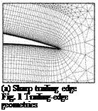
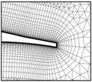
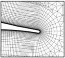
In addition to the original NLF(0)416 trailing-edge geometry, an airfoil with a blunt trailing edge was used. Following Somers [5], the blunt trailing edge was obtained by attaching a wedge on the last five percent of the airfoil. With this wedge the trailing edge gets a bluntness of 0.5% of chord length. As a further variant a NLF(0)416 airfoil with a rounded trailing edge was used. This airfoil was derived from the airfoil with the blunt trailing edge by replacing the corners with radii. The airfoils with sharp as well as blunt trailing edges were discretized using both c – and o-type topology. The airfoil with round trailing-edge geometry was only meshed with an o-type grid since no reasonable c-type discretization was possible. In addition, the grid c – grid, 4x was derived from the initial c-grid by doubling the number of grid points in both coordinate directions. Figure 1 depicts the grid topologies for the respective trailing edge variants. The numerical results obtained on these three grids are shown in Figure 2. Note that the experimental results on the blunt trailing edge are not depicted in this figure, since the experiments show no influence of the trailing edge geometry in this particular case. The blunt trailing edge leads to a higher drag coefficient in general. Due to the modification of the geometry one gets a difference of 2.0 drag counts in cd. In the experiments the initial airfoil has a trailing-edge separation. Because of this a flow pattern similar to the flow around the blunt trailing edge appears. But in case of the numerical results only attached flow is present for a = 4° to 12°.
 |
|
 |
 |
Furthermore, one can observe that the blunt trailing edge yields lower lift coefficients across the whole a-range. This can be attributed to the decambering effect of the wedge attached on the airfoil.
(b) Blunt trailing edge (c) Rounded trailing edge
|
Fig. 2 Polar curves for different trailing edge geometries |


