THE BASIC LONGITUDINAL FORCES
The basic flight condition for most vehicles is symmetric steady flight. In this condition the velocity and force vectors are as illustrated in Fig. 2.1. All the nonzero forces and motion variables are members of the set defined as “longitudinal.” The two main aerodynamic parameters of this condition are V and a.
Nothing can be said in general about the way the thrust vector varies with V and a, since it is so dependent on the type of propulsion unit—rockets, jet, propeller, or turboprop. Two particular idealizations are of interest, however,
1. T independent of V, that is, constant thrust; an approximation for rockets and pure jets.
2. 7У independent of V, that is, constant power; an approximation for reciprocating engines with constant-speed propellers.
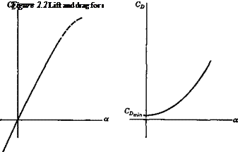
The variation of steady-state lift and drag with a for subsonic and supersonic Mach numbers (M < about 5) are characteristically as shown in Fig. 2.2 for the range of attached flow over the surfaces of the vehicle (McCormick, 1994; Miele, 1962; Schlichting and Truckenbrodt, 1979). Over a useful range of a (below the stall) the coefficients are given accurately enough by
![]() (2-1,1)
(2-1,1)
(2.1,2)
The three constants CLn, CDmjn, К are principally functions of the configuration shape, thrust coefficient, and Mach number.
 |
Significant departure from the above idealizations may, of course, be anticipated in some cases. The minimum of CD may occur at a value of a > 0, and the curvature of the C[ vs. a relation may be an important consideration for flight at high CL. When the vehicle is a “slender body,” for example, a slender delta, or a slim wingless
W
Figure 2.1 Steady symmetric flight.
 |
body, the CL curve may have a characteristic upward curvature even at small a (Flax and Lawrence, 1951). The upward curvature of CL at small a is inherently present at hypersonic Mach numbers (Truitt, 1959). For the nonlinear cases, a suitable formulation for CL is (USAF, 1978)
CL = (ІСдг. sin 2a + CNaa sin a jsin aj) cos a (2.1,3)
where CNa and CNaa are coefficients (independent of a) that depend on the Mach number and configuration. [Actually CN here is the coefficient of the aerodynamic force component normal to the wing chord, and CNa is the value of CLa at a = 0, as can easily be seen by linearizing (2.1,3) with respect to a.] Equation (2.1,2) for the drag coefficient can serve quite well for flight dynamics applications up to hypersonic speeds (M > 5) at which theory indicates that the exponent of CL decreases from 2 to f. Miele (1962) presents in Chap. 6 a very useful and instructive set of typical lift and drag data for a wide range of vehicle types, from subsonic to hypersonic.


