DEVELOPMENT OF AERODYNAMIC FORCES
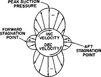
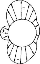
The typical airflow patterns exemplify the relationship of static pressure and velocity defined by Bernoulli. Any object placed in an airstream will have the air to impact or stagnate at some point near the leading edge. The pressure at this point of stagnation will be an absolute static pressure equal to the total pressure of the airstream. In other words, the static pressure at the stagnation point will be greater than the atmospheric pressure by the amount of the dynamic pressure of the airstream. As the flow divides and proceeds around the object, the increases in local velocity produce decreases in static pressure. This procedure of flow is best illustrated by the flow patterns and pressure distributions of figure 1.7.
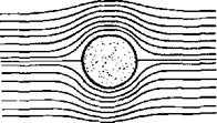
STREAMLINE PATTERN AND PRESSURE DISTRIBUTION. The flow pattern of the cylinder of figure 1.7 is characterized by the streamlines which denote the local flow direction. Velocity distribution is noted by the streamline pattern since the streamlines effect a boundary of flow, and the airflow between the streamlines is similar to flow in a closed tube. When the streamlines contract and are close together, high local velocities exist; when the streamlines expand and are far apart, low local velocities exist. At the
|
NEGLECTING FRICTION CONSIDERING FRICTION EFFECTS

(PERFECT FLUID) (VISCOUS FLOW)
Figure 1.7. Streamline Pattern and Pressure Distribution
forward stagnation point the local velocity is zero and the maximum positive pressure results. As the flow proceeds from the forward stagnation point the velocity increases as shown by the change in streamlines. The local velocities reach a maximum at the upper and lower extremities and a peak suction pressure is produced at these points on the cylinder. (Note: Positive pressures are pressures above atmospheric and negative or suction pressures are less than atmospheric.) As the flow continues aft from the peak suction pressure, the diverging streamlines indicate decreasing local velocities and increasing local pressures. If friction and compressibility effects are not considered, the velocity would decrease to zero at the aft stagnation point and the full stagnation pressure would be recovered. The pressure distribution for the cylinder in perfect fluid flow would be symmetrical and no net force (lift or drag) would result. Of course, the relationship between static pressure and Velocity along the surface is defined by Bernoulli’s equation.
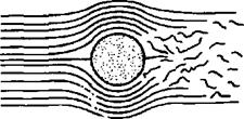
The flow pattern for the cylinder in an actual fluid demonstrates the effect of friction or viscosity. The viscosity of air produces a thin layer of retarded flow immediately adjacent to the surface. The energy expended in this “boundary layer” can alter the pressure distribution and destroy the symmetry of the pattern. The force unbalance caused by the change in pressure distribution creates a drag force which is in addition to the drag due to skin friction.
The streamline pattern for the symmetrical airfoil of figure 1.7 again provides the basis for the velocity and pressure distribution. At the leading edge the streamlines are widely diverged in the vicinity of the positive pressures. The maximum local velocities and suction (or negative) pressures exist where the streamlines are the closest together. One notable difference between the flow on the cylinder and the airfoil is that the maximum velocity and minimum pressure points on the
airfoil do not necessarily occur at the point of maximum thickness. However, a similarity does exist in that the minimum pressure points correspond to the points where the streamlines are closest together and this condition exists when the streamlines are forced to the greatest curvature. .
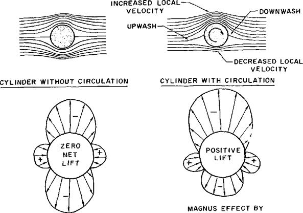
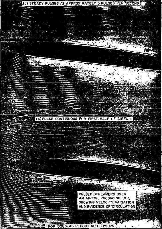
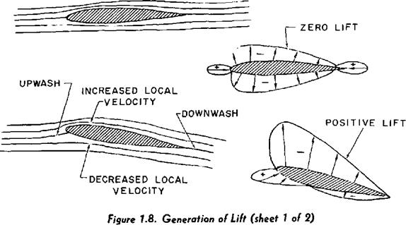
GENERATION OF LIFT. An important phenomenon associated with the production of lift by an airfoil is the “circulation” imparted to the airstream. The best practical illustration of this phenomenon is shown in figure 1.8 by the streamlines and pressure distributions existing on cylinders in an airstream. The cylinder without circulation has a symmetrical streamline pattern and a pressure distribution which creates no net lift. If the cylinder is given a clockwise rotation and induces a rotational or circulatory flow, a distinct change takes place in the streamline pattern and pressure distribution. The velocities due to the vortex of circulatory flow cause increased local velocity on the upper surface of the cylinder and decreased local velocity on the lower surface of the cylinder. Also, the circulatory flow produces an upwash immediately ahead and downwash immediately behind the cylinder and both fore and aft stagnation points are lowered.
The effect of the addition of circulatory flow is appreciated by the change in the pressure distribution on the cylinder. The increased local velocity on the upper surface causes an increase in upper surface suction while the decreased local velocity on the lower surface causes a decrease in lower surface suction. As a result, the cylinder with circulation will produce a net lift. This mechanically induced circulation—called Magnus effect—illustrates the relationship between circulation and lift and is important to golfers, baseball and tennis players as well as pilots and aerodynamicists. The curvature of the flight path of a golf ball or baseball requires an unbalance of force which is created by rotation of the ball. The pitcher that can accurately control a powerful
|
|
|
|
Figure 1.8. Generation of Lift (sheet 2 of 2) |
BASIC AIRFOIL SHAPE AND ANGLE OF ATTACK
![]()
|
|
|
AIRFOIL SHAPE AND ANGLE OF ATTACK DEFINE
RELATIVE PRESSURE DISTRIBUTION
Figure 1.9. Airfoil Pressure Distribution
rotation will be quite a “curve ball artist" the golfer that cannot control the lateral motion of the club face striking the golf ball will impart an uncontrollable spin and have trouble with a “hook” or "slice.”
While a rotating cylinder can produce a net lift from the circulatory flow, the method is relatively inefficient and only serves to point out the relationship between lift and circula-, tion. An airfoil is capable of producing lift with relatively high efficiency and the process is illustrated in figure 1.8. If a symmetrical airfoil is placed at zero angle of attack to the airstream, the streamline pattern and pressure distribution give evidence of zero lift. However, if the airfoil is given a positive angle of attack, changes occur in the streamline pattern and pressure distribution similar to changes caused by the addition of circulation to the cylinder. The positive angle of attack causes increased velocity on the upper surface with an increase in upper surface suction while the decreased velocity on the lower surface causes a decrease in lower surface suction. Also, upwash is generated ahead of the airfoil, the forward stagnation point moves under the leading edge, and a downwash is evident aft of the airfoil. The pressure distribution on the airfoil now provides a net force perpendicular to the airstream—lift.
The generation of lift by an airfoil is dependent upon the airfoil being able to create circulation in the airstream and develop the lifting, pressure distribution on the surface. In all cases, the generated lift will be the net force caused by the distribution of pressure over the upper and lower surfaces of the airfoil. At low angles of attack, suction pressures usually will exist on both upper and lower surfaces but the upper surface suction must be greater for positive lift. At high angles of attack near that for maximum lift, a positive pressure will exist on the lower surface but this will account for approximately one-third the net lift.
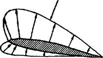
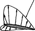
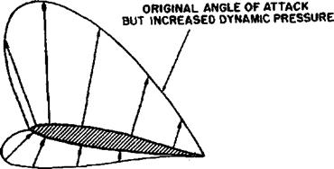
The effect of free stream density and velocity is a necessary consideration when studying the development of the various aerodynamic forces. Suppose that a particular shape of airfoil is fixed at a particular angle to the airstream. The relativ» velocity and pressure distribution will be determined by the shape of the airfoil and the angle to the airstream. The effect of varying the airfoil size, air density and airspeed is shown in figure 1.9. If the same airfoil shape is placed at the same angle to an airstream with twice as great a dynamic pressure the magnitude of the pressure distribution will be twice as great but the relative shape of the pressure distribution will be the same. With twice as great a pressure existing over the surface, all aerodynamic forces and moments will double. If a half-size airfoil is placed at the same angle to the original airstream, the magnitude of the pressure distribution is the same as the original airfoil and again the relative shape of the pressure distribution is identical. The same pressure acting on the half-size surface would reduce all aerodynamic forces to one-half that of the original. This similarity of flow patterns means that the stagnation point occurs at the same place, the peak suction pressure occurs at the same place, and the actual magnitude of the aerodynamic forces and moments depends upon the airstream dynamic pressure and the surface area. This concept is extremely important when attempting to separate and analyze the most important factors affecting the development of aerodynamic forces.
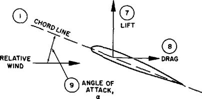
AIRFOIL TERMINOLOGY. Since the shape of an airfoil and the inclination to the airstream are so important in determining the pressure distribution, it is necessary to properly define the airfoil terminology. Figure 1.10 shows a typical airfoil and illustrates the various items of airfoil terminology
(1) The chord line is a straight line connecting the leading and trailing edges of the airfoil.
|
|
|
Figure 1.10. Airfoil Terminology |
(2) The chord is the characteristic dimension of the airfoil.
(3) The mean-camber line is a line drawn halfway between the upper and lower surfaces. Actually, the chord line connects the ends of the mean-camber line.
(4) The shape of the mean-camber line is very important in determining the aerodynamic characteristics of an airfoil section. The maximum camber (displacement of the mean line from the chord line) and the location of the maximum camber help to define the shape of the mean-camber line. These quantities are expressed as fractions or percent of the basic chord dimension. A typical low speed airfoil may have a maximum camber of 4 percent located 40 percent aft of the leading edge.
(3) The thickness and thickness distribution of the profile are important properties of a section. The maximum thickness and location of maximum thickness define thickness and distribution of thickness and are expressed as fractions or percent of the chord. A typical low speed airfoil may have a. maximum thickness of 12 percent located 30 percent aft of the leading edge.
(6) The leading edge radius of the airfoil is the radius of curvature given the leading edge shape. It is the radius of the circle centered on a line tangent to the leading edge camber and connecting tangency points of upper and lower surfaces with the leading edge. Typical leading edge radii are zero (knife edge) to 1 or 2 percent.
(7) The lift produced by an airfoil is the net force produced perpendicular to the relative wind.
(8) The drag incurred by an airfoil is the net force produced parallel to the relative wind.
(9) The angle of attack is the angle between the chord line and the relative wind. Angle of attack is given the shorthand notation a (alpha). Of course, it is important to dif-
I ferentiate between pitch attitude angle and
angle of attack. Regardless of the condition of flight, the instantaneous flight path of the surface determines the direction of the oncoming relative wind and the angle of attack is the angle between the instantaneous relative wind and the chord line. To respect the definition of angle of attack, visualize the flight path of the aircraft during a loop and appreciate that the relative wind is defined by the flight path at any point during the maneuver.
Notice that the description of an airfoil profile is by dimensions which are fractions or percent of the basic chord dimension. Thus, when an airfoil, profile is specified a relative shape is described. (Notb: A numerical system of designating airfoil profiles originated by the National Advisory Committee for Aeronautics [NACA] is used to describe the main geometric features and certain aerodynamic orooerties. NACA Report No. 824 will provide the detail of this system.)


