EFFECT OF LINEAR LIFT AND MOMENT ON NEUTRAL POINT
When the forces and moments on the wing, body, tail, and propulsive system are linear in a, as may be near enough the case in reality, some additional useful relations can be obtained. We then have
CLwb = awbawb (2.3,9)
Q, = ata, (2.3,10)
dCm
and Cmp = Cm0p + • a (2.3,11)
If Cmwb is linear in CLwh, it can be shown (see exercise 2.3) that Cmac^ does not vary with CLwb, i. e. that a true mean aerodynamic center exists. Figure 2.11 shows that the tail angle of attack is
a, = awh ~ i, ~ e (2.3,12)
and hence CL, = a,{awh — i, — e) (2.3,13)
The downwash e can usually be adequately approximated by
є = e0+ awb (2.3,14)
da
The downwash e0 at awh = 0 results from the induced velocity field of the body and from wing twist; the latter produces a vortex wake and downwash field even at zero total lift. The constant derivative de/da occurs because the main contribution to the downwash at the tail comes from the wing trailing vortex wake, the strength of which is, in the linear case, proportional to CL.
 |
|
The tail lift coefficient then is
 or CL = {CL) о + aawh
or since awh and a differ by a constant
CL = aa
is the coefficient of the lift on the tail when awb = 0;
 |
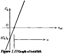
is the lift-curve slope of the whole configuration; and a is the angle of attack of the zero-lift line of the whole configuration (see Fig. 2.13). Note that, since i, is positive,
then (CL)о is negative. The difference between a and awb is found by equating (2.3,16b and c) to be
into (2.3,1) the following results can be obtained after some algebraic reduction:
Note that since Сшо is the pitching moment at zero awb, not at zero total lift, its value depends on h (via V„), whereas Cmo, being the moment at zero total lift, represents a couple and is hence independent of CG position. All the above relations apply to tailless aircraft by putting VH = 0. Another useful relation comes from integrating
(2.3,5) , i. e.
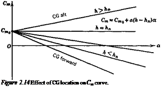
Cm = Cmo + C/(h – h„) (a)
Cm = Cmo + aa(h – hn) (b) (2.3,25)
or Cma = a(h – hn) (c)
 |
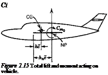
Figure 2.14 shows the linear Cm vs. a relation, and Fig. 2.15 shows the resultant system of lift and moment that corresponds to (2.3,25), that is a force CL and a couple
 |
Cmo at the NP. Figure 2.15 is a very important result that the student should fix in his mind.


