Flow Near a Hovering Rotor
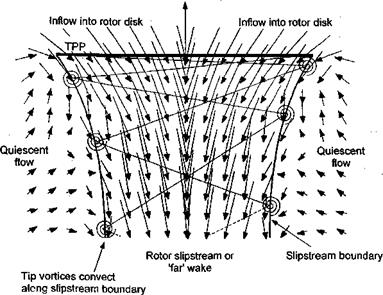
Hover is a very unique flight condition. Here, the rotor has zero forward speed and zero vertical speed (no climb or descent). The rotor flow field is, therefore, azimuthially axisymmetric. A set of velocity measurements near a subscale hovering rotor and in its wake is shown in Fig. 2.4. Notice that the fluid velocity is increased smoothly as it is entrained into and through the rotor disk plane. There is no jump in velocity across the disk, although because a thrust is produced on the rotor, there must be a jump in pressure over the rotor disk. The existence of a wake boundary or slipstream is apparent, with the flow velocity outside this boundary being relatively quiescent. The blade tip vortices trail behind and below each blade and are convected along this wake boundary. Inside the wake boundary, the flow velocities are substantial and may be distributed nonuniformly across the slipstream. Note also the contraction in the diameter of the wake below the rotor corresponding to an increase in the slipstream velocity.
|
Rotor thrust
Figure 2.4 Measurements of the velocity field in a diametric plane near and below a two-bladed rotor operating in hover. Data source: Leishman et al. (1995) |
With the physical picture of the hovering rotor flow now apparent, it is possible to approach a mathematical solution to this problem. Consider the application of the three basic conservation laws (conservation of mass, momentum, and energy) to the rotor and its flow field. The conservation laws will be applied in a quasi-one-dimensional integral formulation to a control volume surrounding the rotor and its wake. This approach permits us to perform a first level analysis of the rotor performance (e. g., its thrust and power), but without actually having to consider the details of the flow environment, that is without having to consider what is happening locally at each blade section. This approach, which is called momentum theory, was first developed by Rankine (1865) for use in the analysis of marine propellers. The theory was developed further by W. Froude (1878) and R. E. Froude (1889), Lanchester (1915), and Betz (1920a, b; 1922). Momentum theory was formally generalized by Glauert (1935) – see entry in Durand (1935). The main difference between the Froude and Rankine theories is in the treatment of the rotor disk as a series of elementary rings, versus the treatment of the disk as a whole. In either case, one fundamental assumption in the basic momentum theory is that the rotor can be idealized as an infinitesimally thin actuator disk over which a pressure difference exists. The concept is equivalent to considering an infinite number of blades of zero thickness, a concept first suggested by W. Froude. The actuator disk supports the thrust force that is generated by the rotation of the rotor blades about the shaft and their action on the air. Power is required to generate this thrust, which is supplied in the form of a torque to the rotor shaft. Work done on the rotor leads to a gain in kinetic energy of the rotor slipstream and this is an unavoidable energy loss that is called induced power.


