Transonic flow and shock waves
In flows with a subsonic freestream, or M < 1, the maximum local Mach number can become supersonic, or M > 1. Such a flow with both subsonic and supersonic regions present is called a transonic flow. An example is shown in Figure 8.6. Transonic flows will be treated in more detail later in this chapter.
8.1.2 Flow-field representation
As mentioned above, the presence of field sources creates difficulties for a calculation method using the freestream+source+vorticity superposition to represent the flow. Consider a non-lifting case which can be represented by fictitious source sheets X(s, e) to represent the airfoil, and a source density a(r) as defined
|
|
x/c
 |
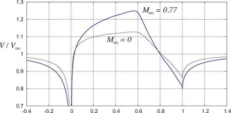
Figure 8.3: Comparison of surface speed distributions V(x) on NACA N66-010 airfoil at а = 0° at = 0 and = 0.77. Field sources and sinks increase the speed over most of the airfoil, and decrease the speed ahead and behind the airfoil.
by (8.1) above to represent the field sources. The overall velocity field is then given as follows.
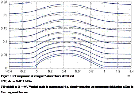
One difficulty is due to the integrand in the second superposition integral in (8.2) being nonlinear, since V2 and a2 both depend on the local V(r’). This is a relatively minor complication which could be handled with a suitable iterative solution method. The real difficulty arises from this being a volume integral, which requires a space-filling grid to enable its numerical evaluation. Such a method would then offer no advantage in the number of flow unknowns over a method which uses a grid-based flow-field representation approach. Furthermore, each unknown field source directly influences all field points, so the associated AIC matrix is large, dense, and would be dramatically expensive to solve. In contrast, in a grid-based method each flow unknown influences only its few grid neighbors, so the AIC matrices of grid methods are always very sparse and thus more economical to solve.


