Aircraft Motion and Forces
An aircraft is a vehicle in motion; in fact, it must maintain a minimum speed above the stall speed. The resultant pressure field around the aircraft body (i. e., wetted surface) is conveniently decomposed into a usable form for designers and analysts. The pressure field alters with changes in speed, altitude, and orientation (i. e., attitude). This book primarily addresses a steady level flight pressure field; the unsteady situation is considered transient in maneuvers. Chapter 5 addresses certain unsteady cases (e. g., gusty winds) and references are made to these design considerations when circumstances demands it. This section provides information on the parameters concerning motion (i. e., kinematics) and force (i. e., kinetics) used in this book.
3.6.1 Motion
Unlike an automobile, which is constrained by the road surface, an aircraft is the least restricted vehicle, having all six degrees of freedom (Figure 3.8): three linear and three rotational motions along and about the three axes. These can be represented in any coordinate system; however, in this book, the righthanded Cartesian coordinate system is used. Controlling motion in six degrees of freedom is a complex matter. Careful aerodynamic shaping of all components of an aircraft is paramount, but the wing takes top priority. Aircraft attitude is measured using Eulerian angles – f (azimuth), в (elevation), and ф (bank) – and are in demand for aircraft control; however, this is beyond the scope of this book.
In classical flight mechanics, many types of Cartesian coordinate systems are in use. The three most important are as follows:
1. Body-fixed axes, FB, isa system with the origin at the aircraft CG and the X-axis pointing forward (in the plane of symmetry), the Y-axis going over the right wing, and the Z-axis pointing downward.
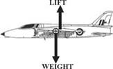
Figure 3.9. Equilibrium flight (CG at ®). (Folland Gnat: the 1960s, United Kingdom – world’s smallest fighter aircraft. Fuselage length = 9.68 m, span =
![]()
![]()
 7.32 m, height = 2.93 m)
2. Wind-axes system, FW, also has the origin (gimballed) at the CG and the X-axis aligned with the relative direction of airflow to the aircraft and points forward. The Y – and Z-axes follow the righthanded system. Wind axes vary, corresponding to the airflow velocity vector relative to the aircraft.
3. Inertial axes, FI, fixed on the Earth. For speed and altitudes below Mach 3 and 100,000 ft, respectively, the Earth can be considered flat and not rotating, with little error, so the origin of the inertial axes is pegged to the ground. Conveniently, the X-axis points north and the Y-axis east, making the Z-axis point vertically downward in a righthanded system.
In a body-fixed coordinate system, FB, the components are as follows:
Linear velocities: U along X-axis (+ve forward)
V along Y-axis (+ve right)
W about Z-axis (+ve down)
Angular velocities: p about X-axis, known as roll (+ve )
q about Y-axis, known as pitch (+ve nose up) r about Z-axis, known as yaw (+ve )
Angular acceleration: p about X-axis, known as roll rate (+ve)
q about Y-axis, known as pitch rate (+ve nose up) r about Z-axis, known as yaw rate (+ve)
In a wind-axes system, FW, the components are as follows:
Linear velocities: V along X-axis (+ve forward)
Linear accelerations: V along X-axis (+ve forward)
and so on.
If the parameters of one coordinate system are known, then the parameters in another coordinate system can be found through the transformation relationship.


