Axial Descent
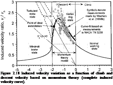
The climb flow model cannot be used in a descent (where Vc <$C 0) because now Vc is directed upward and so the slipstream will be above the rotor. This will be the case whenever I Vc I is more than twice the average induced velocity at the disk. For cases where the descent velocity is in the range —2vh < Vc < 0, the velocity at any plane through the rotor slipstream can be either upward or downward. Under these circumstances, a more complicated recirculating (and usually more turbulent and aperiodic) flow pattern may exist at the rotor. Momentum theory. cannot be used here because no definitive control volume
Climb velocity ratio, V / vh
 |
surrounding the rotor and its wake can be established – see discussion by Glauert (1935, p. 348). The same argument applies when using the blade element momentum theory (BEMT), which is discussed in Chapter 3. The more complicated operating state where —2Vh < Vc < 0 is discussed in Section 2.13.3.
The assumed flow model and control volume surrounding the descending rotor is shown in Fig. 2.19. To proceed, the assumption must be made that | Vc | > 2vh so that a well-defined slipstream will always exist above the rotor and encompassing the rotor disk. Far upstream (well below) the rotor, the magnitude of the velocity is the descent velocity, which is equal to I Vc. Notice that to avoid any ambiguity, it will be assumed that the velocity is measured as positive when directed in a downward direction. At the plane of the rotor, the velocity is I Vc| — Vi. In the far wake (above the rotor), the velocity is | Vc| — w.
 |
|
By the conservation of mass, the fluid mass flow rate, m, through the rotor disk is
with the negative sign arising because the flow direction is now reversed (upward) compared to the climb case. In a steady descent, the velocity far upstream of (below) the rotor must be
(2.86)
which is a negative quantity. Therefore, the rotor is now extracting power from the airstream and this operating condition is known as the windmill state, for obvious reasons. More usually it is referred to as the windmill brake state because the rotor in this condition decreases or “brakes” the velocity of the flow – see Chapter 13. Using Eqs. 2.85 and 2.86 it is seen, again, that w = 2d,- . Note, however, that the net velocity in the slipstream is less than I Vc, and so from continuity considerations the wake boundary expands above the descending rotor disk. For the descending rotor
![]()
T = —mw — —pA(Vc + Vi)w = —2 pA(Vc + v;)i>; Therefore, we can write
(2.90)
![]()
![]()
Again, like the climb case, there are two possible solutions for /tih. One of these solutions produces values of vi/vh > 1, which violates the assumed flow model in this case. The only valid solution is
which is valid for Vc/vh < —2. Therefore, it is noted from Fig. 2.18 that as the descent velocity increases the induced velocity decreases and asymptotes smoothly to zero at high descent rates. The other solution to the quadratic, which is denoted by the broken line in Fig. 2.18, violates the assumed flow model and so is a nonphysical solution.


