Computational method
Aim of this paper is to present a method to assess flitter stability of complex modes. As in the P-K method, the blade modeshape is approximated to a rigid motion and the row vibrates in traveling wave mode. Additionally, as in P-K, a single section of the blade (e. g. the one with the greatest displacements) is used to represent the blade 3D vibration mode.
Aeroelastic solver
During our research on Computational Aeroelasticity (CA) at the Department of Energy Engineering (University of Florence), we developed an aeroelastic solver, designed to work together with the steady/unsteady fl»w solver TRAF [Arnone, 1994].
This aeroelastic solver (named LARS, time-Linearized Aeroelastic Response
Solver) is based on the uncoupled energy approach: the blade harmonic oscillation is prescribed in terms of frequency and modeshape, and flitter stability is assessed through a work per period calculation. Quasi-three-dimensional fliid motion equations (Euler, thin shear layer or Navier-Stokes) are time-linearized about a steady solution [Hall and Clark, 1993]; this steady solution, representing the mean fl>w, is computed by TRAF in steady mode, while its harmonic perturbation, representing the fbw field unsteadiness generated by blade harmonic motion, is calculated by LARS.
Numerical stability is guaranteed through the introduction of appropriate artificial dissipation, derived from TRAF definition through frozen coefficient linearization. In order to speed up convergence, local time stepping, multigrid acceleration and residual smoothing techniques have been implemented in a way similar to that adopted for TRAF. Non-reflecting boundary conditions are used on inlet and outlet boundaries [Giles, 1988].
The solver implements both traveling wave mode and influence coefficient technique; in this work the traveling wave mode has been applied.

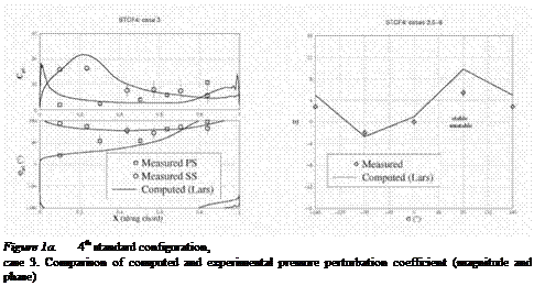
LARS was previously validated for turbine blades applications on International Standard Configuration turbine experimental data [Fransson and Verdon, 1991], in particular STCF4 (see figures 1a, 1b).
Figure 1b. 4th standard configuration,
cases 3, 6, 7, 8. Comparison of computed and experimental aerodamping coefficient


