ELEVATOR ANGLE TO TRIM
The trim condition is Cm = 0, whence from (2.4,1 d)
 „ CJa)
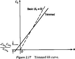
The trimmed lift-curve slope is seen to be less than CLa by an amount that depends on Cma, i. e., on the static margin, and that vanishes when h = hn. The difference is only a few percent for tailed airplanes at normal CG position, but may be appreciable for tailless vehicles because of their larger CLs. The relation between the basic and trimmed lift curves is shown in Fig. 2.17.
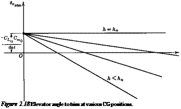
Equation (2.4,13&) is plotted on Fig. 2.18, showing how Setrim varies with CUnm and CG position when the aerodynamic coefficients are constant.
VARIATION OF 5etrlm WITH SPEED
When, in the absence of compressibility, aeroelastic effects, and propulsive system effects, the aerodynamic coefficients of (2.4,13) are constant, the variation of <5£,tnm with speed is simple. Then Seuim is a unique function of CLcr. m for each CG position. Since CUr. m is in turn fixed by the equivalent airspeed,[7] for horizontal flight
![]()
 |
W
3ft)
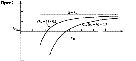
then <5,,mn becomes a unique function of VE. The form of the curves is shown in Fig. 2.19 for representative values of the coefficients.
 |
The variation of 8f, uim with C/tnm or speed shown on Figs. 2.18 and 2.19 is the normal and desirable one. For any CG position, an increase in trim speed from any initial value to a larger one requires a downward deflection of the elevator (a forward
movement of the pilot’s control). The “gradient” of the movement d8ettiJdVE is seen to decrease with rearward movement of the CG until it vanishes altogether at the NP. In this condition the pilot in effect has no control over trim speed, and control of the vehicle becomes very difficult. For even more rearward positions of the CG the gradient reverses, and the controllability deteriorates still further.
When the aerodynamic coefficients vary with speed, the above simple analysis must be extended. In order to be still more general, we shall in the following explicitly include propulsive effects as well, by means of the parameter 8p, which stands for the state of the pilot’s propulsion control (e. g., throttle position). 8p = constant therefore denotes fixed-throttle and, of course, for horizontal flight at varying speed, 8p must be a function of V that is compatible with T = D. For angles of climb or descent in the normal range of conventional airplanes L = W is a reasonable approximation, and we adopt it in the following. When nonhorizontal flight is thus included, 8P becomes an independent variable, with the angle of climb у then becoming a function of 8p, V, and altitude.
The two basic conditions then, for trimmed steady flight on a straight line are
![]()
![]()
 |
cm = o
L = CLpV2S = W and in accordance with the postulates made above, we write
Cm = Cm(a, V, 8e, 8p) CL = CL(a, V, 8e, 8P)
 |
|
Now let ( )e denote one state that satisfies (2,4,18) and consider a small change from it, denoted by differentials, to another such state. From (2.4,18) we get, for p = const,
There are two possibilities, 8p constant and 8p variable. In the first case (fixed throttle), d8p = 0 and
![]() (2.4,24)
(2.4,24)
It will be shown in Chap. 6 that the vanishing of this quantity is a true criterion of stability, that is it must be >0 for a stable airplane. In the second case, for example exactly horizontal flight, 8p = Sp(V) and the 8p term on the right-hand side of (2.4,23) remains. For such cases the gradient (d8euJdV) is not necessarily related to stability. For purposes of calculating the propulsion contributions, the terms CLs d8p and Cms d8p in (2.4,23) would be evaluated as dCLp and dCmp [see the notation of (2.3,1)]. These contributions to the lift and moment are discussed in Sec. 3.4.
The derivatives Q, and Cmv may be quite large owing to slipstream effects on STOL airplanes, aeroelastic effects, or Mach number effects near transonic speeds. These variations with M can result in reversal of the slope of 8etrtm as illustrated on Fig. 2.20. The negative slope at A, according to the stability criterion referred to above, indicates that the airplane is unstable at A. This can be seen as follows. Let the airplane be in equilibrium flight at the point A, and be subsequently perturbed so that its speed increases to that of В with no change in a or 8e. Now at В the elevator angle is too positive for trim: that is there is an unbalanced nose-down moment on the airplane. This puts the airplane into a dive and increases its speed still further. The speed will continue to increase until point C is reached, when the 8e is again the correct value for trim, but here the slope is positive and there is no tendency for the speed to change any further.
![]()
![]()

О
STATIC STABILITY LIMIT, hs
The critical CG position for zero elevator trim slope (i. e. for stability) can be found by setting (2.4,24) equal to zero. Recalling that Cma – CLa(h – hn), this yields
h-h"-c^icZ=° <2«5>
or h = hs
C
where K = hn+ — (2.4,26)
^Lv ^Le
Depending on the sign of Cmv, hs may be greater or less than hn. In terms of hs, (2.4,24) can be rewritten as
<2Л27)
(h — hs) is the “stability margin,” which may be greater or less than the static margin.


