Far field domain
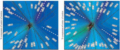
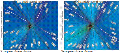
The descriptions of the results are given here with respect to the torsion axis location. This means that the torsion axis location approaching infinity along the chord-wise direction corresponds to a translation of the reference vane in the normal to the chord-wise direction. Similarly, a torsion axis location approaching infinity in the normal-to-chord direction is equivalent to a chord-wise bending. Thus, symmetry at infinity in the critical reduced frequency map about the reference vane is expected (Figs. 6-7). Furthermore, the stability prediction for bending-dominated modes become a complementary tool for clarification of the trends observed for the torsion-dominated modes.
As for freestanding blade cascades (Fig. 2b) the critical reduced frequency maps for the four-, five – and six-airfoil sectored vanes (Figs. 5-6) have two most stable and two most unstable regions. The directions of these regions are somewhat similar to the freestanding blades despite the vibration amplitude distribution between the airfoils in the sector (Figs. 6-7). The number of airfoils in the sector does not, in general, affect the directions of the two most stable and two most unstable regions (Figs. 6a-c and 7a-c). The two most stable regions are perpendicular to each other (see dashed line in Figs. 6-7). The first unstable region (which is also the largest of the two unstable regions found) is orientated almost normal to the pitch-wise direction of the cascade (dotted line 1). The second region of lower stability lies somewhere parallel to the throat line of the reference vane (dotted line 2). As expected, the aerodynamic damping level of the sectored vanes with the edge blade dominated (Figs. 7a-c) are higher than for the sectored vanes with the uniform vibration amplitude distribution (Figs. 6a-c). The critical reduced frequency values for the Case 2 amplitude distribution are varying between 0.03 and 0.17, while for the Case 1 those values are lying between 0.02 and 0.11.
![]()

(a) Four-airfoil sectored vane
(b) 
Five-airfoil sectored vane (b) Five-airfoil sectored vane
Figure 6. Case 1 vibration amplitude distil – Figure 7. Case 2 vibration amplitude distribution (far field domain) bution (far field domain)
This is still much lower than the freestanding blade cascade which has critical reduced frequency values between 0.05 and 0.5 (Fig. 2b).
 |
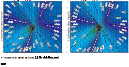
Soldier modes. Structural analysis shows that a vibration pattern with identical amplitude and zero inter-blade phase angle is a typical mode shape for a sectored vane cascade at low reduced frequencies. The critical reduced frequency maps for the four-, five – and six-airfoil sectored vanes for this so-called "soldier mode” are shown in Figures 8a, 8b and 8c, respectively.
As for a more general case of real sector mode shapes (far-held domain, Case 1 amplitude distribution, referred to Figs. 6a-c) a presence of the two most stable and two most unstable regions is observed. The absence of the out-phase motions of the blades within the sector, that characterizes the soldier modes, does not affect the directions of the second region of stability and the two instability regions (Figs. 8a-c). While the angle between the largest stable region and the pitch-wise direction of the cascade increases up to 45 degrees.
As expected, the sectored vanes undergoing solder modes become even more stable, in comparison to a more general case of real sector mode shapes, with the range of the critical reduced frequencies between 0.01-0.11.
Thus, also for bending-dominated modes the similarity between the main stability and instability directions for the four-, five – and six-airfoil sectored vanes are observed. The differences in the level of aerodynamic damping are defined by the number of the airfoils in the corresponding sectored vane. As expected, increasing the number of airfoils in sector from four to six increases the aerodynamic stability of the cascade.
6. Conclusions
A model for performing a stability analysis towards a reduced frequency and sector mode shape variation has been applied to a low-pressure turbine sectored vane. A parametrical study summarizing the effect of the reduced frequency and sector mode shape has been carried out varying the vibration amplitude distribution between the airfoils in sector as well as the number of airfoils in sector. The main assumption is that the ft>w is isentropic and two-dimensional. Critical reduced frequency maps have been provided for torsion – and bending – dominated sector mode shapes and the following conclusions have been drawn.
Even though the absolute value of the average aerodynamic work is rather different between four-, five – and six-airfoil sectors a high risk for instability still exists in the neighborhood of realistic reduced frequencies of modern low – pressure turbine (critical reduced frequency between 0.2 and 0.3 for torsion – dominated modes, between 0.01 and 0.05 for bending-dominated modes).
For the cases studied it is observed that the sectored vane displacement with the edge airfoils in the sector dominating provides the most unstable critical reduced frequency map.
Increasing the number of blades in the sector decreases the risk for a sectored vane to be unstable for uniform or internal blades dominated amplitude distributions. The stability of the sectored vane with edge blades dominated amplitude distribution is not affected much by the number of blades in the sector.
7. Future work
To generalize the findings, similar parametric studies should be performed for another sectored vane geometry and for other fbw conditions.
An extension from single to multiple frequency modes can be introduced in the present algorithm. It would take into account the mode coalescence, i. e. even though every single frequency mode by itself can be stable, their cross products may make the multiple frequency mode to be unstable.
Acknowledgments
The authors wish to thank GE Aircraft Engines for the provision of NOVAK (2D Version 6.0), for financial support and for the permission to publish the findings. Thanks also to the Swedish Energy Authority for partial financial support of the first author.
References
Whitehead, D. S., and Evans, D. H., 1992, “Flutter of grouped turbine blades”, 92-GT-227, ASME Gas Turbine and Aeroengine Congress and Exposition, Cologne, Germany.
Kahl, G., 1995, “Application of the time linearized Euler method to flitter and forced response calculations”, ASME paper 95-GT-123.
Chernysheva, O. V., Fransson, T. H., Kielb, R., E., and Barter, J., 2003, “Effect of sector mode shape variation on the aerodynamic stability of a low-pressure turbine sectored vane”, GT2003-38632, ASME/IGTI Turbo Expo, Atlanta, Georgia, USA.
Panovsky, J., and Kielb, R., E., 1998, “A design method to prevent low-pressure turbine blade flitter”, 98-GT-575, ASME Gas Turbine Conference and Exhibition, Stockholm, Sweden.
Tchernysheva, O. V., Fransson, T. H., Kielb, R., E., and Barter, J., 2001, “Comparative analysis of blade mode shape influence on flutter of two-dimensional turbine blades”, ISABE-2001-1243, XVISOABE Conference, Bangalore, India.
Lane, F., 1956, "System mode shapes in the flitter of compressor blade rows", Journal of the Aeronautical Science, Jan., pp. 54-66.
Holmes, D.,G., and, Chuang, H. A., 1991, “2D linearized harmonic Euler fbw analysis for flitter and forced response”, Unsteady Aerodynamics Aeroacoustics and Aeroelasticity of Turbomachines and Propellers, Springer Verlag, New York, pp. 213-230.


