FLIGHT AT HIGH LIFT CONDITIONS
It is frequently stated that the career Naval Aviator spends more than half his life “below a thousand feet and a hundred knots.” Regardless of the implications of such a statement, the thought does connote the relationship of minimum flying speeds and carrier aviation. Only in Naval Aviation is there such importance assigned to precision control of the aircraft at high lift conditions. Safe operation in carrier aviation demands precision control of the airplane at high lift conditions.
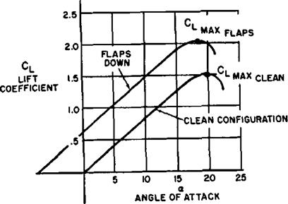
The aerodynamic lift characteristics of an airplane are portrayed by the curve of lift coefficient versus angle of attack. Such a curve is illustrated in figure 1.15 for a specific airplane in the clean and flap down configurations. A given aerodynamic configuration experiences increases in lift coefficient with increases in angle of attack until the maximum lift coefficient is obtained. A further increase in angle of attack produces stall and the lift coefficient then decreases. Since the maximum lift coefficient corresponds to the minimum speed available in flight, it is an important point of reference. The stall speed of the aircraft in level flight is related by the equation:
W
oS where
stall speed, knots TAS W= gross weight, lbs.
CLmax=airplane maximum lift coefficient 0=altitude density ratio T=wing area, sq. ft.
This equation illustrates the effect on stall speed of weight and wing area (or wing loading, WjS’), maximum lift coefficient, and altitude. If the stall speed is desired in EAS, the density ratio will be that for sea level (or= 1.000).
EFFECT OF WEIGHT. Modern configurations of airplanes are characterized by a large percent of the maximum gross weight being
fuel. Hence, the gross weight and stall speed of the airplane can vary considerably throughout the flight. The effect of only weight on stall speed can be expressed by a modified form of the stall speed equation where density ratio, CLmax, and wing area are held constant.
F
V wx
where
Vtl = stall speed corresponding to some gross weight, Wi
Vl2= stall speed corresponding to a different gross weight, W2
As an illustration of this equation, assume that a particular airplane has a stall speed of 100 knots at a gross weight of 10,000 lbs. The stall speeds of this same airplane at other gross weights would be:
Gross weight% lbs. Stall speed, knots EAS
10,0 100
11,000 lOOX^/-^—-=105
V 10,000
12,0 110
14,400 120
9,000 95
8,100 90
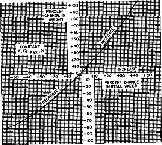
Figure 1.15 illustrates the effect of weight on stall speed on a percentage basis and will be valid for any airplane. Many specific conditions of flight are accomplished at certain fixed angles of attack and lift coefficients. The effect of weight on a percentage basis on the speeds for any specific lift coefficient and angle of attack is identical. Note that at small variations of weight, a rule of thumb may express the effect of weight on stall speed— “a 2 percent change in weight causes a 1 percent change in stall speed.”
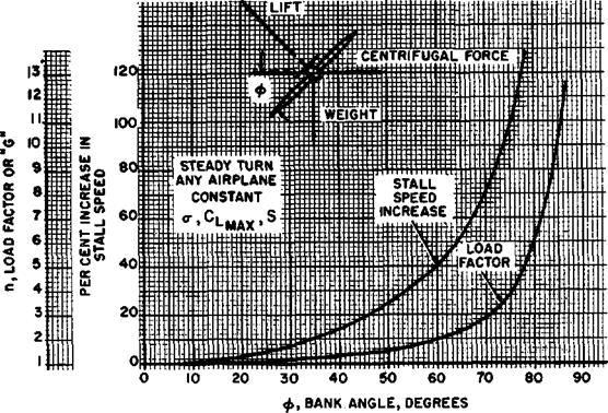
EFFECT OF MANEUVERING FLIGHT. Turning flight and maneuvers produce an effect on stall speed which is similar to the effect of weight. Inspection of the chart on figure 1.16 shows the forces acting on an airplane in a steady turn. Any steady turn requires that the vertical component of lift be equal to
|
EFFECT OF FLAPS
|
|
EFFECT OF WEIGHT ON STALL SPEED
Figure 1.15. Flight at High Lift Conditions |
weight of the airplane and the horizontal component of lift be equal to the centrifugal force. Thus, the aircraft in a steady turn develops a lift greater than weight and experiences increased stall speeds.
Trigonometric relationships allow determination of the effect of bank angle on stall speed and load factor. The load factor, », is the proportion between lift and weight and is determined by:
L
n=W
1
n=—– 7
COS Ф
where
»=load factor (or “G”) cos Ф = cosine of the bank angle, ф (phi)
Typical values of load factor determined by this relationship are:
ф_, 0° 15° 30° 43° 60° 75 5°
я. .1.00 1.035 1.154 1.414 2.000 4.000
The stall speed in a turn can be determined by:
У. ф=У, фі
where
У, Ф=stall speed at some bank angle ф V, = stall speed for wing level, lift-equal – weight flight
n = load factor corresponding to the bank angle
The percent increase in stall speed in a mm is shown on figure 1.16. Since this chart is predicated on a steady turn and constant CLmax, the figures are valid for any airplane. The chart shows that no appreciable change in load factor or stall speed occurs at bank angles less than 30°. Above 45° of bank the increase in load factor and stall speed is quite rapid. This fact emphasizes the need for avoiding steep turns at low airspeeds—a flight condition common to stall-spin accidents.
EFFECT OF HIGH LIFT DEVICES. The primary purpose of high lift devices (flaps, slots, slats, etc.) is to increase the CLm<a of the airplane and reduce the stall speed. The takeoff and landing speeds are consequently reduced. The effect of a typical high lift device is shown by the airplane lift curves of figure 1.15 and is summarized here:
|
Configuration |
“forC‘№ |
|
|
1.5 |
20° |
|
|
2.0 |
18.5° |
|
The principal effect of the extension of flaps is to increase the CLmax and reduce the angle of attack for any given lift coefficient. The increase in Czmax afforded by flap deflection reduces the stall speed in a certain proportion, the effect described by the equation:
where
V,/=stall speed with flaps down
V,=stall speed without flaps
Cbm=maximum lift coefficient of the clean configuration
CT, mf— maximum lift coefficient with flaps down
For example, assume the airplane described by the lift curves of figure 1.15 has a stall speed of 100 knots at the landing weight in the clean configuration. If the flaps are lowered the reduced stall speed is reduced to:
V.,= 100X^5
= 86.5 knots

|
|
 |
|
|
Thus, with the higher lift coefficient available, less dynamic pressure is required to provide the necessary lift.
Because of the stated variation of stall speed with CimaI) large changes in CLmax are necessary to produce significant changes in stall speed. This effect is illustrated by the graph in figure 1.16 and certain typical values are shown below:
Percent increase in Cj^………………….. 2 10 50 100 300
Percent reduction in stall speed.. 1 5 18 29 50
The contribution of the high lift devices must be considerable to cause large reduction in stall speed. The most elaborate combination of flaps, slots, slats, and boundary layer control throughout the span of the wing would be required to increase CLmgx by 300 percent. A common case is that of a typical propeller driven transport which experiences a 70 percent increase in CLma by full flap deflection. A typical single engine jet fighter with a thin swept wing obtains a 20 percent increase in Cim by full flap deflection. Thin airfoil sections with sweepback impose distinct limitations on the effectiveness of flaps and the 20 percent increase in CLmgx by flaps is a typical— if not high—value for such a configuration.
One factor common to maximum lift condition is the angle of attack and pressure distribution. The maximum lift coefficient of a particular wing configuration is obtained at one angle of attack and one pressure distribution. Weight, bank angle, load factor, density altitude, and airspeed have no direct effect on the stall angle of attack. This fact is sufficient justification for the use of angle of attack indicators and stall warning devices which sense pressure distribution on the wing. During flight maneuvers, landing approach, takeoff, turns, etc. the airplane will stall if the critical angle of attack is exceeded. The airspeed at which stall occurs will be determined by weight, load factor, and altitude but the stall angle of attack is unaffected. At any particular altitude, the indicated stall speed is a function of weight and load factor. An increase in altitude will produce a decrease in density and increase the true airspeed at stall. Also, an increase in altitude will alter compressibility and viscosity effects and, generally speaking, cause the indicated stall speed to increase. This particular consideration is usually significant only above altitudes of 20,000 ft.
Recovery from stall involves a very simple concept. Since stall is precipitated by an excessive angle of attack, the angle of attack must be decreased. This is a fundamental principle which is common to any airplane.
An airplane may be designed to be “stall – proof” simply by reducing the effectiveness of the elevators. If the elevators are not powerful enough to hold the airplane to high angles of attack, the airplane cannot be stalled in any condition of flight. Such a requirement for a tactical military airplane would seriously reduce performance. High lift coefficients near the maximum are required for high maneuverability and low landing and takeoff speeds. Hence, the Naval Aviator must appreciate the effect of the many variables affecting the stall speed and regard “attitude flying,” angle of attack indicators, and stall warning devices as techniques which allow more precise control of the airplane at high lift conditions.


