Flow Regimes
As can be seen in Fig. 2.1, density and pressure are rapidly decreasing with increasing altitude, whereas the temperature is more or less constant up to
![]()
 |
Kn=j. (2.16)
L
The characteristic length L can be a body length, a nose radius, a boundary-layer thickness, or the thickness of a shock wave, depending on the problem at hand.
Take for instance the thickness 5 of a laminar, incompressible flat-plate (Blasius) boundary layer [14]
as characteristic length. With Re^,x = p^u^x/p^ then
Kn = ^ = ^ /”’ .• (2.18)
5 cx
The Knudsen number can also be expressed in terms of the flight Mach number Ыж and the Reynolds number Re^,L, L being for instance the vehicle length:
Kn~ ■ . (2.20)
Re<x>,x
The Knudsen number is employed to distinguish approximately between flow regimes:
— continuum flow:
Kn < 0.01, (2.21)
— continuum flow with slip effects (slip flow and temperature jump at the body surface):
0.01 < Kn < 0.1, (2.22)
— disturbed free molecular flow (gas particles not only collide with the body surface, but also with each other):
0.1 < Kn < 10, (2.23)
— free molecular flow (gas particles collide only with the body surface, Newton limit [15]):
10 < Kn. (2.24)
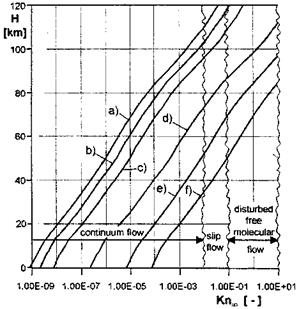
No sharp limits exist between the four flow regimes.[13] In Fig. 2.6 we show the Knudsen number Kn/L of some hypersonic flight vehicles and some vehicle components, with the characteristic length L taken as vehicle length or component diameter.
|
Fig. 2.6. Knudsen numbers Knas function of the altitude H for a) the SANGER lower stage, L ~ 80 m; b) the Space Shuttle Orbiter, L ~ 30 m; c) the X-38, L ~ 8 m; d) a nose cone, (D =) L ~ 0.3 m; e) a pitot gauge, (D=) L ~ 0.01 m; f) a measurement orifice, (D =) L ~ 0.001 m. |
Globally the lower stage of SANGER (case a), with a maximum flight altitude of approximately 35 km [16], the Space Shuttle Orbiter (case b), and also the X-38 (case c), remain fully in the continuum regime in the interesting altitude range below approximately 100 km. For the nose cone (case d) slip – flow effects can be expected above 75 km altitude. The pitot gauge (case e) is in the continuum regime only up to approximately 50 km altitude because of its small diameter, and likewise the measurement orifice (case f) only up to 35 km altitude.
Regarding the aerothermodynamic simulation means, we note that ground-test facilities are available for all flow regimes. However, in almost no case is a full simultaneous simulation possible of all relevant parameters for hypersonic flight.
Computational simulation for the continuum and for the slip-flow regime can be made with the methods of numerical aerothermodynamics. They include the Euler methods, the Navier-Stokes methods, the Reynolds-averaged Navier-Stokes (RANS) methods for turbulent flow, and the methods for the solution of the derivatives of the Navier-Stokes/RANS equations (boundary- layer methods, viscous shock-layer methods etc.).[14]
It is interesting to note that the Newton theory [15], which is exact for free molecular flow, can be used as inviscid computational tool in the continuum regime with sufficient accuracy down to M « 2 to 4, Section 6.7.
A major question that arises, is how shock waves, which are only a few mean-free paths thick, are treated in discrete numerical methods for the continuum regime. Shock waves, which as typical compressibility effects appear from transonic free-stream Mach numbers upwards, are found in the flow past all supersonic and hypersonic flight vehicles operating in this regime. We come back to this problem in Sub-Section 6.3.3.


