Our heavyweight helicopter equal in the world does not have
In Rostov started production of the most load-lifting rotary-wing car The Russian holding «Helicopt[...]

Everything about aircrafts and helicopters. News and events in aviation worldwide. Civil, transportation, military helicopters and airplanes.

Everything about aircrafts and helicopters. News and events in aviation worldwide. Civil, transportation, military helicopters and airplanes.

Everything about aircrafts and helicopters. News and events in aviation worldwide. Civil, transportation, military helicopters and airplanes.

Everything about aircrafts and helicopters. News and events in aviation worldwide. Civil, transportation, military helicopters and airplanes.


The elements of the thrust equation can be evaluated from a study of the flow field in Figure 1.1. In that figure, the three regions of interest have been numbered 0 for the region high above the rotor, 1 for the plane of the rotor, and 2 for the region far below the rotor in the fully developed rotor wake. The mass flow per second in the plane of the rotor is:
mjste = p vx A slugs/sec
where p is the density of the air in slugs/ft3, vx is the induced velocity, at the rotor plane, and A is the area of the rotor disc. The total change in velocity, Av, between region 0 and region 2 is:
Av = v2 — v0 ft/sec
Since far above the rotor the air has no velocity, the total change in velocity is:
Av = v2 ft/sec
Thus the expression for rotor thrust may be written:
T = p vxAv2 lb
The equation for thrust in this form is not very useful. Fortunately, a relationship between vx and v2 can be derived by equating the rate of energy dissipated at the rotor to the rate of energy imparted to the wake. Since the rotor and its wake make up a closed system, these two rates of energy must be equal. The energy per second dissipated by the rotor, Eg/sec, is:
Eg/sec = Force x Velocity
or
Eg/see = Tvx ft lb/sec
or
Eg/sec = pvA v2 ft lb/sec
The energy per second imparted to the wake, Ew/stc, is the total change in kinetic energy. Since there is no kinetic energy far above the rotor, the total change is the value found in the remote wake:
Ew/sec= і(/я2/sec) v
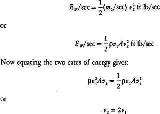 |
The mass flow per second in the remote wake, mjstc, is the same as the mass flow at the rotor, mjstc. This is a consequence of the Law of Continuity, which also applies to such things as syrup pouring from a pitcher. Once the flow is established, the amount of syrup reaching the pancake per second is the same as that leaving the lip of the pitcher even though the cross-section of the flow is larger at the top than at the bottom. The energy in the wake thus becomes:
That is, the induced velocity in the remote wake is twice the induced velocity at the rotor disc.
The equation for thrust becomes:
T=2pvA lb
and consequently the induced velocity in the plane of the rotor, vlt is:
The rotor thrust, T, divided by the disc area, A, is the disc loading, D. L., in pounds per square foot. The equation for the induced velocity may be written:
 |
||
For sea-level standard conditions, the density, p, is 0.002377 slugs per cubic foot, so that:
= 29 y/Dl. ft/sec
|
FIGURE 1.2 OH-6 Hovering in Dust |
Source: Hill, “A Promising Concept for the Joint Development of Military Intra-Theater and Commercial Inter-Urban VTOL Transports," 24th AHS Forum, 1968.
The example helicopter described in Appendix A has a design gross weight of 20,000 lb and a rotor radius of 30 ft. Assuming that the rotor thrust is equal to the gross weight, the disc loading is 7.1 lb/ft2, the velocity at the disc is 39 ft/sec, and the velocity in the remote wake is 78 ft/sec or 46 knots. For computations involving induced velocities produced by tandem-rotor helicopters in which one rotor overlaps the other, only the net projected area should be used in computing the disc loading. Similarly, with a coaxial helicopter, only the disc area of a single rotor should be used.