Longitudinal Control
In this section we discuss the longitudinal control of the vehicle from a static point of view. That is, we concern ourselves with how the equilibrium state of steady rectilinear flight is governed by the available controls. Basically there are two kinds of changes that can be made by the pilot or automatic control system—a change of propulsive thrust, or a change of configuration. Included in the latter are the operation of aerodynamic controls—elevators, wing flaps, spoilers, and horizontal tail rotation. Since the equilibrium state is dominated by the requirement Cm = 0, the most powerful controls are those that have the greatest effect on Cm.
Figure 2.14 shows that another theoretically possible way of changing the trim condition is to move the CG, which changes the value of a at which Cm = 0. Moving it forward reduces the trim a or CL, and hence produces an increase in the trim speed. This method was actually used by Lilienthal, a pioneer of aviation, in gliding flights during 1891/1896, in which he shifted his body to move the CG. It has the inherent disadvantage, apart from practical difficulties, of changing Cma at the same time, reducing the pitch stiffness and hence stability, when the trim speed is reduced.
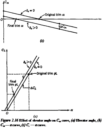
The longitudinal control now generally used is aerodynamic. A variable pitching moment is provided by moving the elevator, which may be all or part of the tail, or a trailing-edge flap in a tailless design. Deflection of the elevator through an angle 8e produces increments in both the Cm and CL of the airplane. The AC, caused by the elevator of aircraft with tails is small enough to be neglected for many purposes. This is not so for tailless aircraft, where the ACL due to elevators is usually significant. We shall assume that the lift and moment increments for both kinds of airplane are linear in 8e, which is a fair representation of the characteristics of typical controls at high Reynolds number. Therefore,
A CL = CLs8e (a)
CL = CL(a) + CLs8e (b)
ACm = Cms8e (c) ‘ ’
and Cm = Cm(a) + Cms8e (d)
where CL% = dCJd8e, C,„n> = dCJd8e, and CL(a), Cm(a) are the “basic” lift and moment when 8e = 0. The usual convention is to take down elevator as positive (Fig. 2.16a). This leads to positive CLs and negative Cms/ The deflection of the elevator
34 Chapter 2. Static Stability and Control—Part 1
^-Horizontal tail
c—1
 |
(a) ^
through a constant positive angle then shifts the Cm-a curve downward, without change of slope (Fig. 2.16b). At the same time the zero-lift angle of the airplane is slightly changed (Fig. 2.16c).
In the case of linear lift and moment, we have


