Methods
For this study two different methods were used. The first approach solves an adjoint problem to get an error estimate of a functional. This error estimate is used as sensor for adaptation. The second method is based on the local modification of the unstructured part of the mesh to increase the quality of the mesh. All computations were performed with the TAU solver from the DLR (Deutsches Zentrum fur Luft – und Raumfahrt).
2.1 Adjoint Error Estimation Method
The adjoint error estimation method uses a solution of an adjoint problem as sensor for an adaptation. The sensor is goal-oriented which means that for a specific goal function (e. g. CL, Cd or CMy) the sensitivity on the error of this goal-function is locally computed. Based on this error estimate the mesh is refined to improve the results with respect to the specified goal function.
The original sensor of [13] is based on an estimate for the goal function I on a globally refined mesh
Ih(UH – Ih(Uh) « {VH)TR{UH) (1)
by the adjoint у times the residuum R of the flow U, where the subscript h means results on the isotropically refined mesh, the superscript H denotes an extrapolation from the coarse to the fine mesh. So on the right hand side of (1) the adjoint у is computed on the original mesh and extrapolated to the fine mesh. The flow quantity
U is extrapolated to the fine mesh. After that the residuum is calculated on the fine mesh from this extrapolated vector.
To avoid the extrapolotion and the calculation of the residuum on the fine mesh a new sensor was developed by [2]. The idea of [2] is to assume that the major part of the discretization error comes from the dissipation error. The error estimate is then given by
<2>
The corrected value of the goal function is
+ JL). <3)
The related sensor for the adaptation is the absolute value of the local product
2.2 Mesh Manipulation
For optimizing a mesh, a quality measure for its elements has to be defined. Here the used quality measure based on the so-called mean ratio
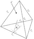
where Ai is the area, Vi the volume and lij the edge lengths of the element i (see figure 1a). Basically the measure is a ratio between the volume (3D) or area (2D) and the edge lengths.
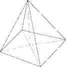
For three-dimensional cases this quality measure was extended to pyramids by splitting the pyramid into four tetrahedra by introducing a mid point on the basis of the pyramid (see figure 1b).
The implementation of the mean measure allows to use local anisotropic metrics. The modified metric can be helpful if more information about the flow e. g. a preliminary solution is available. In this case the orientation of the elements to the local flow is considered. Due to this new metric the edge lengths, area and volume are measured in the space of the new metric M. The size functions in the new metric are then given by
 |
 |
Fig. 1 (a) Nomenclature of variables on a tetrahedral element i. (b) Splitting of a pyramid into four tetrahedrons.
|
I’if = J(x/ – Xj)T • JC • (x/ – Xj), |
(6) |
|
|
А/ = yjdet {Ж |
(for 2D meshes), |
(7) |
|
V-g = |
(for 3D meshes). |
(8) |
For this study the metric was derived from the Hessian of the local Mach number
Malocal
^=^4—Ma/oca/. (9)
OXiOXj
To get a positive definite metric the Hessian was decomposed to its eigenvalues.
(h 0 0
H = R • 0 Я2 0 • RT. (10)
0 0 X3)
The new local metric is then defined by the absolute values of the eigenvalues
(ІЯ11 0 0
M = R • 0 ІЯ21 0 • RT (11)
V 0 0 ІА3)
To improve the quality of a three-dimensional mesh, four different methods are implemented to modify the unstructured:
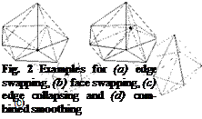
• edge swapping for up to 8 surrounding tetrahedrons [6, 10]
• face swapping [face to edge swap in 10]
• edge collapsing [9]
• combined smoothing [11, 1,4] with an optimizer for not continuously differentiable goal functions [5, 6, 3]
 |
|
 |
|
Each method modifies the mesh locally and acts on tetrahedrons. The combined smoothing and the edge collapsing were extended to allow modifications on points connected with pyramids. An example for each method is sketched in figure 2(a)- (d). For two-dimensional grids only edge swapping and the movement of nodes are implemented.
For pointwise optimization due to movement of a node, a goal function has to be defined which combines the quality of surrounding elements Si of a node i. Here the minimal quality
g (Si)= min q} (12)
jeSi
was used as goal function for the optimizer.
A modification of the grid is tried if the geometrical constraints allow a modification. Additionally the following demands have to be always fulfilled to accept a modification step:
• the minimal quality is larger than zero (to avoid inverted elements)
• the minimal quality is larger than the global minimal quality
• the goal function has to be improved (in the case of node movement)
• improve the mean quality (and therefore the global quality of the mesh)


