SHEAR CENTER
Consider a straight thin-walled beam of uniform cross section, which is subjected to a shearing force S as shown in Fig. 1.1. Let a set of orthogonal Cartesian coordinates xyz be chosen as shown in the figure, where
|
Fig. 1.1. Equilibrium of forces acting on an element of a thin-walled section. |
the z axis is parallel to the axis of the beam, and the x and у axes are the principal axes of the cross section. Let us assume that at any point in the cross section, the stress distribution over the wall thickness is uniform. It is convenient to introduce a curvilinear coordinate s along the circumferential direction of the cross section, and to speak of the “shear flow,” meaning the shearing force per unit of circumference
q = rt (1)
where r is the shearing stress, and t is the thickness of the wall. The equation of equilibrium of the forces in the axial direction acting on a small element of area ds dz is, according to the diagram on the right-hand side of Fig. 1.1, where oz denotes the axial stress :
(az + dz) t ds — ozt ds + | r + ) t dz — rt dz = 0 (2)
Passing to the limit ds, dz -> 0, one obtains
or, multiplying by the thickness t, if it is constant,
 |
Thus the shear flow q depends on the rate of change of the axial stress az. A few simple cases will be considered below.
(a) Flat Shear Webs. A flat “shear web” is one that is subjected to pure shear; i. e., it is defined by the condition az = 0. Such a web is approximated by the one shown in Fig. 1.2. In this case, Eq. 4 implies that
|
q — const |
(5) |
|
The constant is easily evaluated from statics: |
|
|
S |
|
|
q = h |
(6) |
where S is the total shear force over a section, and h is the height of the web»
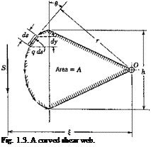
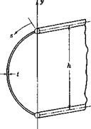
(b) Curved Shear Webs. According to Eq. 4, the condition q = const prevails also for a “curved shear web,” over which az = 0. As shown in Fig. 1.3, the shear flow follows the curvature of the cross section. The resultant force in the у direction is
S = J q cos в ds (7)
where в is the angle between the vector of the shear flow q and the у axis, and the integration is taken over the entire section. Obviously
S — § q dy — q h j (8)
(9)
![]()
which is the same as Eq. 5. The shear flow is equal to the total shear force divided by the height of the beam.
 |
 |
It is important to find the location of the resultant shear. For this purpose the moment about a point О in the plane of the cross section
produced by the shear flow may be computed. Let r be the perpendicular distance from 0 to the tangent at s where q acts. From Fig. 1.3 the moment about 0 is
M0 = $qrds (10)
Since q is a constant, this may be written as
M0 = q §r ds = 2qA (11)
where A is the area of a sector enclosed between the cm /ed shear web and two radius vectors with origin at 0 as shown in the figure. But this moment is also equal to the resultant shear S times its moment arm £ about the origin 0,
M0 = S£
It can be easily verified that the spatial location of the line of action of the resultant shear is independent of the location of the origin 0.
The web of a two-flange type of beam approximates in practice the
shear web described above. Such a beam can transmit a shear force, but only if the forge is applied at the location specified by Eq. 12 and parallel to the plane of the two flanges, as shown in Fig. 1.3. If it is applied along any other line of action, it will cause an unbalanced twisting moment that the beam alone cannot resist.
(c) Open Thin-Walled Sections. In general, the axial stress az does not vanish when the beam is subjected to a transverse loading. In many cases, however, it is sufficiently accurate to use the elementary beam formula for a bending moment M due to the transverse loading
![]()
![]() My I
My I
where у is the distance from the neutral plane, provided that the у axis is a principal axis of the cross section, and that the shear load vector is parallel to the у axis. Hence,
![]() Эогг _ у dM у
Эогг _ у dM у
?z I dz I
in accordance with Eq. 3 of § 1.1. If we assume again that the shearing stress is uniformly distributed over the wall thickness, the shear flow is — obtained from Eq. 4 by an integration:
where q0 is the value of q at j0. Using Eq. 14, one obtains
S P
 |
q = % – 7 Je2/? ds (15)
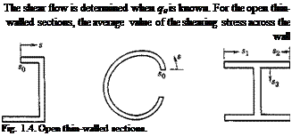
thickness vanishes at the ends of the section, in accordance with St. Venant’s theory of torsion. Hence, if s0 is taken as one of the ends, then q0 — 0. This is illustrated in Fig. 1.4.
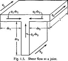
In the last case of Fig. 1.4, there is a junction where three members meet. Let qx, q2, q3 be the shear flow toward the junction in the three members, respectively; then a condition of equilibrium is
This can be seen from the free-body diagram of a small element at the junction as shown in Fig. 1.5. Equation 16 represents the condition of equilibrium of the forces in the axial direction.
|
|
For a multi-flanged beam, the material concentrated at the flanges resists the bending moment (Fig. 1.6). Equation 15 can be modified to give the change of shear flow across each of the flanges. Let ДA be the
|
|
area of a flange, then the difference of q on the two sides of the flange is
Aq = — ~yAA (17)
The equations given above are sufficient to determine the shear flow in any open thin-walled section. When q is known, the resultant force is
given by Eq. 7, and the resultant moment about the origin О is given by Eq. 10. The location of the line of action of the resultant shear is therefore at a distance £ from the origin:
![]() (18)
(18)
where the symbols r, s, and у have the same meaning as shown in Fig. 1.3, and the integral is taken over the entire cross section. The shear flow q is, in general, a function of s and cannot be taken outside of the integral.
Similar calculation can be made if a shear acts in the direction of the other principal axis of the beam cross section. The distance from the origin, г], of the line of action of the resultant shear which is parallel to x axis, can be determined by an expression similar to Eq. 18. The intersection of these two lines of action, the point with coordinates £, r referred to a set of centroidal principal axis, is called the shear center of the cross section. Since an arbitrary shear load can be resolved into components parallel to the two principal directions, it becomes evident that, if a shear vector acts through the shear center of the cross section, the bending stress distribution will be given by the elementary beam formula, and no twisting of the beam will occur. This is the significance of the shear center.
If the resultant shear does not pass through the shear center, it can be resolved into a shear of equal magnitude that does pass through the shear center and cause torsionless bending, and a couple that will cause twisting.
(d) Closed Thin-Walled Sections and Solid Sections. The equations derived in the previous paragraph apply as well to closed thin-walled sections, except that it is now no longer evident that there exists a point s0 at which q0 vanishes. The exact values of q depend on the line of action of the resultant shear force.
It is convenient to define the shear center as a point through’ which acts a shear force that will produce a “pure” or “torsion-free” bending. The beam subjected to a shear force that acts through the shear center will be “torsion-free.” A shear force that acts in a line that does not pass through the shear center will cause both bending and torsion.
The analytical formulation of the above definition depends, however, on the precise meaning of the term “pure bending” or “torsion-free bending.” Based on the classical theories of bending and torsion, several different but equally convincing definitions have been proposed for “pure bending.” A detailed discussion is presented in Appendix I, which covers also solid sections and thick-walled sections. For a given definition of the term “pure bending,” a corresponding location of the shear center can be computed. Fortunately, shear-center positions of airplane structures
based on various definitions differ very little from each other, and in practical applications any one of these definitions may be used.
It may be noted that the shear-center locations calculated in previous paragraphs under cases b and c are in agreement with the definition just given. No ambiguity exists for the concept of torsion-free bending in an open thin-walled section. This clear-cut feature is a result of the assumption that the shearing stress is distributed uniformly over the thickness of the section.


