Aerofoil characteristics
Lift coefficient: incidence
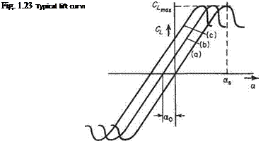
This variation is illustrated in Fig. 1.23 for a two-dimensional (infinite span) wing. Considering first the full curve (a) which is for a moderately thick (13%) section of
zero camber, it is seen to consist of a straight line passing through the origin, curving over at the higher values of Cl, reaching a maximum value of Сгшд at an incidence of as, known as the stalling point. After the stalling point, the lift coefficient decreases, tending to level off at some lower value for higher incidences. The slope of the straight portion of the curve is called the two-dimensional lift-curve slope, (dCi/da)^ or floe. Its theoretical value for a thin section (strictly a curved or flat plate) is 27Г per radian (see Section 4.4.1). For a section of finite thickness in air, a more accurate empirical value is
![]()
 |
(1.66)
The value of Сis a very important characteristic of the aerofoil since it determines the minimum speed at which an aeroplane can fly. A typical value for the type of aerofoil section mentioned is about 1.5. The corresponding value of as would be around 18°.
Curves (b) and (c) in Fig. 1.23 are for sections that have the same thickness distribution but that are cambered, (c) being more cambered than (b). The effect of camber is merely to reduce the incidence at which a given lift coefficient is produced, i. e. to shift the whole lift curve somewhat to the left, with negligible change in the value of the lift-curve slope, or in the shape of the curve. This shift of the curve is measured by the incidence at which the lift coefficient is zero. This is the no-lift incidence, denoted by Qo, and a typical value is —3°. The same reduction occurs in as. Thus a cambered section has the same value of as does its thickness distribution, but this occurs at a smaller incidence.
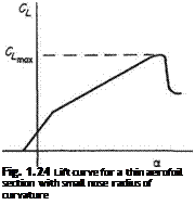
Modern, thin, sharp-nosed sections display a slightly different characteristic to the above, as shown in Fig. 1.24. In this case, the lift curve has two approximately straight portions, of different slopes. The slope of the lower portion is almost the same as that for a thicker section but, at a moderate incidence, the slope takes a different, smaller value, leading to a smaller value of C^, typically of the order of unity. This change in the lift-curve slope is due to a change in the type of flow near the nose of the aerofoil.
 |
Effect of aspect ratio on the CL a curve
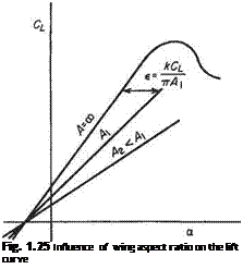
The induced angle of incidence є is given by
where A is the aspect ratio and thus
![]() «ос = a –
«ос = a –
Considering a number of wings of the same symmetrical section but of different aspect ratios the above expression leads to a family of Cl, a curves, as in Fig. 1.25, since the actual lift coefficient at a given section of the wing is equal to the lift coefficient for a two-dimensional wing at an incidence of a^.
 |
For highly swept wings of very low aspect ratio (less than 3 or so), the lift curve slope becomes very small, leading to values of С^и of about 1.0, occurring at stalling incidences of around 45°. This is reflected in the extreme nose-up landing attitudes of many aircraft designed with wings of this description.


