Control Force to Trim
The importance of control forces in relation to handling qualities has already been emphasized in previous sections, and the many options available to designers of powered control systems has been noted. Cockpit devices can of course be designed to produce more or less any desired synthetic feel on the primary flight controls. It is nevertheless both instructive and necessary to be able to calculate the control forces that will be present in the case of natural feel, or when a simple power assist is present. A case in point is the elevator force required to trim the airplane, and how it varies with flight speed.
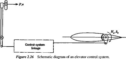
Figure 2.26 is a schematic representation of a reversible control system. The box denoted “control system linkage” represents any assemblage of levers, rods, pulleys,
|
|
cables, and power-boost elements that comprise a general control system. We assume that the elements of the linkage and the structure to which it is attached are ideally rigid, so that no strain energy is stored in them, and we neglect friction. The system then has one degree of freedom. P is the force applied by the pilot, (positive to the rear) s is the displacement of the hand grip, and the work done by the power boost system is Wb. Considering a small quasistatic displacement from equilibrium (i. e., no kinetic energy appears in the control system), conservation of energy gives
Pds + dWb + HedSe = 0 (2.8,1)
dWh d8e
Now the nature of ratio or power boost controls is such that dWJds is proportional to P or He. Hence we can write
P = (Gl – G2)He (2.8,2)
d8e
where G, =————— >0, the elevator gearing ( rad/ft or rad/m)
ds
dWJds
and G2 = ——— , the boost gearing (ft orm )
He
(2.8,2) is now rewritten as
P = GHe (2.8,3)
where G = G, — G2. For fixed Gu i. e., for a given movement of the control surface to result from a given displacement of the pilot’s control, then the introduction of power boost is seen to reduce G and hence P. G may be designed to be constant over the whole range of 8e, or it may, by the use of special linkages and power systems, be made variable in almost any desired manner.
Introduction of the hinge-moment coefficient gives the expression for P as
P = GCheSecepV2 (2.8,4)
and the variation of P with flight speed depends on both V2 and on how Che varies with speed.
The value of Che at trim for arbitrary tab angle is given by
Che = Cheo + Che<alnm + h28ernrn + b3S, (2.8,5)
(2.8,5) in combination with (2.7,1) yields
= b3(8, – 8taJ (2.8,6)
i.
 |
e., the hinge moment is zero when 5, = 5,tnm as expected, and linearly proportional to the difference. From (2.7,2) then the hinge moment is
|
w Ipv1 |
Lift equals the weight in horizontal flight, so that
where w = W/S is the wing loading. When (2.8,7 and 8) are substituted into (2.8,4) the result obtained is
P = A + BpV2 (2.8,9)
where
a’b2
A = – GSecew ~(h~ K) det
 M, + Cheo + (CheCLSe – b2CLa)
 |
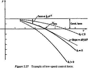
The typical parabolic variation of P with V when the aerodynamic coefficients are all constant, is shown in Fig. 2.27. The following conclusions may be drawn.
1. Other things remaining equal, P Sece, i. e., to the cube of the airplane size. This indicates a very rapid increase in control force with size.
2. P is directly proportional to the gearing G.
3. The CG position only affects the constant term (apart from a second-order influence on Cms). A forward movement of the CG produces an upward translation of the curve.
4. The weight of the airplane enters only through the wing loading, a quantity that tends to be constant for airplanes serving a given function, regardless of weight. An increase in wing loading has the same effect as a forward shift of the CG.
5. The part of P that varies with pV2 decreases with height, and increases as the speed squared.
6. Of the terms contained in B, none can be said in general to be negligible. All of them are “built-in” constants except for Sr
7. The effect of the trim tab is to change the coefficient of pV2, and hence the curvature of the parabola in Fig. 2.27. Thus it controls the intercept of the curve with the V axis. This intercept is denoted Vtrim; it is the speed for zero control force.


