Flutter Suppression by Changing Direction of Blade Oscillation
The control by changing the oscillation direction of blade was numerically analyzed. The control method is thought possible by application of a kind of shape memory alloy.
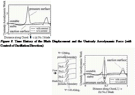
To study the effectiveness of the control, the case in which all blades were forced to oscillate were analyzed in 4 fbw channels with 90 degrees of inter blade phase angle as shown in Fig. 8. The oscillation directions of No.1 and No.3 blades were set to be 143.42 degrees, while those of No.2 and No.4 blades were 120 degrees. Figure 8 shows the chordwise unsteady aerodynamic work distribution on the blade surface. Solid line is the result of the case with control, while dotted line is that of the case without control. Figure 8(a) is the result of No.1 blade (Ф =143.42 deg.), and Fig. 8(b) is that of No.2 blade (Ф =120 deg.). From Fig. 8(a), it is seen that the result of the controlled case is almost the same as that of the case without control for No. 1 blade. For the No. 2 blade, however, the peak at 50% chord position on the pressure surface changes from positive one to negative one by the control as shown in Fig. 8(b). Alteration of the blade oscillation direction should change the movement of passage shock, and the induced unsteady aerodynamic work should thereby be changed into, possibly, stable direction.
Based on the previous results, the control method of changing oscillation direction of blade was analyzed by the fbw-structure coupled method. Initial velocity of 0.01Cw (C:chord length, w:angular frequency of blade) was given to No.1 blade, and -0.01Cw to No.3 blade. No.2 and No.4 blade were set
|
Figure 8. Variation of Unsteady Aerodynamic Work Distribution on the Blade Surface due to the Direction of Oscillation |

stationary at the initial state. The angle of blade motion, Ф, of all blades was initially 120 degrees. The angle Ф of No.1 and No.3 blades was impulsively changed to 143.42 degrees from 120 degrees at the time when the displacement of the blades started to increase.
Figure 9 shows the time history of the displacements of No.1 and No.2 blades as well as the unsteady aerodynamic force on these blades. The dotted line indicates the result when Ф of all blades are kept 120 degrees for comparison. As shown in Fig.9, the increase in displacement was effectively suppressed by changing oscillation direction. The phase of the unsteady aerodynamic force is observed to delay compared with that of the blade displacement after the start of the control. In this situation, the unsteady aerodynamic force acts as a damping force on the blade. As for the No.2 blade, the result corresponds to that of the previous result shown in Fig. 8. The displacement of No. 1 blade was decreased probably because of the inflience of the decrease in the displacement of No.2 blade.


