Generation of Lift
Figure 3.12 is a qualitative description of the flow field and its resultant forces on the aerofoil. The result of skin friction is the drag force, shown in Figure 3.12b. The lift is normal to the flow.
Section 3.5 explains that a typical aerofoil has an upper surface more curved than the lower surface, which is represented by the camber of the aerofoil. Even for a symmetrical aerofoil, the increase in the angle of attack increases the velocity at the upper surface and the aerofoil approaches stall, a phenomenon described in Section 3.10.
Figure 3.13a shows the pressure field around the aerofoil. The pressure at every point is given as the pressure coefficient distribution, as shown in Figure 3.13b. The upper surface has lower pressure, which can be seen as a negative distribution. In addition, cambered aerofoils have moments that are not shown in the figure.
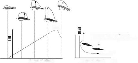
Figure 3.14a shows the typical test results of an aerofoil as plotted against a variation of the angle of attack, a. Initially, the variation is linear; then, at about 10 deg a, it starts to deviate and reaches maximum Cl (Cimax at amax). Past amax, the Cl drops rapidly – if not drastically – when stall is reached. Stalling starts at reaching amax. These graphs show aerofoil characteristics. Figure 3.14b depicts the corresponding distribution of the pressure coefficient Cp at an angle of attack of 15 deg.
Deflection of either the control surface or a change in the angle of attack will alter the pressure distribution. The positive Y-direction has negative pressure on the upper surface. The area between the graphs of the upper and lower surface Cp distribution is the lift generated for the unit span of this aerofoil.
Figure 3.15 shows flow physics around the aerofoil. At the LE, the streamlines move apart: One side negotiates the higher camber of the upper surface and the other side negotiates the lower surface. The higher curvature at the upper surface generates a faster flow than the lower surface. They have different velocities when they meet at the trailing edge, creating a vortex sheet along the span. The phenomenon can be decomposed into a set of straight streamlines representing the
 |
 free streamflow condition and a set of circulatory streamlines of a strength that matches the flow around the aerofoil. The circulatory flow is known as the circulation of the aerofoil. The concept of circulation provides a useful mathematical formulation to represent lift. Circular flow is generated by the effect of the aerofoil camber, which gives higher velocity over the upper wing surface. The directions of the circles show the increase in velocity at the top and the decrease at the bottom, simulating velocity distribution over the aerofoil.
The flow over an aerofoil develops a lift per unit span of l = pUr (see other textbooks for the derivation). Computation of circulation Г is not easy. This book uses accurate experimental results to obtain the lift.
The center of pressure, cp, is the point through which the resultant force of the pressure field around the body acts. For an aerofoil, it moves forward as the angle of attack is increased until stall occurs as a degenerate case (Figure 3.16).
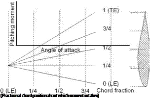
The aerodynamic center, ac, is concerned with moments about a point, typically on the chord line (Figures 3.17). The relationship between the moment and the angle of attack depends on the approximate point at which the moment is taken. However, at the quarter-chord point (there could be minor variations among aerofoils but they
Stall
Locus of Cp moving aft
with reduced angle of attack
toward ТЕ
Figure 3.16. Movement of center of pressure with change in lift
Figure 3.17. Aerodynamic center – invariant near quarter-chord
 are ignored in this book), it is noticed that the moment is invariant to the angle of attack until stall occurs. This point at the quarter chord is called the ac, which is a natural reference point through which all forces and moments are defined to act. The ac offers much useful information that is discussed later.
The higher the positive camber, the more lift is generated for a given angle of attack; however, this leads to a greater nose-down moment. To counter this nose – down moment, conventional aircraft have a horizontal tail with the negative camber supported by an elevator. For tailless aircraft (e. g., delta wing designs in which the horizontal tail merges with the wing), the trailing edge is given a negative camber as a “reflex.” This balancing is known as trimming and it is associated with the type of drag known as trim drag. Aerofoil selection is then a compromise between having good lift characteristics and a low moment.


