HIGH LIFT DEVICES
There are many different types of high lift devices used to increase the maximum lift coefficient for low speed flight. The high lift devices applied to the trailing edge of a section consist of a flap which is usually 15 to 25 percent of the chord. The deflection of a flap produces the effect of a large amount of camber added well aft on the chord. The principal types of flaps are shown applied to a basic section of airfoil. The effect of a 30° deflection of a 25 percent chord flap is shown on the lift and drag curves of figure 1.17.
|
|
|
|
|
|
|
EFFECT ON SECTION-LIFT AND DRAG
CHARACTERISTICS OF A 25% CHORD
FLAP DEFLECTED 30°
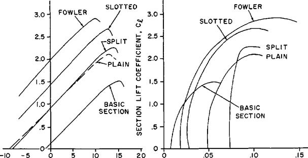
SECTION ANGLE OF ATTACK SECTION DRAG COEFFICIENT
o0l DEGREES Cd
Figure 1.17. Flap Configurations
Revised Jonuory 1965
The plain flap shown in figure 1.17 is a simple hinged portion of the trailing edge. The effect of the camber added well aft on the chord causes a significant increase in ctmai. In addition, the zero lift angle changes to a more negative value and the drag increases greatly. The split flap shown in figure 1.17 consist of plate deflected from the lower surface of the section and produces a slightly greater change in Ci than the plain flap. However, a much larger change in drag results from the great turbulent wake produced by this type flap. The greater drag may not be such a disadvantage when it is realized that it may be advantageous to accomplish steeper landing approaches over obstacles or require higher power from the engine during approach (to minimize engine acceleration time for waveoff).
The slotted flap is similar to the plain flap but the gap between the main section and flap leading edge is given specific contours. High energy air from the lower surface is ducted to the flap upper surface. The high energy air from the slot accelerates the upper surface boundary layer and delays airflow separation to some higher lift coefficient. The slotted flap can cause much greater increases in clmi than the plain or split flap and section drags are much lower.
The Fowler flap arrangement is similar to the slotted flap. The difference is that the deflected flap segment is moved aft along a set of tracks which increases the chord and effects an increase in wing area. The Fowler flap is characterized by large increases in clmax with minimum changes in drag. .
One additional factor requiring consideration in a comparison of flap types is the aerodynamic twisting moments caused by the flap. Positive camber produces a nose down twisting moment—especially great when large camber is used well aft on the chord (an obvious implication is that flaps are not practical on a flying wing or tailless airplane). The deflection of a flap causes large nose down moments which create important twisting loads on the structure and pitching moments that must be controlled with the horizontal tail. Unfortunately, the flap types producing the greatest increases in clmax usually cause the greatest twisting moments. The Fowler flap causes the greatest change in twisting moment while the split flap causes the least. This factor-along with mechanical complexity of the installation—may complicate the choice of a flap configuration.
The effectiveness of flaps on a wing configuration depend on many different factors. One important factor is the amount of the wing area affected by the flaps. Since a certain amount of the span is reserved for ailerons, the actual wing maximum lift properties will be less than that of the flapped two-dimensional section. If the basic wing has a low thickness, any type of flap will be less effective than on a wing of greater thickness. Sweepback of the wing can cause an additional significant reduction in the effectiveness of flaps.
High lift devices applied to the leading edge of a section consist of slots, slats, and small amounts of local camber. The fixed slot in a wing conducts flow of high energy air into the boundary layer on the upper surface and delays airflow separation to some higher angle of attack and lift coefficient. Since the slot alone effects no change in camber, the higher maximum lift coefficient will be obtained at a higher angle of attack, i. e., the slot simply delays stall to a higher angle of attack. An automatic slot arrangement consists of a leading edge segment (slat) which is free to move on tracks. At low йngles of attack the slat is held flush against the leading edge by the high positive local pressures. When the section is at high angles of attack, the high local suction pressures at the leading edge create a chordwise force forward to actuate the slat. The slot formed then allows the section to continue to a higher angle of attack and produce а сгтах greater than that of the
|
|
|
|
|
|

BOUNDARY LAYER CONTROL
BY FLAP AUGMENTATION
SECTION ANGLE OF ATTACK SECTION ANGLE OF ATTACK
a0, DEGREES a0, DEGREES
Figure 1.13. Effect of Slots and Boundary Layer Control
basic section. The effect of a fixed slot on the lift characteristics is shown in figure 1.18.
Slots and slats can produce significant increases in cXmu but the increased angle of attack for maximum lift can be a disadvantage. If slots were the only high lift device on the wing, the high take off and landing angles of attack may complicate the design of the landing gear. For this reason slots or slats are usually used in conjunction with flaps since the flaps provide reduction in the maximum lift angle of attack. The use of a slot has two important advantages: there is only a negligible change in the pitching moment due to the slot and no significant change in section drag at low angles of attack. In fact, the slotted section will have less drag than the basic section near the maximum lift angle for the basic section.
The slot-slat device finds great application in modern airplane configurations. The tailless airplane configuration can utilize only the high lift devices which have negligible effect on the pitching moments. The slot and slat are often used to increase the cimai in high speed flight when compressibility effects are considerable. The small change in twisting moment is a favorable feature for any high lift device to be used at high speed. Leading edge high lift devices are more effective on the highly swept wing than trailing edge flaps since slats are quite powerful in controlling the flow pattern. Small amounts of local camber added to the leading edge as a high lift device is most effective on wings of very low thickness and sharp leading edges. Most usually the slope of the leading edge high lift device is used to control the spanwise lift distribution on the wing.
‘Boundary laytr control devices are additional means of increasing the maximum lift coefficient of a section. The thin layer of airflow adjacent to the surface of an airfoil shows reduced local velocities from the effect of skin friction. When at high angles of attack this boundary layer on the upper surface tends to stagnate and come to a stop. If this happens the airflow will separate from the surface and stall occurs. Boundary layer control for high lift applications features various devices to maintain high velocity in the boundary layer to allay separation of the airflow. This control of the boundary layer kinetic energy can be accomplished in two ways. One method is the application of a suction through ports to draw off low energy boundary layer and replace it with high velocity air from outside the boundary layer. The effect of surface suction boundary layer control on lift characteristics is typified by figure 1.18. Increasing surface suction produces greater maximum lift coefficients which occur at higher angles of attack. The effect is similar to that of a slot because the slot is essentially a boundary layer control device ducting high energy air to the upper surface.
Another method of boundary layer control is accomplished by injecting a high speed jet of air into the boundary layer. This method produces essentially the same results as the suction method and is the more practical installation. The suction type BLC requires the installation of a separate pump while the ‘ ‘blown’ ’ BLC system can utilize the high pressure source of a jet engine compressor. The typical installation of a high pressure BLC system would be the augmentation of a deflected flap. Since any boundary layer control tends to increase the angle of attack for maximum lift, it is important to combine the boundary layer control with flaps since the flap deflection tends to reduce the angle of attack for maximum lift.
OPERATION OF HIGH LIFT DEVICES. The management of the high lift devices on an airplane is an important factor in flying operations, The devices which are actuated automatically—such as automatic slats and slots— are usually of little concern and cause little complication since relatively small changes in drag and pitching moments take place. However, the flaps must be properly managed by the pilot to take advantage of the capability
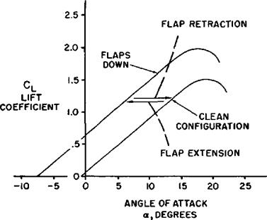
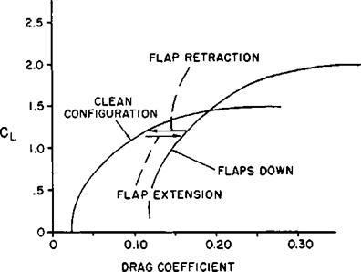
Figure 1.19. Effect of Flaps on Airplane Characteristics
of such a device. To illustrate a few principles of flap management, figure 1.19 presents the lift and drag curves of a typical airplane in the clean and flap down configurations.
In order to appreciate some of the factors involved in flap management, assume that the airplane has just taken off and the flaps are extended. The pilot should not completely retract the flaps until the airplane has sufficient speed. If the flaps are retracted prematurely at insufficient airspeed, maximum lift coefficient of the clean configuration may not be able to support the airplane and the airplane will sink or stall. Of course, this same factor must be considered for intermediate flap positions between fully retracted and fully extended. Assume that the airplane is allowed to gain speed and reduce the flight lift coefficient to the point of flap retraction indicated on figure 1.19. As the configuration is altered from the "cluttered” to the clean configuration, three important changes take place:
(1) The reduction in camber by flap retraction changes the wing pitching moment and—for the majority of airplanes—requires retrimming to balance the nose up moment change. Some airplanes feature an automatic retrimming which is programmed with flap deflection.
(2) The retraction of flaps shown on figure 1.19 causes a reduction of drag coefficient at that lift coefficient. This drag reduction improves the acceleration of the airplane.
(3) The retraction of flaps requires an increase in angle of attack to maintain the same lift coefficient. Thus, if airplane acceleration is low through the flap retraction speed range, angle of attack must be increased to prevent the airplane from sinking. This situation is typical after takeoff when gross weight, density altitude, and temperature are high. However, some aircraft have such high acceleration through the flap retraction speed that the rapid gain in airspeed requires much less noticeable attitude change.
When the flaps are lowered for landing essentially the same items must be considered. Extending the flaps will cause these changes to take place:
(1) Lowering the flaps requires retrimming to balance the nose down moment change.
(2) The increase in drag requires a higher power setting to maintain airspeed and altitude.
(3) The angle of attack required to produce the same lift coefficient is less, e. g., flap extension tends to cause the airplane to "balloon.”
An additional factor which must be considered when rapidly accelerating after takeoff, or when lowering the flaps for landing, is the limit airspeed for flap extension. Excessive airspeeds in the flap down configuration may cause structural damage.
In many aircraft the effect of intermediate flap deflection is of primary importance in certain critical operating conditions. Small initial deflections of the flap cause noticeable changes in Cwithout large changes in drag coefficient. This feature is especially true of the airplane equipped with slotted or Fowler flaps (refer to fig. 1.17). Large flap deflections past 30° to 35° do not create the same rate of change of Cl^ but do cause greater changes in CD■ A fact true of most airplanes is that the first 50 percent of flap deflection causes more than half of the total change in Cl^ and the last 50 percent of flap deflection causes more than half of the total change in CD.
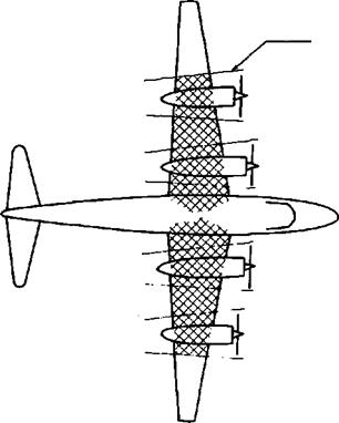
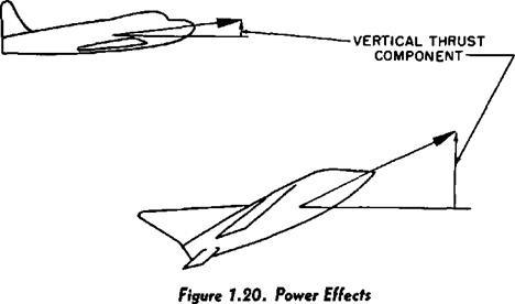
The effect of power on the stall speed of an airplane is determined by many factors. The most important factors affecting this relationship are powerplant type (prop or jet), thrust- to-weight ratio, and inclination of the thrust vector at maximum lift. The effect of the propeller is illustrated in figure 1.20. The slipstream velocity behind the propeller is different from the free stream velocity depending on the thrust developed. Thus, when the propeller driven airplane is at low airspeeds
|
NAVWEPS 00-80T-80
BASIC aerodynamics
and high power, the dynamic pressure in the shaded area can be much greater than the free stream and this causes considerably greater lift than at zero thrust. At high power conditions the induced flow also causes an effect similar to boundary layer control and increases the maximum lift angle of attack. The typical four-engine propeller driven airplane may have 60 to 80 percent of the wing area affected by the induced flow and power effects on stall speeds may be considerable. Also, the lift of the airplane at a given angle of attack and airspeed will be greatly affected. Suppose the airplane shown is in the process of landing flare from a power-on approach. If there is a sharp, sudden reduction of power, the airplane may drop suddenly because of the reduced lift.
The typical jet aircraft docs not experience the induced flow velocities encountered in propeller driven airplanes, thus the only significant factor is the vertical component of thrust. Since this vertical component contributes to supporting the airplane, less aerodynamic lift is required to hold the airplane in flight. If the thrust is small and the thrust inclination is slight at maximum lift angle, only negligible changes in stall speed will result. On the other hand, if the thrust is very great and is given a large inclination at maximum lift angle, the effect on stall speed can be very large. One important relationship remains—since there is very little induced flow from the jet, the angle of attack at stall is essentially the same power-on or power-off.


