Induced drag
Section 5.5 below should also be referred to. Consider what is happening at some point у along the wing span (Fig. 1.21). Each of the trailing vortices produces a downwards component of velocity, w, at y, known as the downwash or induced velocity (see Section 5.5.1). This causes the flow over that section of the wing to be inclined slightly downwards from the direction of the undisturbed stream V (Fig. 1.22) by the angle e, the induced angle of incidence or downwash angle. The local flow is also at a slightly different speed, q.
If the angle between the aerofoil chord line and the direction of the undisturbed stream, the geometric angle of incidence, is a, it is seen that the angle between the chord line and the actual flow at that section of the wing is equal to а—e, and this is called the effective incidence a^. It is this effective incidence that determines the lift coefficient at that section of the wing, and thus the wing is lifting less strongly than the geometric incidence would suggest. Since the circulation and therefore w and є increase with lift coefficient, it follows that the lift of a three-dimensional wing increases less rapidly with incidence than does that for a two-dimensional wing, which has no trailing vortices.
Now the circulation round this section of the wing will have a value Г appropriate to «ос, and the lift force corresponding to this circulation will be pqT per unit length, acting perpendicular to the direction of q as shown, i. e. inclined backwards from the vertical by the angle e. This force therefore has a component perpendicular to the undisturbed stream V, that, by definition, is called the lift, and is of magnitude
V
/ = pqT cose = pqT — = pVY per unit length 4
There is also a rearwards component of magnitude
|
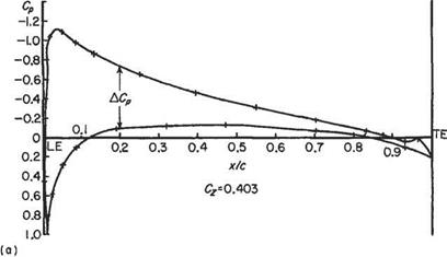
Ellipto-Zhukovsky section at the mid-section of a three-dimensional wing. Geometric incidence = 6" Reynolds number=4.8×10⁵
|
|
Fig. 1.20 Pressure distribution on an aerofoil surface |
w
d = pqT sine = pqT— = pwT per unit length
q
This rearwards component must be reckoned as a drag and is, in fact, the induced drag. Thus the induced drag arises essentially from the downwards velocity induced over the wing by the wing-tip vortices.

|
|
|
|
|
|
|
|
|
|
The further apart the wing-tip vortices the less will be their effectiveness in producing induced incidence and drag. It is therefore to be expected that these induced quantities will depend on the wing aspect ratio, (AR). Some results obtained in Chapter 5 below are:
where floo is the lift curve slope for the two-dimensional wing, and the trailing vortex drag coefficient Сд„ is given by
![]() Dv
Dv
‘{pV^S tv (AR) where 6 is a small positive number, constant for a given wing.
Lift-dependent drag
It has been seen that the induced drag coefficient is proportional to Cf, and may exist in an inviscid fluid. On a complete aircraft, interference at wing/fuselage, wing/ engine-nacelle, and other such junctions leads to modification of the boundary layers over the isolated wing, fuselage, etc. This interference, which is actually part of the profile drag, usually varies with the lift coefficient in such a manner that it may be treated as of the form (a + bCj). The part of this profile drag coefficient which is represented by the term (bCj) may be added to the induced drag. The sum so obtained is known as the lift-dependent drag coefficient. The lift-dependent drag is actually defined as ‘the difference between the drag at a given lift coefficient and the drag at some datum lift coefficient’.
If this datum lift coefficient is taken to be zero, the total drag coefficient of a complete aeroplane may be taken, to a good approximation in most cases, as
Cd = Cd0 + kC2L
where Cd0 is the drag coefficient at zero lift, and kC is the lift-dependent drag coefficient, denoted by Cdl-


