INFLUENCE OF SHAPE ON PLAIN WINGS
The wings of airplanes are not anything close to lifting lines. They are composed of panels with a certain chord – and thickness distribution, planform and shape. The influence of these parameters on lift is described as follows.
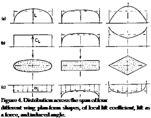
LIFT DISTRIBUTION. Figure 4 shows the lift distribution of three different planform shapes. It should be noted in particular:
(a) the elliptical wing has a constant and a uniform induced angle of attack.
(b) the rectangular wing has a somewhat more uniform distribution in newtons or pounds, while downwash is somewhat shifted from the center to the wing tips.
(c) the highly tapered (triangular) wing is loaded in the center, while the lift coefficient reaches comparatively high values near the tips.
(d) Wings with lateral edges show peaks at these edges, not predicted by theory, but nevertheless real.
 There are elaborate methods (8) available for computing lift distribution across the span of any given planform. We would like to mention here, only a simple procedure approximately indicating span wise distribution. According to (8,c, d) the load (in newtons or pounds) of a plane wing is distributed in such a manner as to form the mean between geometrical chord length and the elliptical shape. To find the distribution, it is thus sufficient to draw a half circle with the span as diameter, to plot the chord distribution in a scale so that the resultant plan- form area is equal to that of the half circle, and to take at a number of stations the mean between chord distribution and half circle.
![]()


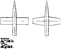
![]() TAPERED PLAN FORM. The simple lifting-line theory (equation 3) represents a minimum and thus optimum of the induced angle, obtained for elliptical load distribution. Theory expects that any deviation from this distribution results in a certain increase of the average or effective value of this angle-of-attack component. There are correction factors available, indicating the additional amount of induced angle for rectangular and tapered wing planforms. The theoretical correction can be presented in the form of the differential
TAPERED PLAN FORM. The simple lifting-line theory (equation 3) represents a minimum and thus optimum of the induced angle, obtained for elliptical load distribution. Theory expects that any deviation from this distribution results in a certain increase of the average or effective value of this angle-of-attack component. There are correction factors available, indicating the additional amount of induced angle for rectangular and tapered wing planforms. The theoretical correction can be presented in the form of the differential
(12)
where A/a = effective aspect radio and a — 0.9, for conventional airfoil sections. This function is an interpolation (by this author) of analysis (l, b)(10,b), applicable between A = 4 and 15. The factor K, as plotted in figure 5, is in theory smallest for taper ratios around 0.3. In fact, reference (10,b) predicts that the lift-curve slope of such wings is 99% of the theoretical as for elliptical load distribution. By comparison, the influence of fuselage and engine nacelles (see the chapter on ‘"airplane configurations”) can be much larger.
|
і igure 5. Factor k, theoretically needed in equation (5) to indicate the additional induced angle of attack, as a function of the taper ratio. |
(h’) influence of plan form on induced angle, theory:
Ц {;buen. ARC RM 723 (1922); “Elements Aerofoil 1 гкчігу, Cambridge 1926; quoted in Durand Vol II. th) і lueber. Character of Tapered Wings, Zts Flugt Motoriuftsch 1933 p 249 & 269, and Lufo 1938 p 218. c) Plan-form corrections for the induced drag, as premm-ч! in "Fluid-Dynamic Drag”, are different and nuncwhm smaller than for the induced angle.
U) Re issuer. Minimum Wing Drag, J A Sci 1940 p 114.
A – 4 dA -.14 И – 0.4
v 5(10)®
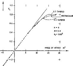
RECTANGULAR WINGS are expected by theory (figure 5) to be less efficient than elliptical or tapered wings. Tunnel tests on a set of three tapered wings are presented in figure 6. It takes a microscope to determine the differences in the lift-curve slope; and it may be said at this point that the selection of a plan form for the design of an airplane usually depends upon considerations other than the induced angle, such as structural or stalling. At any rate, the tabulation shows that. . . the moderately tapered wing has the lowest drag-due-to-lift derivative, and that the rectangular wing (with square lateral edges) has the smallest lift angle. There are many other results showing that rectangular wings with sharp lateral edges are very efficient in producing lift. Figure 7 demonstrates, for example, that the sharp-edged rectangular form is nearly as efficient as the elliptical wing of the same aspect ratio. Theory as in figure 5, is thus not confirmed (to be discussed later). When evaluating^ the induced angle of a rectangular wing, it must be considered that the effective area varies (reduces) together with the effective aspect ratio. If, for example, A reduces by A A = Ab/c = —0.1, then the area reduces by AS ==■ — Ab/b =. — (ДЬ/с)/А. As a consequence, the first two terms in equation (6) have to be increased. In equation (7) this is primarily done by the addition of (5/A) in the third term. In the case of figure 7, it is seen that when adding the fairings to the lateral edges, the induced characteristics remain unchanged. Comparing, however, a wing with rounded edges (e) on the basis of equal aspect ratio and of area including the added caps, it is found that A A = —0.12, and that the effective area is reduced by 2.5%.
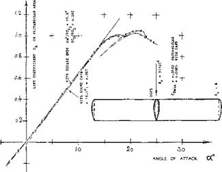
FOIL-SECTION THICKNESS evidently helps the flow to get around the lateral edges. Figure 8 presents a possibly extreme example. A 25% thick rectangular wind- tunnel airfoil was tested both with and without round fairings added to the lateral edges. Based on one and the same area (without the end caps) the wing without fairings is slightly more effective, as far as lift is concerned. Note that the due-to-lift drag derivative also favors the wing without the fairings, while the zero-lift drag coefficient of this wing is, of course, higher than that of the wing with rounded lateral edges. A simple assumption would be that the flow passes around the half-circular end caps to a degree as though they were not present. The fact that the original square-ended wing has a 3% higher lift-curve slope, might then be explained by a more outward location of the tip vortex, as in shape (1) in figure 10. Regarding drag, the two wings in figure 8 compare as follows:
Comiti= dC^/dCj^ — 0.062, square, edges
0. 0085, dCp /dC^ — 0.067, with end caps
For practical purposes, we thus find:
ДЬ/с = -(t/c) == ДА (13)
A rectangular wing with rounded lateral edges thus behaves, regarding its induced angle of attack and the effective area, roughly as though the end caps were not present (12,c). As in figure 8, the lift-curve slope (with C^ based on rectangular area) is usually slightly less than that of the wing without the tip fairings; see also (13, e).
|
Figure 8. Characteristics of a 25% thick rectangular airfoil; tested (13,g) with and without round fairings at the lateral edges. |
TAPERED WINGS. We may assume that the rounding effect be proportional to the chordwise dimension of the edge, indicated in tapered wings by the ratio c(tip)/c(root) = Л. Since the effect is also proportional to (t/c) at the wing tips, equation (13) holds for tapered wings when using for c and t the dimensions at the tips. We have evaluated the theoretical function as in figure 5 and equation (10) for A = 5.5. The result is plotted in figure 9, in the form of ДА = A-t — A, where Aj =. effective aspect ratio. A number of experimental points (some of which obtained in direct comparison to an elliptical plan form) clearly show the beneficial influence of lateral edges, particularly when they are sharp or square. Our final conclusion from experiments and analysis presented, is that the classical statement pronouncing the elliptical as the optimum plan form shape, is a “myth”, particularly when it comes to designing and fabricating a wing. Famous airplanes such as the Heinkel-70 and the “Spitfire” did have costly elliptical wings. Our graphs show, however, that a tapered wing can have at least the same aerodynamic effectiveness. Another argument against the elliptic plan form is offered in (10,d). The angle of the viscous or section drag is c*5 = CDs/Cl. Since in a real airplane, C|_ and (t/c) are highest at the roots of the wing, and c<sare larger there, than in the outboard portions of the panels. If minimum drag is expected for o^-F(0(5/2) = constant across the span, the optimum plan form is somewhere between elliptical and rectangular. Finally, it can be said that the “best” wing may not be optimum for an airplane, with a fuselage (see ”airplane configurations”) and with a horizontal tail surface exposed to the downwash coming from the center or the roots of the wing (see “longitudinal stability”).
“ROUND” PLANFORMS. In wing sections, a physical (so called Kutta-Joukowsky) assumption is necessary to fix the trailing edge as the point where the flow components coming from the two section sides, meet each other (in a rear “stagnation point”). A similar, never mentioned but equally necessary assumption, is that the tips of a finite-span wing coincide with the ends of the lifting line. As explained above, this is not true in the case of well-rounded lateral edges, as in figure 8 for example. In a similar manner, wing “tips” with well – rounded plan form shape result in an effective aspect ratio which is smaller than the geometrical one. The path of the trailing vortex is shown in figure 10, for three different tip shapes of a basically rectangular wing, with A =- constant = 3. According to equation (1) the roll-up distance (say behind the quarter-chord line) is in the order of x/c = 10, for Cj_ = 0.6. The path of the tip vortex was traced to only one chord downstream from the trailing edge in the investigation discussed. The location of the vortex at this distance may permit, however, to estimate the reduction of the “vortex span” of the shapes tested, in comparison to that of the basic rectangular wing. Values of ДА,, evaluated from experimental results of doC’dCj_ of various shapes, were found to be proportional to the lateral displacement (Ду/с) as defined in figure 10. Assuming
|
figure 9. Differential ДА of the effective aspect ratios of tapered wings having a geometrical ratio A — 5 to 6, as a function of their taper ratio. |
ill V n lorin and induced angle, experimental:
a) !),4’r^h. Rectangular/Elliptical, Ybk D Lufo 1940.
1)1 І– gehmsse AVA Gottingen, Vol I (1921) p 63.
0 {-v/tLerr. Control Surfaces, Ybk D Lufo 1940, 542. cl ) bib. t;-tein. H’Tail Collection, NACA T’Rpt 688.
G Circular Wings, see Yearbk D Lufo 1939 p 1-152, andZimmerman in NACA Tech Note 539 (1935).
i),ans(‘n – 5 Elliptical, Ybk D Lufo 1942 p 1-160.
g) Purser. Various Wing Shapes, NACA TN 2445 (1951). j Knight, Various at R — 2(10* NACA TR 317 (1929). "
|
Figure 10. Location and path of the trailing vortex originating along the lateral edge of a basically rectangular wing, having an aspect ratio A — 3, as found (13,f) for six different wing-tip shapes. |
that the volume of air affected (deflected) by the wing be proportional to the square of the vortex span b*, the average induced angle may be expected to correspond to
A; = A+ ДА = (b-t – Abf/S = А + 2(ДЬ/с) (14)
For shapes (1) and (3) substitution of 2( Ду/с) for (ДЬ/с) leads by way of equations (4) and (6), correctly to the lift angles as tested. Doing this, it is not assumed that the effective area would be reduced.
|
|
|
BXF. dcf/dCj. do£/dCL Дъ/о 11.0 19.9 7.0 0 13,Ъ 18.7 7.0 0 11.0 20.8 7.В -.10 13,b 19.6 7.5 -.10 11.0 21.5 8.5 -.18 13.0 19.0 8.2 -.16 |
t/o ■ 11.7 to 13*5 (11,c) tested with flap and gap (13»e) tested in closed tunnel,
while all others in open tunnels
Figure 11. Reduction of the effective aspect ratio of “round” wings as against the sharp-edged rectangular shape having the same aspect ratio A — 3.
R0 – 2(10У
 Figure 12. Comparison of a basically rectangular wing with A =■ 6 =r constant, for three different planform shapes of the ends or tips (ll, h).
REAR CORNER. Some more “round” planform shapes are shown in figure 11. Here and in figure 12, it is seen that cutting away from the rear corners of the plan form is particularly harmful in reducing lift-curve slope and effective aspect ratio. For conventional thickness ratios (between 11 and 13% as tested), Ab/c reaches values, as against the sharp-edged rectangular wing having the same aspect ratio, roughly between —0.2 and —0.3, for round or cut-away shapes. This reduction is larger than that for rounded lateral edges (preserving rectangular planform) where Ab/c is between —0.10 and —0.14, for the thickness ratios, investigated. Such values are to be used to modify the sectional as well as the induced angle required to produce a certain lift coefficient. Accounting for the loss of useful span of the round or raked, and rounded two tip shapes in figure 12, only by way of an effective aspect ratio, values of A A = —0.4 and —0.5 are found, in comparison to rectangular and square-edged Wing.
“U” SHAPE. Wing ‘5’ in figure 10 is very effective, despite the fact that the vortex span is somewhat small by comparison (19). It was found, however, that the trailing vortex is located at a level some 6% of the wing chord higher than in the case of other wing ends tested. The bent-up tips seem to serve as a low type of end plates (see later). Taking the 6% as measured (which are equal to 0.5 (t/c) of the foil section used) it can be assumed that the wing tips impose upon the vortex sheet a “U” shape with an equivalent end-plate height h/b =
0. 06/A =2%. According to equation (25) the corresponding increment of the effective aspect ratio is ДА = 2(0.02) =■ 0.04. This much helps, but it
is not yet enough to explain the performance of shape ‘5’. It is suggested that the clean flow around the wing tip, as shown in Chapter VII of “Fluid-Dynamic Drag”, may be responsible, (a) for the complete preservation of the effective area, (b) for minimum parasitic drag due to lift, and (c) possibly for a more favorable rollup process in the wing’s vortex wake. These arguments are supported by trying the opposite, id est adding drag.
TIP DRAG. As reported in (15) a pair of spheres (as in ball bearings) was attached to the lateral edges of the horizontal-tail-surface model as in figure 13. When writing the well-known equation for the induced angle in the form of
dcX;/dCLb — 1/ir = 180/1^=18.3° (15)
where Cuj—L/qb, an angle is found which is independent of the aspect ratio A = b/c. In the experiment, it was found that
A(X /ДСц — 19.0° for the plain wing tips,
hoc /ACl = 19.8°, with the spheres attached.
The effective aspect ratio is thus A[ = ‘(19/19.8) A =
0. 96 A. The reduction caused by the spherical obstacles (15.b) is A A =- —0.04 A, which is ДА = —0.14, for A =. 3.7. In other words, a strip of Ab/c =■ AAAI =■ 0.035, is effectively cut-off from each lateral edge of the rectangular wing, when disturbing the flow along and around the edges. When eliminating a similar disturbance by means of the “clean” tip shape ‘5’, the superior performance of this type of edge can be understood (19).
|
Figure 13. Experiment (15) demonstrating the influence of a pair of obstructions (spheres) upon the lift of a horizontal tail surface. |
(12) Small-aspect-ratio considerations:
a) Jones, NACA TN 817 and T’Rpt 835 (1946); also in “High-Speed Aerodynamics” Vol VI of Princeton Series.
b) Bartlett, Lateral Edges, J Aeron Sci 1955 p 517.
c) This result agrees with the concept in (a) and (bl whereby any “retracting” parts of lateral edges, behind maximum span, do not contribute to lift.
(13) Influence of tip shape on wing characteristics:
a) Hoerner, Fieseler Water-Tunnel Rpt 16 (1939).
b ) Kesselkaul, Tests of Wings with Various Lateral – Edge Shapes, Inst Aircraft Des Braunschweig, 1941.
c) Zimmerman, Small A’Ratios, NACA TN 539 (1935).
d) Hoerner, Aerodynamic Shape of Wing Tips,
USAF AMC Tech Rpt 5752 (Wright Field 1949).
e) Goett, Rounded Edges, NACA T’Rpt 647 (1939).
f) Hoerner, Tip Vortex Measurements Behind 6 Wing Shapes, ZWB UM7815 (Messerschmitt Rpt TB-92/1943).
g) Bullivant, 0025 and 0035, NACA T’Rpt 708 (1941).
h) Experiments similar to (b) and (f) by Valensi in Pub! Sci Tech Ministere de Г Air, 1938 No. 128.
(14) Characteristics of wings with dihedral shape: a) Purser-Campbell, Experimental Verification of Vee-Tail Theory and Analysis, NACA Rpt 823 (1945).
h) Datwyler, Mitteilung Aerody Inst TH Zurich, 1934. c) Schade, “V” Tail Forces, NACA TN 1369 (1947).
15) Engelhardt, Influence of Fuselage Upon Horizontal Tail, Rpt Aerody Lab TH Munchen (1943).
Figure 14. Effective aspect ratio of wings with end
plates (18) as a function of their height ratio.


