Numerical Solution to Inflow Equation
Because a can never be zero in any practical case, Eq. 2.126 is usually solved numerically. While analytic solutions of the inflow equation for а ф 0 are possible, proper selection of the correct root from a set of multiple complex roots make the approach academic and of little practical engineering use. There are two common numerical approaches:
1. A simple fixed-point iteration or 2. A Newton-Raphson iteration. The algorithm for the fixed-point iteration is extremely simple. It consists of a loop to iteratively compute new estimates of к until a termination criterion has been met. Equation 2.126 can be written as the iteration equation
Ct
kn+i = tit ana-1—— . ——– (2.132)
2УД+ЇЇ
where n is the iteration number. The starting value for Ao is usually the hover value (i. e., k0 = kh = у/Ст/2 )• The error estimator is
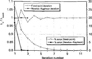
Normally, convergence is said to occur if є < 0.0005 or 0.05%. One normally finds that between 10 and 15 iterations are required with the fixed-point iteration approach (Fig. 2.25). However, under some conditions, especially at lower advance ratios, a larger number of iterations may be necessary.
One can also use a Newton-Raphson procedure to solve for k. The advantage here is that for the price of computing a simple first derivative the convergence is much more rapid. In this case, the iteration scheme is
![]() ‘ m’
‘ m’
-/w I’
where n is the iteration number. Equation 2.126 may be rearranged in the form f{k) = 0 giving
Differentiating this expression to find /'(A) gives
/'(X) = l + ^(^ + A.2)"3/2X. (2.136)
Although the Newton-Raphson method can be sensitive to the starting value (initial conditions), in most cases the hover value Ao = A* works well, with only 3-4 iterations
|
Figure 2.25 The solution of the inflow equation is obtained iteratively, with rapid convergence. |
being required to reach the tolerance compared to up to 10 or more iterations using fixed – point iteration, as shown in Fig. 2.25. However, the computing costs with either method are essentially trivial on a computer. See also Questions 2.17 and 2.18.
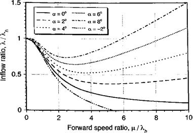
Results for the inflow ratio A,/kh as computed using the iterative scheme are plotted in Fig. 2.26 for several different values of a (both positive and negative) and over a range of values of fx/Xh typical of a helicopter. Notice that the induced part of the total inflow decreases with increasing advance ratio and the total inflow becomes dominated by the jx tan a term at higher advance ratios. Notice also that negative disk angles ultimately produce a negative inflow (upflow) through the disk, which means that the rotor is approaching a zero power required state or the autorotational condition (see Section 2.14.6).
|
Figure 2.26 Inflow ratio X/Xh as a function of forward speed ratio /хДА for several rotor disk angles of attack. |
2.14.2 General Form of the Inflow Equation
The inflow equation given by Eq. 2.126 needs to be written in a more general form for climbing or descending flight. In this case the inflow ratio can be rewritten as
Cj
к = xx tan a H——- ————- + jxy. (2.137)
2 у l^x T
where = VooCosa/SIR and ц, у = Vasina/SIR can be recognized as the advance ratios defined parallel and perpendicular to the rotor disk, respectively. It will be apparent that this latter equation can be written simply as
Cf
k = x tanaH—– -===== T kc cos oc. (2.138)
2v^+l2


