Other Types of Aerofoils
After the six-series sections, aerofoil design became more specialized with aerofoils designed for their particular application. In the mid-1960s, Whitcomb’s “supercritical” aerofoil allowed flight with high critical Mach numbers (operating with compressibility effects, producing in wave drag) in the transonic region. The NACA seven and eight series were designed to improve some aerodynamic characteristics. In addition to the NACA aerofoil series, there are many other types of aerofoils in use.
To remain competitive, the major industrial companies generate their own aerofoils. One example is the peaky-section aerofoils that were popular during the 1960s and 1970s for the high-subsonic flight regime. Aerofoil designers generate their own purpose-built aerofoils with good transonic performance, good maximum lift capability, thick sections, low drag, and so on – some are in the public domain but most are held commercial in confidence for strategic reasons of the organizations. Subsequently, more transonic supercritical aerofoils were developed, by both research organizations and academic institutions. One such baseline design in the United Kingdom is the RAE 2822 aerofoil section, whereas the CAST 7 evolved in Germany. It is suggested that readers examine various aerofoil designs.
The NASA General Aviation Wing (GAW) series evolved later for low-speed applications and use by general aviation. Although the series showed better lift-to – drag characteristics, their performance with flaps deployment, tolerance to production variation, and other issues are still in question. As a result, the GAW aerofoil has yet to compete with some of the older NACA aerofoil designs. However, a modified GAW aerofoil has appeared with improved characteristics. Appendix D provides an example of the GAW series aerofoil.
Often, a wing design has several aerofoil sections varying along the wing span (Figure 3.12). Appendix D provides six types of aerofoil [4] for use in this book. Readers should note that the 2D aerofoil wind-tunnel test is conducted in restricted conditions and will need corrections for use in real aircraft (see Section 3.12).
|
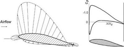
(a) Pressure field distribution (b) Cp distribution over aerofoil Figure 3.13. Pressure field representations around aerofoil |


