Problems
3.9.1
Calculate the horizontal perturbation velocity u(x, 0) due to an ellipse at zero incidence. The thickness distribution of the ellipse is given by e(x) = 2^/| (1 – |). Hint: use Glauert change of variable. Why was this thickness distribution not included in the family of profiles with minimum pressure gradient?
3.9.2
Calculate the horizontal perturbation velocity u(x, 0) due to a biconvex airfoil at zero incidence. The thickness distribution of the biconvex profile is given by e(x) = 4e| (1 – D. Hint: use Glauert change of variable. Sketch the pressure coefficient – Cp.
3.9.3
Calculate the horizontal perturbation velocity u (x, 0) due to a double wedge airfoil at zero incidence. The thickness distribution of the double wedge profile is given by e(x) = §Ox, 0 < x < § and e(x) = 26(c – x), § < x < c. Hint: no change of variable is necessary. Sketch the pressure coefficient – Cp.
3.9.4
Consider a thin flat plate with a break in slope at x = §. The equation of each piece is given by d(x) = Ox, 0 < x < § and d(x) = 6(c – x), § < x < c. Calculate the horizontal perturbation velocity u (x, 0) and C± . Hint: Use the integral formulae given for the Fourier coefficients. Find the angle of adaptation aadapt. Give the values for Ci(a) and Cm, o(a). Sketch – C± at aadapt.
3.9.5
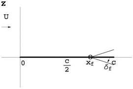
A double wedge airfoil at zero incidence (a = 0) is moving with velocity U in a uniform atmosphere. The geometry of the airfoil is sketched in Fig.3.30. The halfangle is 0 << 1rd. The equation of the upper surface is z+(x) = Ox, 0 < x < c/§, z+(x) = O(c – x), c/§ < x < c. Find the perturbation velocity (u, w) on the upper surface, given that u(x, 0) = U z x(-d^. Give the Cp distribution at a = 0 and make a sketch of it. Will there be a lift force? A drag force? The incidence is changed to a > 0. Give the new Cp distribution and make a sketch of it. What will the lift coefficient be? The drag coefficient?
3.9.6
A thin airfoil problem is characterized by small, dimensionless parameters of order O ^ 1. Give the definition of these small parameters. Give the definition of the Center of Pressure. In inviscid, incompressible flow, give the formulae for the lift coefficient Ci, drag coefficient Cd and moment coefficient Cm, o of a thin parabolic
Fig. 3.30 Problem 3.9.5: Double wedge airfoil

 Fig. 3.31 Problem 3.9.7: Flat plate with flap
plate in terms of the small, dimensionless parameters. If thickness is added to the plate, how do these coefficients vary?
If this thin profile is allowed to rotate freely about an axis placed at the leading edge, find the equilibrium incidence. Hint: the moment of the aerodynamic forces is zero (neglect weight). Is the equilibrium statically stable?
3.9.7
A thin flat plate has a hinge located at (xf, 0), 0 < Xf < c, about which the end of the plate can rotate by an angle Sf (positive down) and that plays the role of a flap. The equation of the thin plate is given by:
![]() 0, 0 < x < Xf
0, 0 < x < Xf
Sf (xf — x), xf < x < c
Calculate the slope d’ (x) of the plate (check your algebra as other results depend on this). See Fig. 3.31. Let tf be the value of the parameter t corresponding to the flap hinge in the classical parametric representation of the thin plate as x f = x(tf) = 2(1 — cos tf), 0 < tf < n. Using the formula derived in class A0 = а — П jn d'[x(t)]dt, calculate A0. Check your result for tf = n (xf = c). Conclude. Check your result for tf = 0 (xf = 0). Conclude.
What is the angle of adaptation aadapt(tf, Sf)? Check your result for tf = n (xf = c). Conclude. Check your result for tf = 0 (xf = 0). Conclude. Calculate the incidence of adaptation for xf = 3c/4 and Sf = 10°.
Sketch the plate and, qualitatively, the flow at the calculated incidence of adaptation, in particular the streamlines near the leading edge and the trailing edge.
Calculate A1 in terms of the average camber d, tf and Sf. Check your result for tf = n (xf = c). Conclude. Give the value of the aerodynamic coefficients C; and Cd in terms of a, tf and S f. If thickness is added to the thin plate, how will these coefficients be affected?
References
1. Glauert, H.: The Elements of Aerofoil and Airscrew Theory, 2nd edn. Cambridge University Press, Cambridge (1948)
2. Chattot, J.-J.: Optimization in applied aerodynamics. Comput. Fluid Dyn. J. 9(3), 306-311 (2000)
3. Drela, M.: MSES—Multi-element airfoil design/analysis software. http://raphael. mit. edu/ research. html (1994)
4. Chattot, J.-J.: Computational Aerodynamics and Fluid Dynamics: An Introduction. Scientific Computation. Springer, Berlin (2004)


